Page is loading ...

Owner’s Manual AQ-RO-3
Aquasana OptimH2O
™
Drinking Water System
Reverse Osmosis plus Claryum
®
Filtration Technology
Welcome to the Aquasana experience. You are about to enjoy clean, clear water and the peace
of mind that comes from knowing award winning filter technology is working for you.
System tested and certified by NSF
International against NSF/ANSI Standard
42, 53 & 401 and conforms to NSF protocol
P473 for reduction of claims specified on
the Performance Data Sheet and at nsf.org.
The AQ-RO-3 system has been tested and
certified by NSF International against NSF/ANSI
Standard 58 for the reduction claims specified
on the Performance Data Sheet as verified and
substantiated by test data and at nsf.org.

WARNING: Using a qualified installer is recommended.
Proper installation is the responsibility of the installer.
Product failure due to improper installation is not covered under the warranty.
NOTE: Keep these instructions for future reference
PLAN FOR INSTALLATION
Prior to installation, we recommend you read the entire manual to familiarize yourself with the
system, and help you determine the best location for installation. Please check and comply with
all local plumbing codes.
PREPARE SITE FOR INSTALLATION
NOTE: If you have metal drain pipes, consult a plumber for installation of drain connection.
1. Prior to installation, close the cold water shut-o valve.
2. Temporarily place system manifold, remineralizer, and
tank into the under sink cabinet or desired location
to ensure adequate space and proper positioning.
3. ⁄" white tubing will be used to connect manifold to tank, and from faucet stem to
remineralizer. Measure out ⁄" white tubing from the top of the tank to the outlet side of the
system manifold and mark ⁄" tubing. Then measure remaining length of ⁄" tubing from the
remineralizer to the desired location of the faucet hole to ensure there will be enough ⁄"
tubing available for both connections. Wait to cut tubing and follow instructions below.
4. Remove system, remineralizer, and tank from under your sink to begin installation.
INSTALLATION OVERVIEW
Step 1 - Install Brass Tee Fitting
Step 2 - Install RO System Manifold
Step 3 - Install Water Storage Tank
Step 4 - Install RO Faucet
Step 5 - Install RO Drain Connector
Step 6 - Connect Tubing
Step 7 - Stage 1–3 Filter Installation
Step 8 - Sanitize, Pressure Test, Purge System
REQUIRED TOOLS & MATERIALS
• Basic plumbing knowledge
• Tape Measure
• Utility Knife
• Screwdriver (Phillips)
• ⁄" & ⁄" Drill Bits/Drill
• Adjustable Wrench
• Bleach
• Safety Glasses
• Pencil
• Masking Tape
• Pan or Bucket
WHAT’S INCLUDED
A System Manifold
B Carbon Filter Sump
C Membrane Filter Sump
D Claryum Filter Sump
E Remineralizer
F Faucet
G Gasket, Nut, Washer, Spacer,
Quick Connector (for faucet)
H Water Storage Tank
I Eye Dropper
J Tank Connector
K Plumber’s Tape
L Drain Connector
M Nuts & Bolts
N Foam Seal
O Flow Restrictor &
90° Elbow
P Tubing ¼" White
Q Tubing ⁄" White
R Tubing ⁄" Red
S Screws + Bracket
T Brass Tee
U Carbon Filter Cartridge
V Claryum Filter Cartridge
HOT
OptimH2O™
Stage
RO Membrane
AQ-RO3-RO
OptimH2O™
OptimH2O™
Remineralizer
AQ-RO3-RM
COLD
A
B DC E
F
G
H
L
T
R
Q
P
J
A
B
F
G
H
I
J
K
L
M
N
O
P
Q
R
S
T
U
V
C
D
E
OptimH2O™

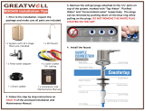
INSTALL BRASS TEE FITTING
1 Turn o the cold water supply to the sink.
2 Turn on the kitchen faucet to release pressure and allow water to drain from the line.
3 Disconnect the cold water line from the ½" threaded stem on the bottom of the kitchen
faucet. Attach threaded ends of supplied brass tee to the cold water supply line and shut-o
valve; tighten using an adjustable wrench.
4 Attach ¼" white tube to the brass tee:
A. Slide the compression nut onto the white tubing.
B. Slide the plastic sleeve onto the white tube.
C. Place brass insert into the opening of white tube.
D. Push the tip of the white tubing into the opening of the brass tee.
E. Slide the compression nut onto the threads of the brass tee.
F. While holding the white tube in place, tighten the compression nut to compress the plastic
sleeve and create a seal. NOTE: Use a wrench to ensure complete seal. Avoid over tightening.
5 Do not connect the other end at this time.
1 On the nipple on top of the tank, apply plumber’s
tape 4 or 5 times clockwise around in the same
direction as the threads.
2 Hand tighten the tank connector onto the tank
nipple until secure. NOTE: Do not cross thread or
over tighten.
3 Using mount stand, place tank near the system
manifold. Measure ⁄" white tubing to the outlet
side of the system manifold and ensure you
have enough tubing to connect tank and system
manifold as well as enough left to attach faucet
stem and remineralizer. Cut ⁄" white tubing.
Stage
RO Membrane
AQ-RO3-RO
OptimH2O™
OptimH2O™
A B C D E F
OptimH2O™
OptimH2O™
OptimH2O™
OptimH2O™
OptimH2O™
OptimH2O™
OptimH2O™
A B C
2
1
INSTALL SYSTEM MANIFOLD
1 Select an easily accessible area under the sink to mount system
manifold and remineralizer holder. You want to allow at least a 4
to 6 inch clearance below the filters to the floor to allow ample
space for filter changes. To help gauge the right location for your
system manifold, insert first and third stage filter sumps into
manifold. Insert sumps by aligning top connection points and
push up and to the right until sumps are locked in.
2 Mark wall placement for mounting screws using
built-in bracket on back of manifold. Make sure holes
are as level as possible. Mark screw placement of
the remineralizer holder 1 or 2 inches from the third
stage sump to the right of the manifold.
3 Drill two pilot holes for mounting brackets using ⁄"
drill bit for the system manifold. NOTE: Use caution
not to drill into anything beyond the cabinet wall.
4 Insert mounting screws into the wall leaving approximately ⁄" of each screw exposed.
5 Remove first and third filter sumps from manifold by turning each sump to the left and
pulling down before hanging manifold on wall. Mount manifold on wall and screw in. Be
careful not to over tighten.
6 Screw in remineralizer holder onto wall.
4 Install the ⁄" white tubing to the tank:
A. Push the tubing through the nut, collar and sleeve into the connector.
B. Unscrew the compression nut from the tank connector to ensure that the tubing is
connected all the way through the collar and sleeve.
C. Slide the nut to the threads and tighten with a wrench. Avoid over tightening.
INSTALL WATER STORAGE TANK

INSTALL RO FAUCET
You will need a sink top hole 1" in diameter. If drilling a new hole, ensure faucet body will
mount flat against surface and that there is sucient tubing between faucet body and system
manifold. NOTE: Drilling holes into solid surfaces or surfaces made of stone should only be
performed by a qualified and certified installer.
1 Place the black rubber gasket into the groove of the faucet base and feed the tubing and
faucet threads through the countertop hole.
2 Underneath counter, slide on the slotted washer, spacer and nut. Tighten with wrench.
3 Tighten the white quick connector onto the base of the faucet threads.
4 Attach ⁄" white tubing by inserting into quick connector approximately ⁄" until it stops.
Gently tug on the tubing to ensure it is firmly seated in fitting.
NOTE: Do not connect ⁄" white tubing from tank to faucet.
INSTALL RO DRAIN CONNECTOR
WARNING
CAUTION
Be sure that all electrical appliances and
outlets are turned o at the circuit breaker
before working in the cabinet area.
Please wear safety
glasses to protect
eyes when drilling.
1 Identify drain outlet location. Do NOT install the drain connector onto the same drain pipe
as the garbage disposal whenever possible.
2 Remove protective cover from back of foam seal.
3 Knock center hole out, align holes, and attach to front plate of drain connector.
4 Allowing room for drilling, position the drain connector on sink drain pipe above drain trap.
5 Securely tighten nuts and screws.
6 Using the drain connector port as a drill guide, drill a ⁄" hole into the drain pipe. Be sure
not to penetrate opposite side of pipe, or to damage side of the drain port fitting.
COLDHOT
gasket
washer
quick connector
spacer
nut
drain pipe
bracket
new hole
Pro Tip
If there is leakage from the
drain bracket, loosen the bolts
and slide the bracket up so the
drilled hole is at the bottom of
the drain connector port.

WARNING:
Faucet will leak
if restrictor is
not installed
CONNECT TUBING
I: Brass Tee to Manifold “INLET” (¼" white tubing)
1 Take the white tubing leading from the brass tee and insert it into the manifold port
labeled “INLET”. Remember to push it all the way in until it stops.
II: Manifold to Remineralizer (⁄" red tubing included in packaging)
1 Insert one end into the manifold port labeled “FAUCET”.
2 Insert the other end into the remineralizer port labeled “INLET”.
III: Remineralizer to Faucet (⁄" white tubing already attached to faucet)
1 Insert the ⁄" white tubing (that was installed in step 4) from the faucet into the
remineralizer port labeled “OUTLET”.
IV: Manifold to Tank (⁄" white tubing already attached to tank)
1 Take the white tubing leading from the storage tank and
insert it into the manifold port labeled “TANK”. Remember
to push it all the way in until it stops.
V: Air Gap to RO Membrane (¼" red tubing from faucet)
1 Insert restrictor into the end of the red tubing.
2 Attach ¼" red tubing to the ° elbow until it stops.
3 Attach ¼" ° elbow to the membrane drain port.
VI: Faucet to Drain Connector (⁄" red tubing from faucet)
1 Take the ⁄" red tubing from faucet and insert it all
the way into the drain connector.
COLDHOT
Hose Connections:
¼" White Brass Tee to Manifold
3⁄8" Red Manifold to Remineralizer
3⁄8" White Remineralizer to Faucet
I
I
II
III
3⁄8" White Manifold to Tank
¼" Red Membrane to Faucet
3⁄8" Red Faucet to Drain Connector
IV
V
VI
V
II
IV
III
VI
OptimH2O™
Stage
RO Membrane
AQ-RO3-RO
OptimH2O™
OptimH2O™
Remineralizer
AQ-RO3-RM
123
0.95"
Tube Marking Guide:
(actual size)
Tubing Dont’s
DO NOT cut tubing too short. Always double check
measurements before cutting.
DO NOT bend or crimp or kink tubing.
DO NOT discard excess tubing.
Tubing Do’s
Insert tubing ALL THE WAY IN to prevent
leaking. In most cases, up to nearly a full inch.
Wet end of tubing to more easily insert into all
inlets and outlets.
Cut excess tubing in order to prevent crimping,
kinks, loops or folds.

SANITIZE, TEST & PURGE
Sanitize
Note: Sanitization is recommended immediately after RO Filter System installation and any inner-part
servicing. The person sanitizing should have clean hands during this process.
1 Shut o water supply to RO system.
2 Open faucet. If tank is not empty, allow to
drain until empty.
3 With included eyedropper and household
bleach (5.25%), disconnect white tubing
from the manifold outlet labeled “TANK”.
Note: Bleach needs to be handled
according to manufacturer’s instructions.
4 Add 3ml bleach into open end of tank white
tubing.
5 Reconnect the tank from the tube into the
manifold outlet labeled “TANK”. Be sure to
push tubing in all the way.
6 Sanitation will be completed during the following pressure test and purge. Important:
Bleach must be completely removed from system before drinking water. See Purge
instructions below.
Pressure Test
Important: Complete sanitization prior to pressure test.
1 Open cold water supply valve to RO Filter System.
2 To purge air from the plumbing system, open kitchen faucet. Close faucet when water runs
smooth.
3 Confirm RO faucet is closed.
4 Within approximately 2 hours, pressure will start to build in the RO Filter System. Carefully
inspect all connections and fittings while this pressure buildup occurs.
5 Check for leaks. If leaks are found, fix by ensuring all tubing is cut squarely and fully inserted.
Also confirm there are no scratches, dents or notches at tubing end. If there are, squarely cut
1" o and re-insert.
Note: When RO Filter System is first pressurized, water may project
from faucet air gap hole until air is passed from RO Filter System.
Purge
1 Open RO faucet and let water flow through system for 24 hours.
Note: Flow rate will be slow during this time.
2 Close RO faucet after purge is complete.
Note: Your RO Filter System is ready for use when purge is complete, however, you will not have filtered
water immediately. It takes 1-3 hours to completely fill the tank. The flow rate will be less than your
kitchen faucet. Water will run to the drain while the RO Filter System is filtering water – even when not in
use. This is normal. Water going to drain will stop automatically when tank is at capacity.
STEP FILTER INSTALLATION
Before you begin: make sure the cold water valve is shut o and there is no pressure in the system. Carbon
(red) and Claryum (yellow) filter cartridges will come pre-installed in their cartridge sumps.
1 Attach red carbon sump to the 1st stage position on the inlet side of the system manifold.
Make sure all connection points are aligned and push the top of the sump up and into the
system manifold. Turn it towards the right until it locks in.
2 Repeat step 1 for the 2nd Stage RO membrane that goes in the center, and for the yellow
Claryum cartridge in the 3rd stage position on the outlet side of the system manifold.
Be sure to turn 2nd stage RO membrane all the way to the right, until drain port on cartridge is
facing the rear of the system.
OptimH2O™
Stage
RO Membrane
AQ-RO3-RO
OptimH2O™
OptimH2O™
Remineralizer
AQ-RO3-RM
1
1
2
3
3
2
1
3
3
2
1
A
B
C
D
2
1
2
1
2
1

3-STAGE RO SYSTEM – MODEL AQ-RO-3
U.S. Metric
Membrane Production
1
35 gpd 132 lpd
Membrane TDS Reduction
1
95% minimum 95% minimum
System Production
2
13.32 gpd 50.4 lpd
TDS Reduction
2
96.3%+ average 96.3%+ average
Maximum TDS 1000 ppm 1000 ppm
Maximum water hardness @ 6.9pH 10 gpg 2.64 gpL
Maximum Chlorine in water 3.0 ppm 3.0 ppm
Supply water pH limits 4-10 4-10
Drain (reject water) Flow 3-5 x product flow 3-5 x product flow
Empty Storage Tank Precharge 5-7 psi air 35-48 kPa air
Storage Tank Capacity
2
3.2 gallons 12.11 liters
Supply water pressure limits 40-100 psi 275-689 kPa
Supply water temperature limit 40-100 F 5-37 C
Eciency
3
17.91% 17.91%
Recovery
4
29.43% 29.43%
Capacity at various water pressure levels (with 5 psi precharge) U.S. Gallons
Total Volume 20 psi 30 psi 40 psi 50 psi 60 psi 70 psi
3.2 1.4 1.8 2.0 2.2 2.4 2.5
Specications – Qualied System Performance
Because the performance of a Reverse Osmosis Membrane is highly dependent upon pressure,
temperature and TDS, the following should be used for comparison purposes only.
1 Industry standards measure RO Membranes performance with no back pressure on the
product water, at 60 psig (414kPa) and 77°F (25°C). Further conditions on the above are 250
ppm TDS and a 30.6% recovery rate. Production rate and TDS reduction figures are for a new
Membrane that has been rinsed for 24 hours. The production rate of a new Membrane can
decrease by 10% per year or more, depending upon the scaling and fouling tendencies of the
Feed Water.
2 Measured at 50 psi, 77°±2°F, and 717 mg/l TDS per NSF/ANSI Standard 58.
3 Eciency rating means the percentage of the influent water to the system that is available
to the user as reverse osmosis treated water. Under operating conditions that approximate
typical daily usage.
4 Recovery rating means the percentage of the influent water to the membrane portion of
the system that is available to the user as reverse osmosis treated water when the system is
operated without a storage tank or when the storage tank is bypassed.
Do not use with water that is microbiologically unsafe or of unknown water quality
without adequate disinfection before or after the system. Systems certified for cyst
reduction may be used on disinfected waters that may contain filterable cysts.
Filter is only to be used with cold water. Systems certified for cyst reduction may be
used on disinfected water that may contain filterable cysts.
Non-potable Water Sources:
Do not attempt to use this product to make safe drinking water from non-potable water
sources. Do not use the system on microbiologically unsafe water, or water of unknown quality
without adequate disinfection before or after the system. This system is certified for cyst
reduction and may be used on disinfected water that may contain filterable cysts.
Installations in The Commonwealth of Massachusetts:
The Commonwealth of Massachusetts requires installation be performed by a licensed plumber
and do not permit the use of saddle valves. Plumbing code 248—CMR of the Commonwealth of
Massachusetts must be followed in these cases.

Carbon Pre-Filter & Claryum
®
Post-Filter - Change every 6 months*
The carbon and Claryum filter cartridges are replaceable activated carbon cartridges located
in stages 1 and 3. It is recommended replacing these cartridges at least every 6 months. You
may need to replace more often with high water usage or high sediment level. Replacing these
cartridges timely will protect the RO membrane from high levels of chlorine and/or sediment.
As these filters build up with sediment, you may notice slower water output.
RO Membrane Cartridge - Change every 12 months
The RO membrane is located in stage 2. This membrane reduces the dissolved solids and
organic matter. Most municipally treated water has a 7.0-7.5 pH, in this case you would need to
replace your RO membrane every 12 months. Membrane life depends on pH and supply water
hardness. Higher pH shortens membrane life by causing pin-hole leaks, and would shorten
membrane life. When output and water quality and production rate decrease, it is time to
replace the filter sump.
Remineralizer - Change every 12 months*
Important: For the first 36 hours after the initial installation, make sure to periodically inspect
for leaks while the system is running and while it is turned o. If a leak occurs, shut o the
water supply, open up the filter faucet to release pressure from the system & contact Aquasana
Technical Support 866.662.6885.
If you are adding the remineralizer to a system that has already been installed, shut o the filter
faucet, turn on the water supply and allow the RO tank to fill up completely. Once the tank is
completely filled, flush & saturate the remineralizer cartridge by opening up the filter faucet
and allowing the purified water to run through the remineralizer for 3 minutes. The water may
come out cloudy during the initial flush.
*Filter life depends on water usage and water supply quality.
Faucet is not part of NSF Certification
Nitrate/Nitrite Test Kit:
This system is acceptable for treatment of influent concentration of no more than 27mg/L
nitrate and 3mg/L nitrite in combination measured as N.* This system is supplied with a nitrate/
nitrite test kit. Product water should be monitored periodically according to the instructions
provided with the test kit.
Drain Flow Restrictor
The restrictor is vital for proper operation of the RO membrane cartridge as it keeps water
flowing through the membrane at the proper rate ensuring the water produced is the best
quality. It is recommended the restrictor assembly be periodically inspected to be sure it is
clean and unrestricted. If service is required on the drain flow assembly, disassemble and
reassemble as outlined in Step Six.
Flow rate and output are determined by 3 factors:
1 Incoming water temperature
2 Total dissolved solids (TDS) present in supply water
3 Incoming water pressure
Lower temperatures are directly proportional to slower flow rate. All membranes are tested at
77°F. Incoming water temperature should not exceed 100°F. The RO Filter System should also
not be installed in a location susceptible to freezing. The more TDS in the supply water, greater
filter time is required. Incoming TDS should not exceed 1000 ppm. Higher water pressure
enables a higher flow rate. Pressure must be above 40 psi for proper system operation. You may
consider installing a permeate pump or booster pump if your pressure is below 40 psi.

RO_PDS_20161118
Testing performed under NSF/ANSI Standards 42, 53, 58 and 401 and in accordance with the California State Water Resources Control
Board.This system has been tested according to NSF/ANSI 42, 53, 58, 401 & P473 for reduction of the substances listed below. The
concentration of the indicated substances in water entering the system was reduced to a concentration less than or equal to the
permissible limit for water leaving the system, as specified in NSF/ANSI 42, 53, 58, 401 & P473.
Organic chemicals included by surrogate testing
VOCs
(by surrogate testing
using chloroform)
Drinking water
regulatory level
(MCL/MAC)
mg
/L
Influent/
Unfiltered
Effluent/
Filtered
Percent
Reduction
alachlor 0.001 0.050 0.001 >98%
atrazine 0.003 0.100 0.003 >97%
benzene 0.001 0.081 0.001 >99%
carbofuran 0.001 0.190 0.001 >99%
carbon tetrachloride 0.0018 0.078 0.0018 98%
chlorobenzene 0.001 0.077 0.001 >99%
chloropicrin 0.0002 0.015 0.0002 99%
2,4-D 0.0017 0.110 0.0017 98%
dibromochloropropane (DBCP) 0.00002 0.052 0.00002 >99%
o-dichlorobenzene 0.001 0.080 0.001 >99%
p-dichlorobenzene 0.001 0.040 0.001 >98%
1,2-dichloroethane 0.0048 0.088 0.0048 95%
1,1-dichloroethylene 0.001 0.083 0.001 >99%
cis-1,2-dichloroethylene 0.0005 0.170 0.0005 >99%
trans-1,2-dichloroethylene 0.001 0.086 0.001 >99%
1,2-dichloropropane 0.001 0.080 0.001 >99%
cis-1,3-dichloropropylene 0.001 0.079 0.001 >99%
dinoseb 0.0002 0.170 0.0002 99%
endrin 0.00059 0.053 0.00059 99%
ethylbenzene 0.001 0.088 0.001 >99%
ethylene dibromide (EDB) 0.00002 0.044 0.00002 >99%
haloacetonitriles (HAN)
Bromochloroacetontrile 0.0005 0.022 0.0005 98%
Dibromoacetontrile 0.0006 0.024 0.0006 98%
Dichloroacetontrile 0.0002 0.0096 0.0002 98%
Trichloroacetontrile 0.0003 0.015 0.0003 98%
haloketones (HK)
1,1-dichloro-2-propanone 0.0001 0.0072 0.0001 99%
1,1,1-trichloro-2-propanone 0.0003 0.0082 0.0003 96%
heptachlor (H-34, Heptox) 0.00001 0.025 0.00001 >99%
heptachlor epoxide 0.0002 0.0107 0.0002 98%
hexachlorobutadiene 0.001 0.044 0.001 >98%
hexachlorocyclopentadiene 0.000002 0.060 0.000002 >99%
lindane 0.00001 0.055
0.00001 >99%
methoxychlor 0.0001 0.050 0.0001 >99%
pentachlorophenol 0.001 0.096 0.001 >99%
simazine 0.004 0.120 0.004 >97%
styrene 0.0005 0.150 0.0005 >99%
1,1,2,2-tetrachloroethane 0.001 0.081 0.001 >99%
tetrachloroethylene 0.001 0.081 0.001 >99%
toluene 0.001 0.078 0.001 >99%
2,4,5-TP (silvex) 0.0016 0.270 0.0016 99%
tribromoacetic acid 0.001 0.042 0.001 >98%
1,2,4-trichlorobenzene 0.0005 0.160 0.0005 >99%
1,1,1-trichloroethane 0.0046 0.084 0.0046 95%
1,1,2-trichloroethane 0.0005 0.150 0.0005 >99%
trichloroethylene 0.001 0.180 0.0010 >99%
Trihalomethanes (THMs) Influent/
Unfiltered
Effluent/
Filtered
Percent
Reduction
Bromodichloromethane (THM)
0.015 0.300 0.015 95%
Bromoform (THM)
Chloroform (THM)
Chlorodibromomethane (THM)
Xylenes (total) 0.001 0.070 0.001 >99%
Performance Data for the Aquasana OptimH2O™ Drinking Water System: Model AQ-RO-3
Replacement
Operating
pressure range
Operating
temperature range
Recovery
rating
Efficiency
rating
Daily production
(DPR)
AQ-RO3-RO, AQ-RO3-Carbon,
AQ-RO3-Claryum
40-100 psi
275-689 kPa
40-100° F
4.44-37.7° C
29.43% 17.91%
13.32 gallons
50.4 liters
Manufactured by: Aquasana, Inc. 6310 Midway Road · Haltom City, Texas 76117 · 866.662.6885
The AQ-RO3-R has been tested and certified by
NSF International against NSF/ANSI Standard 42,
53, 58 & 401 and conforms to NSF protocol P473
for reduction of claims specified on the
Performance Data Sheet and at www.nsf.org.
NSF/
ANSI 42
Minimum
reduction
Overall%
reduction
Result
Chlorine Reduction,
Free Available
<0.5 mg/l 97.66% Pass
Chloramine Reduction,
Free Available
<0.5 mg/l 97.66% Pass
Particulate Reduction,
Class 1
85% 99.9% Pass
NSF/
ANSI 53
Required
reduction
Overall %
reduction
Result
Cyst Live Giardia &
Cryptosporidium
99.95% >99.99% Pass
Mercury Reduction pH 8.5 <2 ug/L >95.8% Pass
Mercury Reduction pH 6.5 <2 ug/L >96.5% Pass
Lead Reduction pH 6.5 <10 ug/L >99.4% Pass
Lead Reduction pH 8.5 <10 ug/L >99.3% Pass
MTBE Reduction <5 ug/L 86.6% Pass
Turbidity <0.5 NTU 99.1% Pass
VOC Surrogate Test 95% 99.4% Pass
Asbestos Reduction 99% >99% Pass
NSF/
ANSI 58
Influent
challenge
concentration
Required
reduction
Actual min.
reduction
Result
Arsenic
Pentavalent
0.30
mg
/
L
±10% 80.0% 97.6% Pass
Barium 10.0
mg
/
L
±10% 80.0% 95.2% Pass
Cadmium 0.03
mg
/
L
±10% 83.3% 95.3% Pass
Chromium
Hexavalent
0.3
mg
/
L
±10% 66.7% 97.0% Pass
Chromium
Trivalent
0.3
mg
/
L
±10% 66.7% 96.6% Pass
Copper 3.0
mg
/
L
±10% 56.7% 96.6% Pass
Fluoride 8.0
mg
/
L
±10% 81.2% 95.7% Pass
Lead 0.15
mg
/
L
±10% 93.3% 96.6% Pass
Nitrate/
Nitrite
30.0 +- 10% 66.70% 82.40% Pass
Radium
226/2
28
25
pCi
/
L
±10% 80.0% 80.0% Pass
Selenium 0.10
mg
/
L
±10% 50.0% 97.9% Pass
TDS 750
mg
/
L
±40 75.0% 95.0% Pass
Turbidity 11 ±1 NTU 95.4% 99.1% Pass
NSF/
ANSI 401
Maximum
Concentration
Minimum
Reduction
Overall%
Reduction
Result
Phenytoin
Ibuprofen
Naproxen
Estrone
Bisphenol A
Nonyl phenol
30 ng/L
60 ng/L
20 ng/L
20 ng/L
300 ng/L
200 ng/L
95.50%
95.30%
96.30%
96.30%
98.80%
97.50%
95.60%
95.40%
96.40%
96.50%
98.90%
97.50%
Pass
Pass
Pass
Pass
Pass
Pass
NSF p473
Influent
challenge
concentration
Maximum
permissible
product water
concentration
Overall%
Reduction Result
Perfluorooctanoic acid (PFOA) &
Perfluorooctane sulfonate (PFOS)
1.5 ±10% ug/L 0.07 ug/L 96% Pass
Do not use with water that is microbiologically
unsafe or of unknown water quality without
adequate disinfection before or after the system.
Arsenic Facts
• Testing was performed under standard laboratory conditions,
actual performance may vary.
• Filter usage must comply with all state and local laws.
• Filter is only to be used with cold water.
• Systems certified for cyst reduction may be used on disin-
fected waters that may contain filterable cysts.
• See owner’s manual for general installation conditions and
needs as well as manufacturer’s limited warranty.
• All contaminants reduced by this filter are listed. Not all con-
taminants listed may be present in your water. Filter does not
remove all contaminants that may be present in tap water.
• Efficiency rating means the percentage of the influent water
to the system that is available to the user as reverse osmosis
treated water under operating conditions that approximate
typical daily usage.
• Recovery rating means the percentage of the influent water
to the membrane portion of the system that is available to
the user as reverse osmosis treated water when the system is
operated without a storage tank or when the storage tank is
bypassed.
This system has been tested for the treatment of water containing pentavalent arsenic (also known as As(V),
As(+5), or arsenate) at concentrations of 0.30 mg/L or less. This system reduces pentavalent arsenic, but may not
remove other forms of arsenic. This system is to be used on water supplies containing a detectable free chlorine
residual at the system inlet or on water supplies that have been demonstrated to contain only pentavalent
arsenic. Treatment with chloramine (combined chlorine) is not sufficient to ensure complete conversion of
trivalent arsenic to pentavalent arsenic. Please see the Arsenic Facts section of this Performance Data Sheet for
further information.
Arsenic (abbreviated As) is
found naturally in some well
water. Arsenic in water has no
color, taste, or odor. It must be
measured by a laboratory test.
Public water utilities must have
their water tested for arsenic.
You can get the results from
your water utility. If you have
your own well, you can have the
water tested. The local health
department or the state
environmental health agency
can provide a list of certified
labs. The cost is typically $15 to
$30. Information about arsenic
in water can be found on the
Internet at the U.S. Environ-
mental Protection Agency
website: epa.gov/safewa-
ter/arsenic.html.
There are two forms of arsenic:
pentavalent arsenic As(V),
As(+5), and arsenate) and
trivalent arsenic (also called
As(III), As(+3), and arsenite). In
well water, arsenic may be
pentavalent, trivalent, or a
combination of both. Special
sampling procedures are
needed for a lab to determine
what type and how much of
each type of arsenic is in the
w
ater. Check with the labs in
your area to see if they can
provide this type of service.
Reverse osmosis (RO) water
treatment systems do not
remove trivalent arsenic from
water very well. RO systems are
very effective at removing
pentavalent arsenic. A free
chlorine residual will rapidly
convert trivalent arsenic to
pentavalent arsenic. Other
water treatment chemicals such
as ozone and potassium
permanganate will also change
trivalent arsenic to pentavalent
arsenic. A combined chlorine
residual (also called chloramine)
may not convert all the trivalent
arsenic. If you get your water
from a public water utility,
contact the utility to find out if
free chlorine or combined
chlorine is used in the water
system. The AQ-RO-3 system is
designed to remove pentava-
lent arsenic. It will not convert
trivalent arsenic to pentavalent
arsenic. The system was tested
in a lab. Under testing
conditions, the system reduced
[0.30 mg/L (ppm) or 0.050
mg/L (ppm)] pentavalent
arsenic to 0.010 mg/L (ppm)
(the USEPA standard for
drinking water) or less. The
performance of the system may
be different at your installation.
Have the treated water tested
for arsenic to check whether
the system is working properly.
The RO component of the
AQ-RO-3 system must be
replaced every 1-3 years to
ensure that the system will
continue to remove pentavalent
arsenic. The component
identification and locations
where you can purchase the
component are listed in the
installation/operation manual.

2-Year Limited Warranty
WHAT IS COVERED:
This Warranty covers defects in
materials or workmanship in
manufacturing of your Aquasana
AQRO Drinking Water System,
except as provided below.
FOR HOW LONG:
This warranty runs for 24 months
from the date of purchase by a
consumer “Warranty Period”.
WHAT IS NOT COVERED:
This warranty does not cover filter
cartridges and any products that
were not installed in compliance with
the instructions or that have been
abused or operated incorrectly. It also
does not cover incidental or
consequential damages caused by a
failure of the product. Finally, this
warranty is voided if the product is
used with parts that are not genuine
Aquasana parts. This includes, but is
not limited to: replacement filters,
faucets, and diverter valves.
WHAT AQUASANA WILL DO:
We will replace the defective part of
the covered product and send it to
you with installation instructions
upon payment of $9.50 for shipping
and handling per incident.
HOW TO GET SERVICE:
To receive service under this
Warranty, you must contact Aquasana,
Inc. at 866-662-6885 or
[email protected] within the
Warranty Period to describe the
problem to a customer service
representative who will verify that the
product is under warranty and arrange
for delivery of a replacement part.
HOW STATE LAW APPLIES:
This warranty gives you specific rights
and you may have other rights which
vary from state to state.
Some states prohibit the exclusion or
limit of incidental or consequential
damages, so the above limitation or
exclusion may not apply to you.
WARRANTY CARD:
Warranty registration is not required
for coverage under the Aquasana
Limited Warranty and is not necessary
for factory direct purchases made
from aquasana.com. If you purchased
from a retailer or dealer, please go to
aquasana.com/warranty and complete
the online warranty registration form.
or use the card in the back of this
manual. Once registered, we will have
a record of your purchase and you will
not be required to produce a proof of
purchase for a warranty claim.
(866) 662-6885
www.aquasana.com
Aquasana, Inc.
6310 Midway Road
Haltom City, TX 76117
Name
Address
City State/Province Postal Code
Phone
Model #1
Model #2
Date of Purchase/Delivery
Email
Please print clearly
Aquasana Warranty Registration
Pure Satisfaction
All Aquasana products oer a 90-day satisfaction guarantee. (A 2 year warranty is included,
which covers defects in materials and workmanship.) If for any reason you are not
satisfied with your purchase, simply call us, or the dealer you purchased from, for a Return
Authorization Code and a full refund will be promptly issued upon return. Thank you for
choosing Aquasana!
This filter system is designed and tested for use with genuine Aquasana parts including
replacement filters and all hardware. Use of parts from other manufacturers may result in loss
of contaminant reduction performance, system damage or failure. Use of parts from other
manufacturers will also void your warranty. Please visit aquasana.com for all replacement parts.

Aquasana, Inc.
6310 Midway Road · Haltom City, Texas 76117
866.662.6885 USA · 877.332.7873 Canada
www.aquasana.com
AQRO3_install_20170731
System tested and certified by NSF
International against NSF/ANSI Standard
42, 53 & 401 and conforms to NSF protocol
P473 for reduction of claims specified on
the Performance Data Sheet and at nsf.org.
The AQ-RO-3 system has been tested and
certified by NSF International against NSF/ANSI
Standard 58 for the reduction claims specified
on the Performance Data Sheet as verified and
substantiated by test data and at nsf.org.
6310 Midway Road
Haltom City, Texas 76117
For exclusive deals
facebook.com/aquasana
twitter.com/aquasana
/