Page is loading ...

1
quickstart guide
V-Panel™ and DGE
www.crestron.com
888.273.7876 201.767.3400
Specifications subject to
change without notice.
V-Panel and DGE
For details, refer to the latest version of the DGE-1 Digital Graphics Engine Operations Guide, Doc. 6776, DGE-2 Digital
Graphics Engine Operations Guide, Doc. 6809, V12 & V15 V-Panel 12” & 15” HD Touch Screen Displays Operations
Guide, Doc. 6806 and the V24R-C V-Panel HD Touch Screen Displays Operations Guide, Doc. 7327.
QUICKSTART DOC. 6808C (2024098) 08.12
HD Touch Screen Display and Digital Graphics Engine
Connecting the V-Panel and DGE
Installing the V-Panel and DGE
Mounting the V-Panel and DGE
V-Panel Mounting
Mounting options for the V-Panel include flush wall mount, tabletop tilt with optional swivel and
standard VESA mount. For wall or standard VESA mounting instructions, refer to the installation
manual supplied for the mounting option.
DGE Mounting
The DGE can be mounted in a 19-inch rack or used on a tabletop as a freestanding unit.
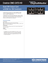
Rack Mounting
The DGE-1 occupies 1U (1.75 inches) of rack space. The DGE-2 occupies 2U (3.5 inches) of rack
space. Two rack ears are supplied to mount the DGE into a rack. To mount the DGE in a rack, refer
to the following illustration and perform the steps listed below:
A. Using a #1 or #2 Phillips screwdriver, remove the three cover screws closest to the front panel
from one side of the device.
B. Position one of the rack ears so its mounting holes align with the three holes vacated in step A.
C. With the DGE-1, secure the ear to the device using the three cover screws removed in step A.
With the DGE-2, secure the ear to the device with three of the six #06-32 x 3/8” screws included
with the DGE-2.
D. Repeat steps A through C to attach the remaining ear to the opposite side.
E. Secure the rack mount ears to the rack using four rack mount screws (two screws each side,
not supplied).
Tabletop Mounting
Rubber feet are provided to mount the DGE onto a tabletop. Apply the feet near the corners on the
underside of the device.
NOTE: For wiring between the DGE and V-Panel, use DM-CBL DigitalMedia™ cable.
The maximum allowable cable length between a DGE-1 and a V-Panel is 150 feet (45 meters).
The maximum allowable cable length between a DGE-2 and V-Panel is 450 feet (137 meters).
NOTE: Throughout this guide, V-Panel™ refers to the V12, V15 and V24R-C HD Touch Screen
Displays unless otherwise noted and DGE refers to the DGE-1 or DGE-2 Digital Graphics Engine.
(6) Cover Screws
(2) Rack Ears
(Supplied)
V-Panel to DGE Connection Using the V-IMCW Interface Module (V12/15 and DGE-1 Shown)
(Supplied with V-Panel VESA Mount and Tilt Models)
Direct Connection Between V-Panel and DGE (V12/15 and DGE-1 Shown)
(V-IMCW Interface Module Not Used)
V12/15 (Bottom View)
DGE-1 (Rear View)
VIDEO IN
COMP/C
Y
AUDIO AUDIO IN
AUDIO OUT
LAN
L
M
TO PANEL
DM OUT
R
+ - G + -
L
R
+ - G + - 24 A B G S G
REMOTE
RESET
SETUP
NET
24 Y Z G 24 Y Z G
D
D
D M
M
24 A B G
V-IMCW Interface Module (Supplied)
D
D
M
24 A B G
M
24 A B G
24 A B G
V-CBL-T
Cable
(Supplied)
DM-CBL
(DGE-1: 150 Feet (45 Meters) Maximum)
(DGE-2: 450 Feet (137 Meters Maximum)
Ground
Wire
DGE Video Input, Audio Input/Output, Contact Closure, LAN, and Ground Connections
(DGE-1 Shown)
DGE-1
(Rear View)
VIDEO IN
COMP/C
Y
AUDIO AUDIO IN
AUDIO OUT
LAN
L
M
TO PANEL
DM OUT
R
+ - G + -
L
R
+ - G + - 24 A B G S G
REMOTE
RESET
SETUP
NET
24 Y Z G 24 Y Z G
D
Ground
DIGITAL
MEDIA OR
ANALOG
DISTRIBUTION
SYSTEM
CONTACT
CLOSURE
LAN
AV
SOURCE
AUDIO
MATRIX
DGE Control and Power Connections (DGE-1 Shown)
V12/15 (Bottom View)
DGE-1 (Rear View)
VIDEO IN
COMP/C
Y
AUDIO AUDIO IN
AUDIO OUT
LAN
L
M
TO PANEL
DM OUT
R
+ - G + -
L
R
+ - G + - 24 A B G S G
REMOTE
RESET
SETUP
NET
24 Y Z G 24 Y Z G
D
M
D M
D
24 A B G
24 A B G
DM-CBL
LAN
SETUP
NET
24 Y Z G 24 Y Z G
LAN
POWER
SUPPLY
CONTROL
SYSTEM
Ethernet
Control
System
DGE-1
(Rear View)
LAN
SETUP
NET
24 Y Z G 24 Y Z G
CONTROL
SYSTEM
CRESNET
DEVICE
Cresnet
®
Control
System
DGE-1
(Rear View)
1
NOTE: The DGE-2 is powered via its built-in IEC socket and comes with a detachable power cord.
V-Panel Connections
On the V12 and V15, HDMI
®
(D port), data management (M port), and power and control
(DMNet
®
24 A B G port) connections are made to the bottom of the V-Panel. The V24-C has a
single DM IN port and requires a DM-TX-201-C transmitter or DM switcher (both sold
separately) for connection to a DGE-2. A USB HID port is also provided on the bottom of the
V-Panels.
• DM Input and 24 A B G Connections (V12 and V15): Connect the DM CAT input,
comprised of two 8-pin RJ-45 connectors (D and M, right to left) to the DM CAT output (D
and M, left to right) of the DGE. Using the supplied terminal block connector, connect the
4-pin DMNet port to the DMNet port of the DGE. If the V-IMCW Interface Module is used,
use the supplied
V-Cable Triamese cable (V-CBL-T) to connect the V-Panel to the front of
the module. Use
DM-CBL to connect the rear of the module to the rear of the DGE.
• DM IN and 24VDC Connections (V24R-C): Connect the DM input, comprised of a single
8-pin RJ-45 connector to the DM output of a DM-TX-201-C transmitter or DM switcher.
Using the supplied terminal block connector, connect the 2-pin 24VDC port to the power
pack included with the DGE-2. If the IMCW-V24-C Interface Module is used, use the
supplied
V-Cable Triamese cable (V-CBL-SC3) to connect the V-Panel to the front of the
module. Use
DM-CBL to connect the rear of the module to the DM-TX-201-C or DM
switcher.
DGE Connections
Video, audio, D and M, DMNet, contact closure, LAN, control, and power connections are made
to the rear of the device. A USB HID port is also provided on the front of the device.
• USB HID Connection: Connect the USB port to a keyboard, mouse, or other USB-HID
compliant device.
• VIDEO IN Connection(s): For video input connection(s), use 75-ohm coaxial cable with
BNC connectors to connect to the video source.
For composite video input, connect the COMP/C connector only.
For S-video (Y/C) input, connect both the COMP/Y and C connectors.
In addition, on the DGE-2 only:
For component video input, connect the Y, P
B
/Y and P
R
/C/COMP connectors.
The DGE-2 also includes RGB and HDMI video inputs.
• AUDIO Connection: Using CresCAT
®
cable, connect the bidirectional Crestron Home
®
CAT5 balanced stereo audio port to any other Crestron Home CAT5 balanced audio port.
The maximum cable length is 1000 feet (305 meters).
• AUDIO IN Connection: Using the supplied terminal block mating connector, connect the
5-pin balanced/unbalanced stereo line level input to the audio input device.
• AUDIO OUT Connection: Using the supplied terminal block mating connector, connect
the 5-pin balanced/unbalanced stereo line level output to the audio output device.
• Ground Connection: Connect the chassis ground lug to earth ground (building steel).
• TO PANEL, DM OUT and 24 A B G Connections (V12/15 only): Refer to the description
of the V-Panel DM INPUT and 24 A B G (DMNet) connections above.
• VIDEO OUT, HDMI (DGE-2 only): For HDMI video and audio connection to a compatible
display device.
• REMOTE RESET Connection: Using the supplied terminal block mating connector,
connect the 2-pin contact closure input for remote reset of the DGE.
• LAN Connection: Using an RJ-45 cable, connect the 8-pin LAN port to the Ethernet
network. In an Ethernet control network, connect the control system to the network.
• NET Connection(s): Using the supplied terminal block mating connector, connect one
of the 4-pin NET ports to the control system in a Cresnet
®
control network or to a
power supply in an Ethernet control network.
When connecting to a power supply, connect only the power pair of wires.
If required, connect the second NET port to a Cresnet device.
• USB HID Connection (Front): Connect the USB port to a keyboard, mouse, or other
USB-HID compliant device. The DGE-2 has two additional USB ports on the rear.

2
quickstart guide
V-Panel™ and DGE
www.crestron.com
888.273.7876 201.767.3400
Specifications subject to
change without notice.
V-Panel and DGE
For details, refer to the latest version of the DGE-1 Digital Graphics Engine Operations Guide, Doc. 6776, DGE-2 Digital
Graphics Engine Operations Guide, Doc. 6809, V12 & V15 V-Panel 12” & 15” HD Touch Screen Displays Operations
Guide, Doc. 6806 and the V24R-C V-Panel HD Touch Screen Displays Operations Guide, Doc. 7327.
QUICKSTART DOC. 6808C (2024098) 08.12
HD Touch Screen Display and Digital Graphics Engine
Uploading the VT Pro-e Project
To upload the SIMPL Windows program to the control system:
A. Locate the sample SIMPL Windows program for the DGE at
www.crestron.com/exampleprograms, and then download the program to the
computer.
B. Modify the program as required:
• To add the DGE as an Ethernet device, do the following:
From the Touchpanels | Touchpanels (Ethernet) folder of the Device
Library, drag the DGE touchpanel into slot 8 of System Views (refer to the
illustration at the top of the next column).
• To add the DGE as a Cresnet device, do the following:
From the Touchpanels | Touchpanels (Cresnet) folder of the Device
Library, drag the DGE touchpanel into slot 9 of System Views (refer to the
illustration at the bottom of the next column).
• (Optional) Double-click the DGE in the system tree to open the “Device
Settings” window, then change the Ethernet IP ID or Cresnet ID of the
DGE.
For additional programming information, refer to the SIMPL Windows
online help.
C. Using Crestron Toolbox™, do the following:
1. From the Tools menu, select System Info.
2. In the Address Book drop-down list, select the desired control system.
3. Click the Quick function access button ( ), then select SIMPL
Program.
4. Browse for the program, select the program, then click Open.
5. Click Send.
The “Confirmation” window opens, asking to overwrite the default IP table
of the control system with the default IP table of the SIMPL Windows
program.
6. Click Yes.
7. In the “SIMPL Program” window, click Close.
NOTE: The DGE—not the V-Panel—is programmed in SIMPL Windows.
Device Library and Sample System Views, DGE-1 (Ethernet) in Slot 8
Device Library and Sample System Views, DGE-1 (Cresnet) in Slot 9
NOTE: The VT Pro-e
®
project is uploaded to the DGE—not to the V-Panel.
Uploading the SIMPL Windows Program
Creating a New Project (Selection of DGE-1_V12 Shown)
NOTE:
Do not close Crestron Toolbox. It must be used in section .
3
NOTE: When creating a new project, be sure to select the correct panel type. The V-Panel that
is to be connected to the DGE must be selected; for example, with a DGE-1, to select the V12,
select DGE-1_V12 as shown in the illustration below.
2
3
NOTE: The following illustrations depict use of a DGE-1. The process is the same when selecting the DGE-2.
To upload the VT Pro-e project to the DGE:
A. Locate the sample VT Pro-e project for the DGE and V-Panel at
www.crestron.com/exampleprograms, then download the program to the computer.
B. (Optional) Do either of the following:
• Modify the sample project, then compile the project.
• Create a new project, then compile the project.
C. Using Crestron Toolbox, do the following:
1. From the Tools menu, select System Info.
2. In the Address Book drop-down list, select the desired DGE.
3. Click the Quick function access button ( ), then select Project.
4. Browse for the project, select the project, then click Open.
5. Click Send All File Types to send the entire compiled project.
6. Click Send to transfer the files. A progress bar displays the status of the transfer as
the project is uploading.
The specific patents that cover Crestron products are listed at patents.crestron.com.
Crestron, the Crestron logo, Crestron Home, Crestron Toolbox, CresCAT, Cresnet, DigitalMedia, DMNet, V-Panel and
VT Pro-e are either trademarks or registered trademarks of Crestron Electronics, Inc. in the United States and/or other
countries. HDMI is a trademark or registered trademark of HDMI Licensing LLC in the United States and/or other countries.
Other trademarks, registered trademarks and trade names may be used in this document to refer to either the entities claiming
the marks and names or their products. Crestron disclaims any proprietary interest in the marks and names of others.
©2011 Crestron Electronics, Inc.
NOTE: The default resolutions for the
different V-Panels are as follows:
•
V12 800 x 600
•
V15 1280 x 768
•
V24-C 1920 x 1200
If desired with the DGE-2, use the “Project
Properties” dialog box to change to a
different resolution after creating the
®
/