DO GUIDE
As of the date of manufacture, the products have been tested and found to comply with specications for CE marking.
This product is Listed to applicable UL Standards and requirements tested by Underwriters Laboratories Inc.
Ce produit est homologué selon les normes et les exigences UL applicables par Underwriters Laboratories Inc.
Federal Communications Commission (FCC) Compliance Statement
This device complies with part 15 of the FCC Rules. Operation is subject to the following two conditions:
(1) This device may not cause harmful interference, and (2) this device must accept any interference received, including interference
that may cause undesired operation.
CAUTION: Changes or modications not expressly approved by the manufacturer responsible for compliance could void the user’s
authority to operate the equipment.
NOTE: This equipment has been tested and found to comply with the limits for a Class B digital device, pursuant to part 15 of the
FCC Rules. These limits are designed to provide reasonable protection against harmful interference in a residential installation.
This equipment generates, uses and can radiate radio frequency energy and, if not installed and used in accordance with the
instructions, may cause harmful interference to radio communications. However, there is no guarantee that interference will not
occur in a particular installation.
If this equipment does cause harmful interference to radio or television reception, which can be determined by turning the
equipment off and on, the user is encouraged to try to correct the interference by one or more of the following measures:
• Reorient or relocate the receiving antenna
• Increase the separation between the equipment and receiver
• Connect the equipment into an outlet on a circuit different from that to which the receiver is connected
• Consult the dealer or an experienced radio/TV technician for help
Industry Canada (IC) Compliance Statement
CAN ICES-3(B)/NMB-3(B)
The products are class 1 laser products. They comply with safety regulations of IEC-60825-1, FDA 21 CFR
1040 11 and FDA 21 CFR 1040 10.
WARNING: Visible and invisible laser radiation when open. Avoid direct exposure to beam.
NOTE: Plug the included dust cap into the optical transceiver when the ber optic cable is unplugged.
The specic patents that cover Crestron products are listed at patents.crestron.com. The product warranty can be found at www.crestron.com/warranty.
Crestron, the Crestron logo, Crestron Toolbox, DigitalMedia, DigitalMedia 8G, and DM are either trademarks or registered trademarks of Crestron Electronics, Inc. in the United States and/or
other countries. HDMI is either a trademark or registered trademark of HDMI Licensing LLC in the United States and/or other countries. UL and the UL logo are either trademarks or registered
trademarks of Underwriters Laboratories, Inc. in the United States and/or other countries. Other trademarks, registered trademarks, and trade names may be used in this document to refer
to either the entities claiming the marks and names or their products. Crestron disclaims any proprietary interest in the marks and names of others. Crestron is not responsible for errors in
typography or photography.
This document was written by the Technical Publications department at Crestron.
©2016 Crestron Electronics, Inc.
DOC. 7758B (2043305) 11.16
Specications subject to change without notice.
DO Set the IP Address
The conguration of the transmitter within the Crestron
®
DigitalMedia 8G™ system determines
how the IP address of the transmitter is set:
• If the transmitter connects to a DigitalMedia™ switcher, the transmitter is congured by the
switcher automatically.
• If the transmitter connects to a DigitalMedia 8G ber receiver, the transmitter uses its own
conguration settings. By default, DHCP (Dynamic Host Conguration Protocol) is enabled.
If it is desired that the default IP address be assigned to the transmitter, hold down the
SETUP button while the unit boots up. The default IP address 192.168.1.237 overwrites
the current setting. To manually set a different IP address, use the Crestron Toolbox™
application.
DO Learn More
Visit the website for additional information and the latest rmware updates. To learn
more about this product, use a QR reader application on your mobile device to scan
the QR image.
Crestron Electronics
15 Volvo Drive, Rockleigh, NJ 07647
888.CRESTRON | www.crestron.com
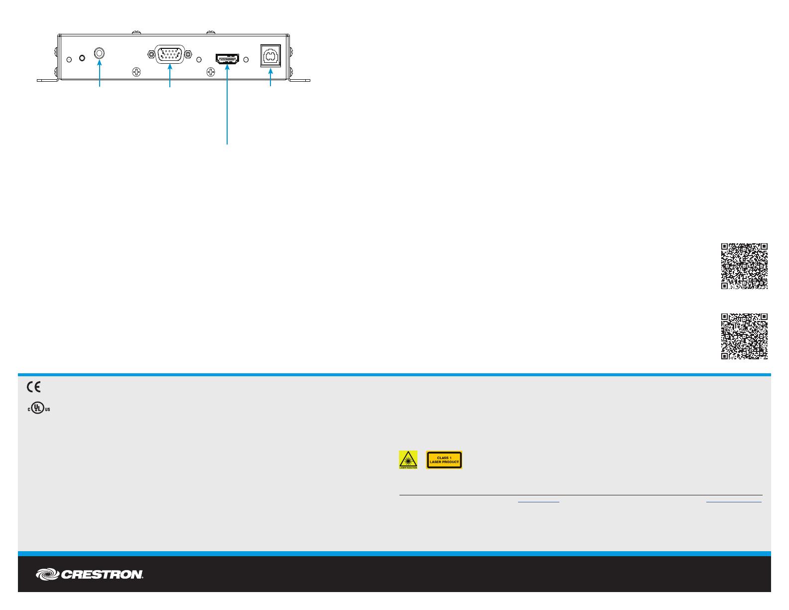
DM-T X-201-S
DM-T X-201-S2
USB HID:
From USB host
interface of USB
HID-compliant
host device
HDMI IN:
HDMI
digital
video/audio input
RGB IN:
RGB (VGA),
component,
S-video, or
composite
video input
AUDIO IN:
Unbalanced stereo
line level input
Connections to the DM-TX-201-S and DM-TX-201-S2 Rear Panel

