Page is loading ...

Grandstream Networks, Inc.
GWN78xx Series
GWN78xx – Link Aggregation Guide

GWN78XX(P) - Link Aggregation Guide
Overview
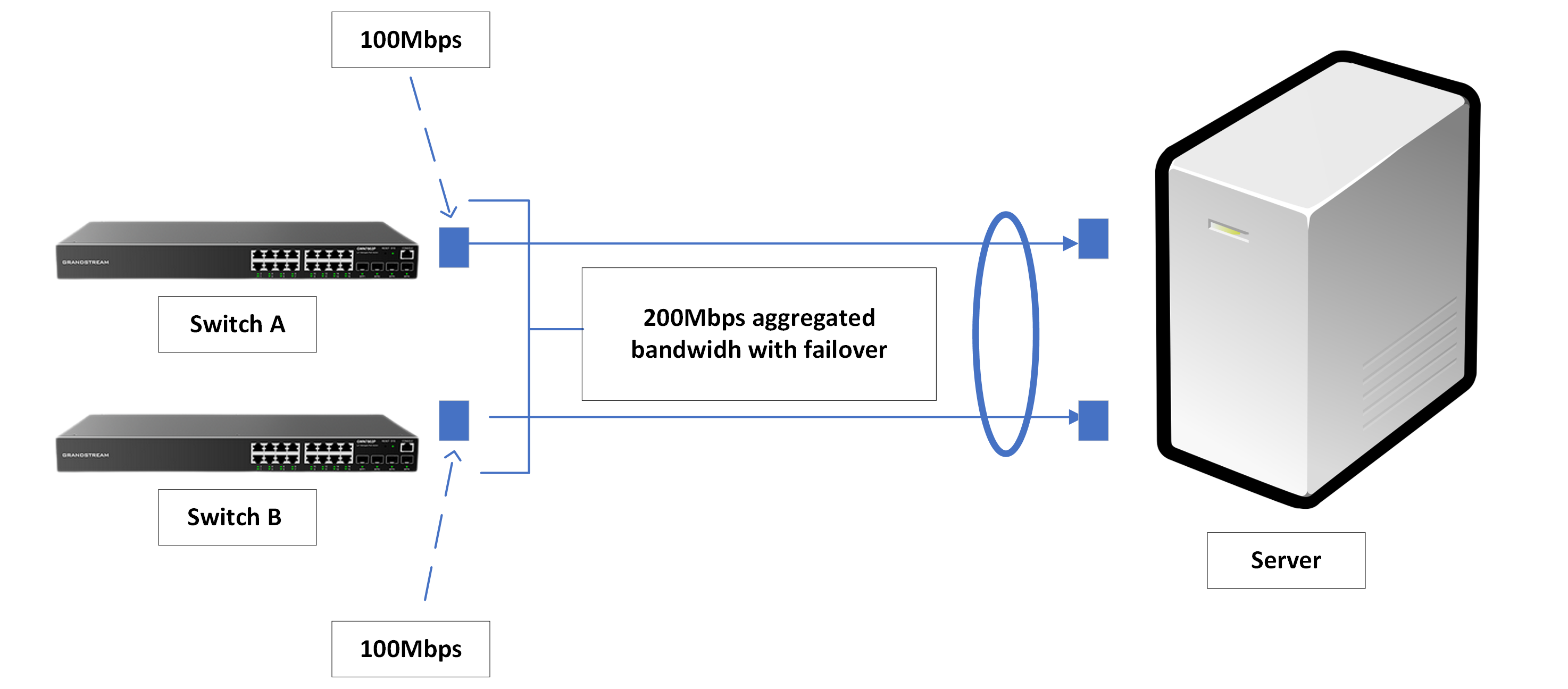
Link aggregation, also known as port aggregation or NIC teaming, is a technique used in layer 2 and layer 3 network switches
to combine multiple physical links into a single logical link. This logical link provides increased bandwidth, redundancy, and
load balancing.
Link aggregation diagram
The two main goals for creating link aggregation groups are :
Enhancing the overall bandwidth beyond the capabilities of a single link by distributing traffic across the member ports.
Increasing the reliability of the connection as the member ports dynamically back each other up. This means that if one
port fails, the traffic is automatically routed to other member ports, ensuring uninterrupted network connectivity.
Link Aggregation Configuration Example
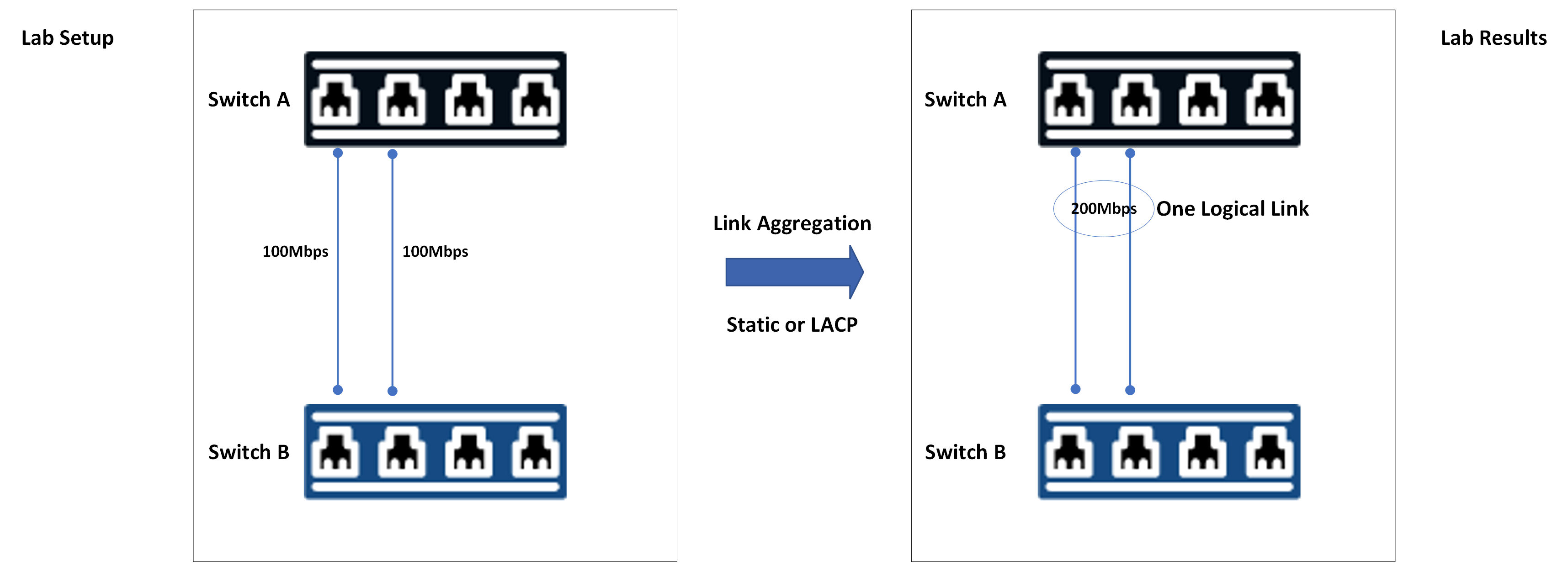
In this section of the guide, we will create a lab to combine two network connections into a single aggregated logical link. To
accomplish this, we will use two Grandstream network switches.
Link Aggregation setup
We will go about two methods to do it :
Static Link Aggregation
LACP (Link aggregation Control Protocol)

Static Link Aggregation Configuration
Static link aggregation is a manual configuration where both the switch and the host are required to recognize the LAGs.
Because this setup is static, there is no additional protocol to assist the switch and host in recognizing issues such as
incorrectly connected cables, which could lead to LAG failure.
To configure a static link aggregation on GWN78xx network switches, please follow the below steps:
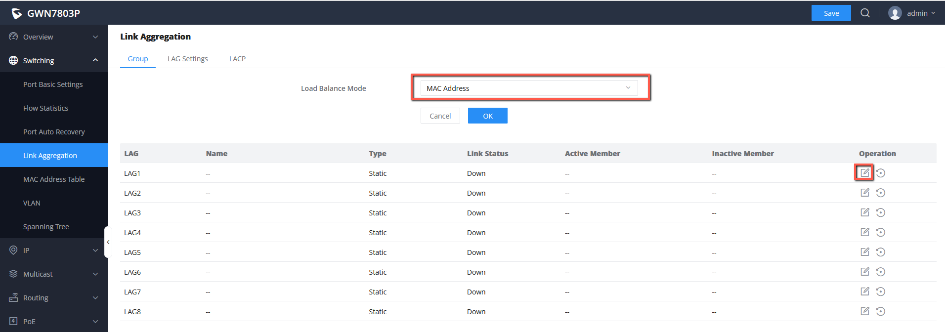
1. On the first switch (Switch A), navigate to Web UI → Switching → Link Aggregation → Group, then select the Load
Balance mode to MAC Address.
2. We will configure LAG1 to be our static Link aggregation group, to do that click the icon to edit the LAG,
Choosing Load Balance mode and Editing LAG1
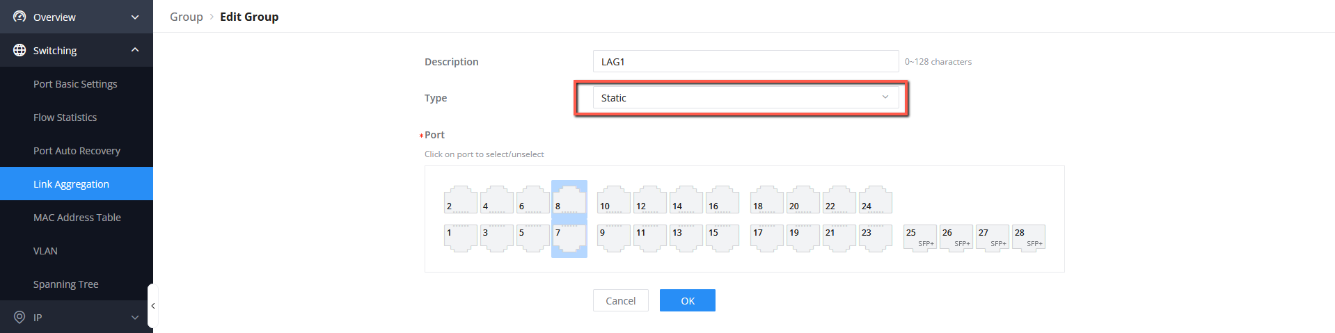
3. Choose a Name for the Link Aggregation group and then Select the LAG category. The LAG type will be set to Static.
Following that, choose the ports that will be used in conjunction with other switch ports to aggregate bandwidth or provide
dynamic backup, when done Click “OK” and then save the changes.
Setting up the LAG1 on Switch A
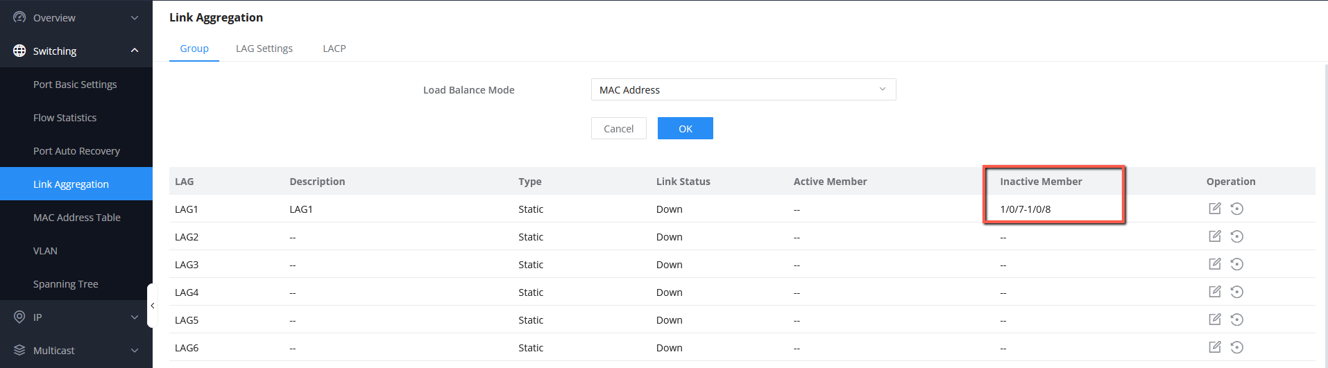
4. The members of the LAG1 will be shown under the Inactive member section, once the ports are plugged, they will be
shown under the Active member section.
Notes
Before we start configuring both switches, please make sure you review the following information:
A logical link can bundle up to 8 ports.
A port that is part of a link aggregation group should not have any form of authentication applied to it (NAC authentication
for example).
The bundled ports must have the same speed and duplex.
LAG configuration is automatically applied to the port.
Switching protocols should be applied to the LAG.
The same Link Aggregation type (LACP or static) must be configured on both sides of the link.
Always Configure LAG before connecting the cables: Using multiple Ethernet cables between two devices between LAG is
created can cause a bridging loop especially when the spanning tree is disabled.

Setting Inactive members
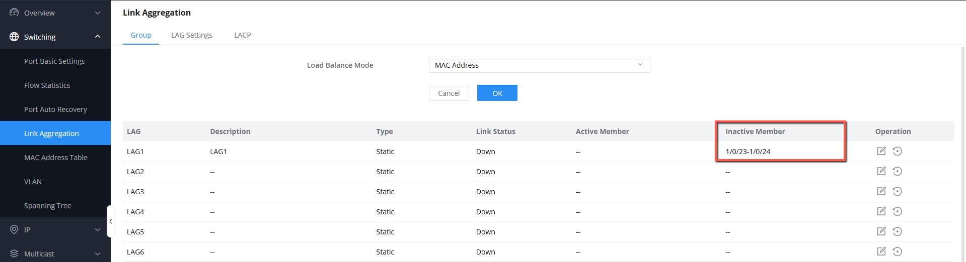
5. Using the identical process, create LAG1 on the second switch (Switch B), which will be combined with our primary switch.
Once configured, the Switch B Web UI will show the following results:
LAG1 created on Switch B
LACP Configuration
LACP dynamically recognizes links created between the switch and the host, allowing the LAG to be formed automatically.
This functionality is supported by all server-class switches; however, network administrators must enable LACP on the switch
port.
We will now configure on both switches A and B a LAG using LACP, to do that please follow the below steps:
1. Under Web UI → Switching → Link Aggregation → Group, select the Load Balance Mode to MAC Address based.
2. LAG2 will be set to an LACP, to do that click the icon to edit the Link Aggregation group:
Edit LAG2
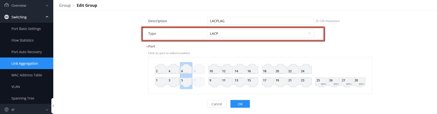
3. Name the group “LACPLAG”, and then set the type to “LACP”, then select the ports that will be part of “LACPLAG”, please
bear in mind that you can not select ports that were already added to a different LAG (eg: 1/0/7 and 1/0/8 are already part of
LAG1), in our case we will select port 1/0/5 and 1/0/6, once Selected, Click “OK” then Save.

Select LAG type
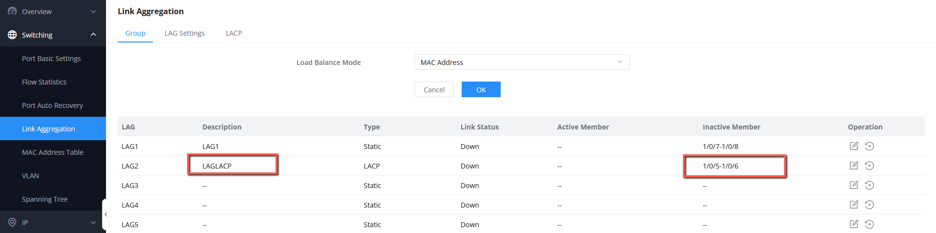
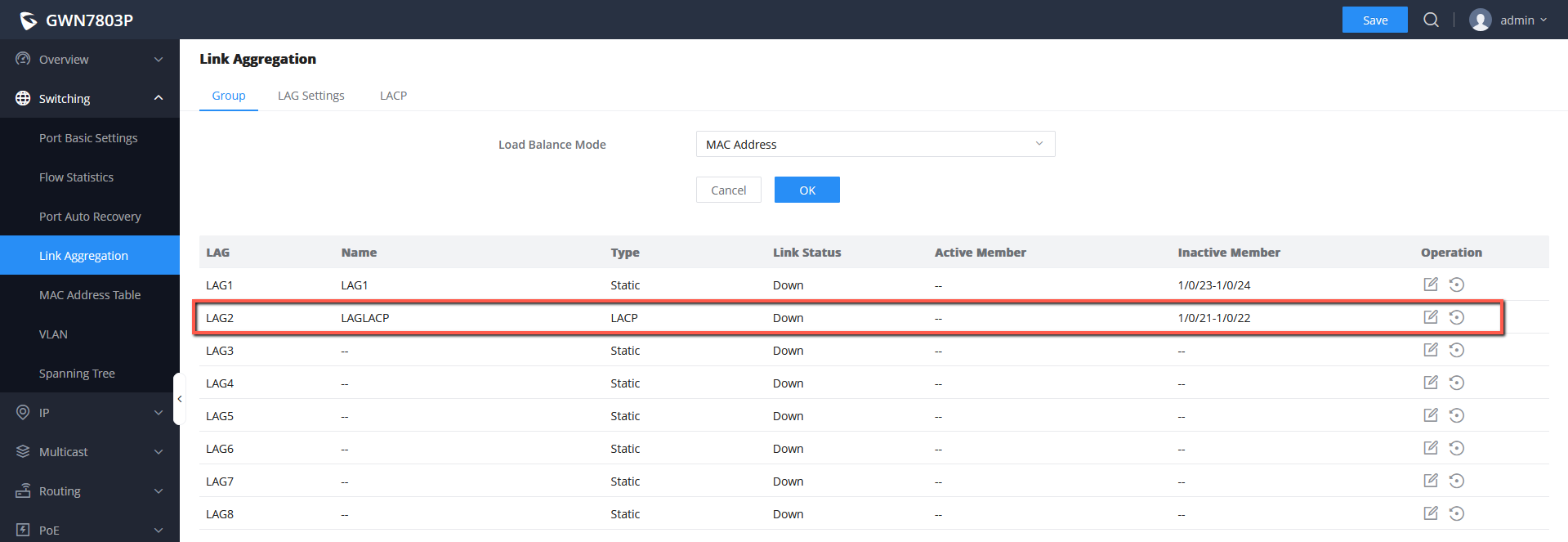
4. After the “LACPLAG” is created, it will be shown on the list of Link aggregation groups with their respective ports, they will
be in the Inactive member section, and once the cables are plugged they will be under Active member.
Verifying that LAG2 is created
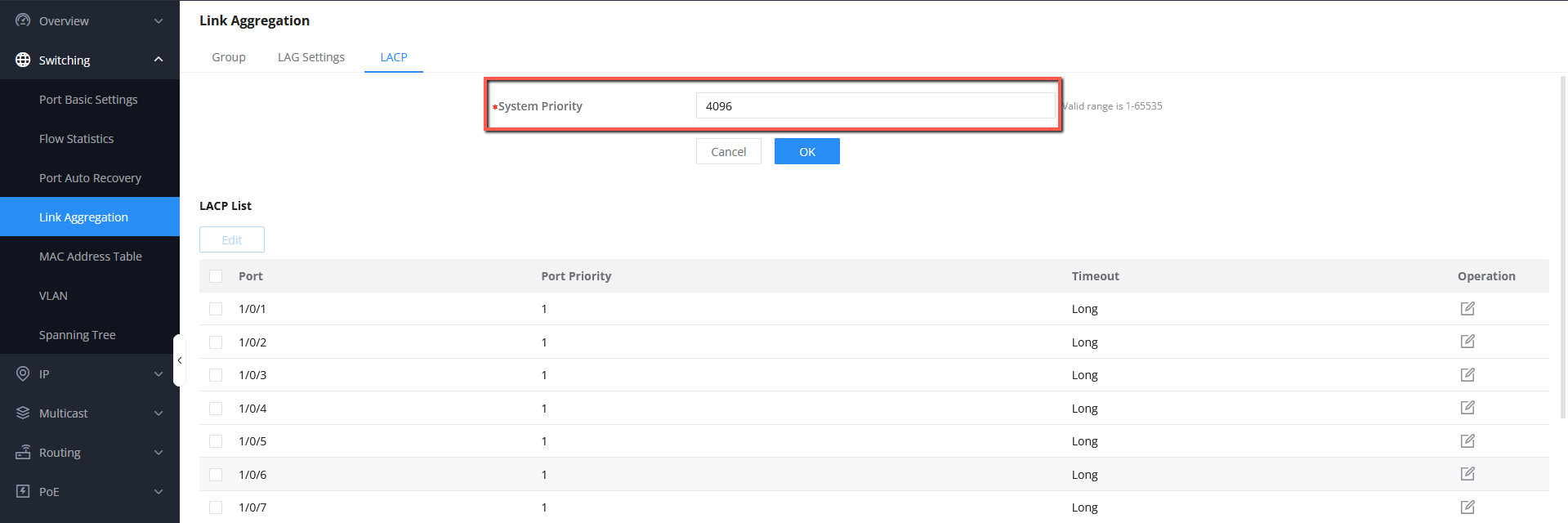
5. After the LAG is created, go to LACP settings under Switching → Link Aggregation → LACP, then change the system
priority to a lower value than the default one (32768), we will set the value for example 4096.
System Priority Settings
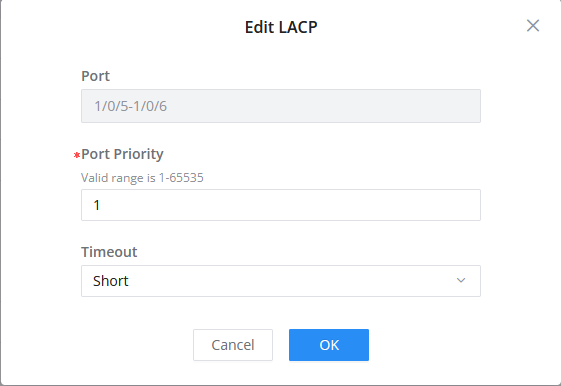
6. Select the ports 1/0/5 and 1/0/6 that are part of the LAGLACP then click “Edit”, after that you can configure the port priority
and the timeout to be set to either Long or Short. We will set both ports to have a Short timeout.
Information
In order to control and make decisions about the ports that will be actively participating in the link aggregation, we need to set
a lower value. A lower value equals a higher priority.
Information
Long Timeout: The switch will send LACPDU notifications every 30 seconds and if there is no response after 90 seconds (3
LACPDUs), it will terminate LACP on the port.
Short Timeout: The switch will send LACPDU every 1 second and if there is no response after 3 seconds (3 LACPDUs), it will
terminate LACP on the port.
Port Priority: The Port priority can be defined if more than one LACP LAG are created on the network, if we want to
differentiate between them by priority, the ports with lower priority value to have the highest priority.

Edit LACP ports
7. We will repeat the same steps on Switch B, to set up ports 1/0/21 and 1/0/22 as LAGLACP, the only difference is that we will
keep the system priority to its default value (32768), that way we have Switch A with lower priority to make decisions about
the designated ports.
Creating LACPLAG on Switch B
Finally, once the cables are plugged into both Switches’ ports, the links will be aggregated.
Verifying the Creation of the LAG
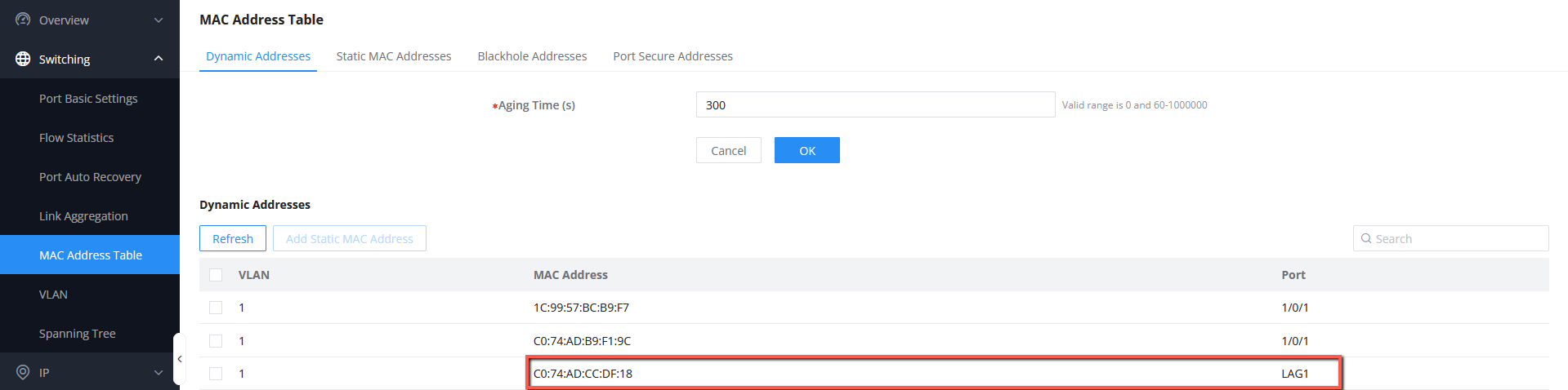
Once the LAG is created, it will be assigned a logical MAC Address and will be shown in the Dynamic MAC Address table,
under Switching → MAC Address Table:
MAC Address verification
Verifying the Aggregated Speed
After Plugging both ports, the results should be as follows :
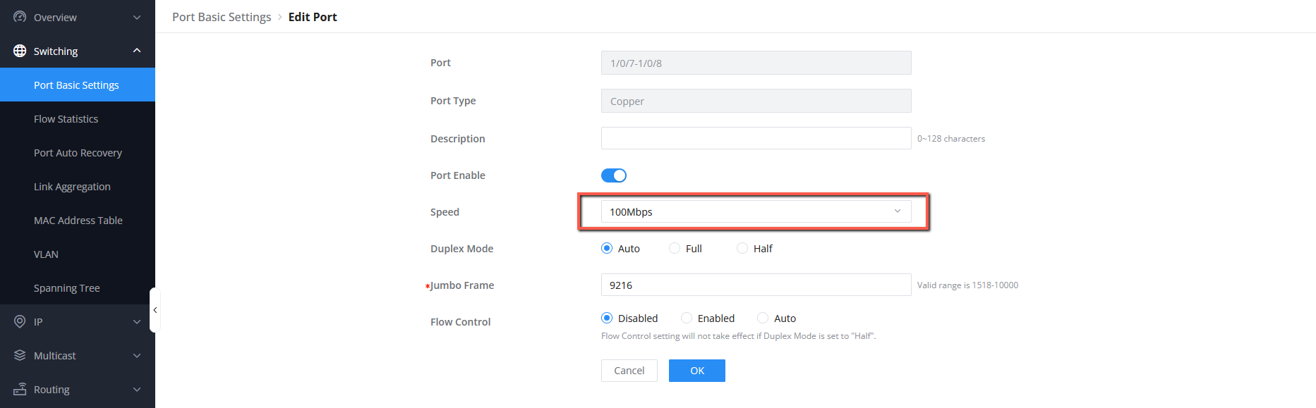
1. First, for the purpose of this test, we will limit the speed of all four ports that are part of LAG1 on both Switch A and
Switch B to 100 Mbps, this will include ports 1/0/7, 1/0/8 on Switch A and port 1/0/23, 1/0/24 on Switch B, to do so

under Switching → Port Basic settings, select the desired ports and set the speed to 100 Mbps as shown below, after
that click “OK”, then “Save”
Setting the speed for ports
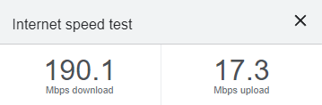
2. Since we are plugging two Ethernet links with 100 Mbps each, the aggregated final outputted bandwidth should be 200
Mbps theoretically, please bear in mind that the internet speed will be limited to the max speed that you receive from your
internet service provider and to how congested your network is, to verify the final Internet bandwidth coming from the
aggregated link (LAG1 for example), you can use the default internet speed tester on your browser for the connection that is
coming from either a direct wired connection to your laptop or from a connected Wireless access point on the network.
An example will be :
Internet Speed
Supported Devices
Note
Please make sure that you configure the speed of the ports before plugging the cables in and also make sure that ports 1/0/1,
1/0/2 on switch A and ports 1/0/23, 1/0/24 on switch B all have the same speed of 100 Mbps.
Device Name Supported Number of LAGs supported Firmware Required
GWN7801 Yes 8 LAGs 1.0.1.20 or higher
GWN7801P Yes 8 LAGs 1.0.1.20 or higher
GWN7802 Yes 8 LAGs 1.0.1.20 or higher
GWN7802P Yes 8 LAGs 1.0.1.20 or higher
GWN7803 Yes 8 LAGs 1.0.1.20 or higher
GWN7803P Yes 8 LAGs 1.0.1.20 or higher
GWN7811 Yes 5 LAGs 1.0.1.8 or higher
GWN7811P Yes 5 LAGs 1.0.1.8 or higher

Need Support?
Can’t find the answer you’re looking for? Don’t worry we’re here to help!
CONTACT SUPPORT
List of Supported Devices
GWN7812P Yes 10 LAGs 1.0.1.8 or higher
GWN7813 Yes 14 LAGs 1.0.1.8 or higher
GWN7813P Yes 14 LAGs 1.0.1.8 or higher
GWN7806 Yes 27 LAGs 1.0.1.14 or higher
GWN7806P Yes 27 LAGs 1.0.3.3 or higher
GWN7830 Yes 6 LAGs 1.0.3.3 or higher
GWN7831 Yes 14 LAGs 1.0.3.3 or higher
GWN7832 Yes 6 LAGs 1.0.3.3 or higher
/