Page is loading ...

StrongSlide™ M50
Installation Instructions

2support.hysecurity.com
Visit support.hysecurity.com for Installation manuals, replacement part instructions, part diagrams and more.
Contents
Safety Requirements ...................................................................................................................................2
Plan Site Design ..........................................................................................................................................3
Prepare Foundation .....................................................................................................................................4
Assemble Rebar .....................................................................................................................................5 - 6
Install Rebar ................................................................................................................................................7
Install Conduit in Rebar ...............................................................................................................................8
Pre-Assemble Anchors ................................................................................................................................9
Assemble Anchor Supports .......................................................................................................................10
Locate Anchors .......................................................................................................................................... 11
Finish Anchor Assemblies..........................................................................................................................12
Secure Anchors and Supports ...................................................................................................................13
Pour Concrete ...........................................................................................................................................14
Install Arrestor Posts..................................................................................................................................15
Install Gate Supports .................................................................................................................................16
Adjust Clearances .....................................................................................................................................17
Fill Arrestor Posts ......................................................................................................................................18
Mount SlideDriver ......................................................................................................................................19
Mount Panels and Signs............................................................................................................................20
Safety Requirements
DANGER
Refer to UL 325, ASTM F2200, and SlideDriver operation manual for complete safety information. Failure to follow the
instructions and safety information may result in death or serious injury.
The StrongSlide automatic vehicular gate system is designed for UL 325 Usage Class IV installations only. A SlideDriver
installed on a StrongSlide gate is restricted to Usage Class IV only.
It is the responsibility of the system designer and/or installer ensure any safety or operational issues have been addressed.*
*Disclaimer: All gate installations using HySecurity vehicular gate operators must comply with UL325 and ASTM F2200 safety
standards in addition to any local area codes and standards. Site, gate hardware, usage class, and other conditions
will dictate the use of additional safety designs and components. All safety related warnings and notices in this
document, and any diagrams, drawings, photographs and similar content should not be considered guidance on how
to make your particular site safe and code compliant. It is the responsibility of the gate system designer, installer and
owner to assess appropriate safety design considerations, correct implementation and ongoing maintenance of any
system.

3
MX5672 Rev. A ©2023
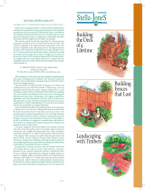
CLEAR OPEN (FT)
B
15.2
6.0
G
10.2
4.0
FULL ASSEMBLY VIEW:
ATTACK DIRECTION
**
** StrongSlide-M50 tested at 24 ft clear opening per ASTM F2656-20.
CLEAR
OPEN
G
B
Gate Weight
ft (cm)
inch (cm) inch (cm) lb (kg)
12 (366)
243 (617)
40.5 (103)
900 (408)
13 (396)
255 (648)
40.5 (103)
950 (431)
14 (427)
267 (678)
40.5 (103)
1000 (454)
15 (457)
279 (709)
40.5 (103)
1045 (474)
16 (488)
291 (739)
40.5 (103)
1080 (490)
17 (518)
303 (770)
40.5 (103)
1155 (524)
18 (548)
318 (808)
43.5 (110.5)
1200 (544)
19 (579)
333 (846)
46.0 (117)
1250 (567)
20 (610)
348 (884)
49.5 (125.5)
1310 (594)
21 (640)
363 (922)
52.5 (133.5)
1350 (612)
22 (671)
378 (960)
55.5 (141)
1425 (646)
23 (701)
396 (1006)
61.5 (156)
1470 (667)
24 (731.5)
414 (1052)
67.5 (171.5)
1525 (692)
PROPRIETARY INFORMATION OF
HY-SECURITY GATE, INC.
This document, and the information contained herein, are the confidential, proprietary and trade secret information of Hy-Security Gate, Inc. ("Hy-Security"). Any party receiving, accepting or
retaining this document thereby agrees to use the document, and any information contained therein, solely as may be required to manufacture products or components for Hy-Security and will
not provide this document or any information therein to any other party, or use if for any other purposed, without the express, prior, written consent of Hy-Security.
StrongSlide M50: Plan Site Design
Note: Determine roadway width and plan for additional clearances to install StrongSlide.

4support.hysecurity.com
243.8
96.0
L
243.8
96.0
A
121.9
48.0
A A
1
91.4
+
7.6
0.0
36.0
+
-
3.0
.0
1
91.4
+
7.6
0.0
36.0
+
-
3.0
.0
2
137.2
54.0
SECTION A-A
SCALE 1 : 84
137.2
54.0
137.2
54.0
518.2
204.0
137.2
54.0
137.2
54.0
701.0
276.0
2
4
2
NOTES:
PER ASTM F2656 SECTION 7.2.2, "Soil shall be low-cohesive, well-graded crushed stone or broken gravel of a
1.
particle size distribution comparable to Table 3" "Soil shall have a depth equal to the bottom of the foundation
and width equal to 1.5 times the foundation depth behind the barrier"
- Foundation depth is 36" (91.4cm), therefore all specified perimeter soil must match this 36" (91.4cm) depth.
- Width of specified soil must be 54" (137.2cm) to each side of the foundation. (36" * 1.5 = 54")
"The low-cohesive soil shall be compacted to a density of not less than 90% maximum dry density in accordance
2.
with Test Methods D1556 and D6938 and AASHTO Method of Test T099 and meet Table 3 for gradation.
ASTM F2656 Table 3:
3.
RECOMPACT SOIL IF FOUNDATION FLOOR IS DISTURBED.
4.
FOUNDATION PREPERATION
**
CLEAR
OPEN
FOUNDATOIN
SPAN ' L '
A
ft (cm)
inch (cm) inch (cm)
12 (366)
43.0 (109)
45.0 (114.5)
13 (396)
55.0 (140)
45.0 (114.5)
14 (427)
67.0 (170)
45.0 (114.5)
15 (457)
79.0 (200.5) 45.0 (114.5)
16 (488)
91.0 (231)
45.0 (114.5)
17 (518)
103.0 (261.5)
45.0 (114.5)
18 (548)
115.0 (292)
48.0 (122)
19 (579)
127.0 (322.5)
51.0 (129.5)
20 (610)
139.0 (353)
54.0 (137)
21 (640)
151.0 (383.5)
57.0 (145)
22 (671)
163.0 (414)
60.0 (152.5)
23 (701)
175.0 (444.5)
66.0 (167.5)
24 (731.5)
187.0 (475)
72.0 (183)
PROPRIETARY INFORMATION OF
HY-SECURITY GATE, INC.
This document, and the information contained herein, are the confidential, proprietary and trade secret information of Hy-Security Gate, Inc. ("Hy-Security"). Any party receiving, accepting or
retaining this document thereby agrees to use the document, and any information contained therein, solely as may be required to manufacture products or components for Hy-Security and will
not provide this document or any information therein to any other party, or use if for any other purposed, without the express, prior, written consent of Hy-Security.
** StrongSlide-M50 tested at 24 ft clear opening per ASTM F2656-20.
StrongSlide M50: Prepare Foundation

5
MX5672 Rev. A ©2023
StrongSlide M50: Assemble Rebar
Note: Rebar and lumber not included.

6support.hysecurity.com
StrongSlide M50: Assemble Rebar
Note: Rebar and lumber not included.

7
MX5672 Rev. A ©2023
63.5
25.0
63.5
25.0
63.5
25.0
55.9
22.0
63.5
25.0
55.9
22.0
E E
G
CUT AREA FOR ANCHOR TEMPLATE
(TOP REBAR LEVEL ONLY)
6
6
1
H
SECTION E-E
SCALE 1 : 84
7.6
3.0
SOIL EDGE
TO REBAR
7.6
3.0
SOIL EDGE
TO REBAR
DETAIL G
SCALE 1 : 15
CENTER REBAR
WITHIN BORE
{WT. EACH = 525 lb (238 kg)}
{WT. EACH = 218 lb (99 kg)}
NOTES:
1. REFER TO DRAWING MX5311 FOR REBAR CAGE CONSTRUCTION DETAILS.
ASSEMBLY, SET AND ALIGN REBAR
7.6
3.0
7.6
3.0
ON HORIZONTAL REBAR
DETAIL H
SCALE 1 : 15
USE BLOCKS TO SPACE
REBAR CAGE ABOVE DIRT
ITEM PART NUMBER DESCRIPTION
QTY.
1
SOIL
REFER TO 'FOUNDATION PREPERATION'
1
2
MX5311-01
REBAR CAGE, SSLIDE-M50, 8'X8'X36"D
2
6
MX5311-02
REBAR CAGE, SSLIDE-M50, GATE POST
1
PROPRIETARY INFORMATION OF
HY-SECURITY GATE, INC.
This document, and the information contained herein, are the confidential, proprietary and trade secret information of Hy-Security Gate, Inc. ("Hy-Security"). Any party receiving, accepting or
retaining this document thereby agrees to use the document, and any information contained therein, solely as may be required to manufacture products or components for Hy-Security and will
not provide this document or any information therein to any other party, or use if for any other purposed, without the express, prior, written consent of Hy-Security.
StrongSlide M50: Install Rebar

8support.hysecurity.com
67.3
26.5
108.0
42.5
87.6
34.5
19.1
7.5
111.8
44.0
67.3
26.5
CD
CD
CONDUIT
UNDER SLIDEDRIVER
CONDUIT
TAIL END CATCH
CONDUIT
LEAD END CATCH
CONDUIT TEE JOINT 3CONDUIT 90 JOINT 3
1
5.1
2.0
MIN
2
12.7
5.0
MIN
67.3
26.5
SECTION CD-CD
SCALE 1 : 24
(Both Foundations)
3
4
4
ADD CONDUIT FOR PHOTO EYE, EDGE, OR SIGNAL LIGHT
NOTES:
RUN CONDUIT BETWEEN FOUNDATION BLOCKS JUST OUTSIDE OF THE CONCRETE.
1
USE TEE & 90 JOINTS TO CONNECT WITH CONDUIT STUBS RUNNING PERPENDICULAR
2
FROM THE ARRESTOR POSTS.
POSITION CONDUIT RUNS FROM THE ARRESTOR BELOW THE TOP ROW OF REBAR OR ~
3
5.0" BELOW CONCRETE SURFACE. WIRE TIE CONDUIT TO REBAR TO HOLD POISTION
DURING CONCRETE POUR.
REFERENCE: CONDUIT LOCATIONS AT BASE OF THE ARRESTOR POSTS.
4
ITEM PART NUMBER DESCRIPTION
QTY.
LOCATION
1
MX5390-XX5
CONDUIT, 3/4", SCH.40
2
ARRESTOR TO EDGE
2
MX5390-XX6
CONDUIT, 3/4", SCH.40
1
SPAN BETWEEN FOUNDATIONS
3
MX5390-XX7
CONDUIT, 3/4", SCH.40
1
OPERATOR TO TAIL END POST
PROPRIETARY INFORMATION OF
HY-SECURITY GATE, INC.
This document, and the information contained herein, are the confidential, proprietary and trade secret information of Hy-Security Gate, Inc. ("Hy-Security"). Any party receiving, accepting or
retaining this document thereby agrees to use the document, and any information contained therein, solely as may be required to manufacture products or components for Hy-Security and will
not provide this document or any information therein to any other party, or use if for any other purposed, without the express, prior, written consent of Hy-Security.
StrongSlide M50: Install Conduit in Rebar

9
MX5672 Rev. A ©2023
ASSEMBLE ANCHOR TEMPLETE HARDWARE
(MINIMAL HARDWARE FOR EASE OF INSTALLATION)
3/4" GATE POST HARDWARE
(4X PER POST, 6X TROLLY-XL)
NOTES:
PLACE SPACERS AT ALL ANCHORS IN POSITIONS AS SHOWN. SPACERS
1.
INCLUDED IN KIT MX5563-02.
SEE ANCHOR ASSEMBLY KIT MX5315-XX FOR HARDWARE DETAILS.
2.
38.1
15.0
.750
5.1
+
0.6
0.0
2.00
+
-
.25
.00
NUT
WASHER
SPACER
1
TEMPLATE
6.4
+
0.6
0.0
2.50
+
-
.25
.00
61.0
24.0
1.00
NUT
WASHER
SPACER
1
TOP TEMPLATE
BTM TEMPLATE
BOLT HEAD
1" ARRESTOR BOLTS
(10X PER TEMPLATE)
PROPRIETARY INFORMATION OF
HY-SECURITY GATE, INC.
This document, and the information contained herein, are the confidential, proprietary and trade secret information of Hy-Security Gate, Inc. ("Hy-Security"). Any party receiving, accepting or
retaining this document thereby agrees to use the document, and any information contained therein, solely as may be required to manufacture products or components for Hy-Security and will
not provide this document or any information therein to any other party, or use if for any other purposed, without the express, prior, written consent of Hy-Security.
StrongSlide M50: Pre-Assemble Anchors

10 support.hysecurity.com
ASSEMBLE TEMPLATE SUPPORT FRAMES
* LH SHOWN
CN
4
7
8
1
3
4
NOTE:
1
ITEM PART OF INSTALLATION KIT MX5563-02
2
ATTACH 2X4s TO TEMPLATES WITH BRACKETS;
APPROXIMATE LENGTHS SHOWN ON THE NEXT PAGE.
3
NAIL CROSS BOARDS TO HOLD SPAN DIMENSIONS.
8
4
4
3
DETAIL CN
SCALE 1 : 4
MX5370
14X
MX5371
28X
1
ITEM PART NUMBER DESCRIPTION
QTY.
1
MX5315-XX
KIT, ANCHOR, SSLIDE-M50, XL
1
2
MX5563-02
KIT, INSTALL, SSLIDE-M50
1
3
WOOD, 2X4
BOARD, 2X4, 12FT
4
4
WOOD, 2X4
BOARD, 2X4, 2.5FT
7
7
WOOD, 2X4
BOARD, 2X4, 10FT
1
8
WOOD, 2X4
BOARD, 2X4, 6FT
3
PROPRIETARY INFORMATION OF
HY-SECURITY GATE, INC.
This document, and the information contained herein, are the confidential, proprietary and trade secret information of Hy-Security Gate, Inc. ("Hy-Security"). Any party receiving, accepting or
retaining this document thereby agrees to use the document, and any information contained therein, solely as may be required to manufacture products or components for Hy-Security and will
not provide this document or any information therein to any other party, or use if for any other purposed, without the express, prior, written consent of Hy-Security.
StrongSlide M50: Assemble Anchor Supports
Note: Rebar and lumber not included.

11
MX5672 Rev. A ©2023
4
SPAN ' X '
0.25 [0.64cm]
4X
53.3
21.0
53.3
21.00
124.5
49.00
124.5
49.0
31.1
12.25
127.0
50.0
37.7
14.8
188.0
74.0
188.0
74.0
127.0
50.0
B
0.50" [1.3cm]
38.7
15.25
1
(WT. ~ 130 lb (59 kg)
(WT. ~ 120 lb (54.4 kg)
1
NOTES:
NAIL SHORT 2X4 SECTIONS TO ACHIEVE BOARD GAP SHOWN.
1.
USE A LEVEL TOOL TO VERIFY ALL TEMPLATE SURFACES ARE LEVEL. SHIM BETWEEN BOARDS
2.
AND SOIL TO ACHIEVE LEVEL ACROSS ALL SPANS.
USE STRING LINE TO ALIGN Y AXIS POINTS BETWEEN TEMPLATES. IF OFF MORE +/- 0.25"(0.64cm),
3.
THERE MAY BE POTENTIAL INTERFERENCE ISSUES WITH GATE AND ARRESTOR SYSTEMS.
MEASURE DISTANCE AT TEMPLATE EDGE TO VERIFY X AXIS SPAN.
4.
DRIVE REBAR INTO SOIL NEXT TO 2X4s TO SECURE POSITIONS DURING CONCRETE POUR.
5.
X
Y
1
8
3X
22
3
1
2
(WT. ~ 32 lb (14.5 kg)
**
PLACE AND ALIGN TEMPLATE FRAMEWORK WITHIN FOUNDATION & REBAR
* LH SHOWN
CLEAR OPEN
SPAN ' X '
B
ft (cm)
inch (cm) inch (cm)
12 (366)
143.0 (363.2)
40.5 (103)
13 (396)
155.0 (393.7)
40.5 (103)
14 (427)
167.0 (424.2)
40.5 (103)
15 (457)
179.0 (454.7)
40.5 (103)
16 (488)
191.0 (485.1)
40.5 (103)
17 (518)
203.0 (515.6)
40.5 (103)
18 (548)
215.0 (546.1)
43.5 (110.5)
19 (579)
227.0 (576.6)
46.0 (117)
20 (610)
239.0 (607.1)
49.5 (125.5)
21 (640)
251.0 (637.5)
52.5 (133.5)
22 (671)
263.0 (668.0)
55.5 (141)
23 (701)
275.0 (698.5)
61.5 (156)
24 (731.5)
287.0 (729.0)
67.5 (171.5)
ITEM
PART NO.
DESCRIPTION
QTY.
1
MX5645-XX
KIT, ANCHOR, SSLIDE-M50
1
8
WOOD, 2X4
BOARD, 2X4, 2.5FT
3
PROPRIETARY INFORMATION OF
HY-SECURITY GATE, INC.
This document, and the information contained herein, are the confidential, proprietary and trade secret information of Hy-Security Gate, Inc. ("Hy-Security"). Any party receiving, accepting or
retaining this document thereby agrees to use the document, and any information contained therein, solely as may be required to manufacture products or components for Hy-Security and will
not provide this document or any information therein to any other party, or use if for any other purposed, without the express, prior, written consent of Hy-Security.
** StrongSlide-M50 tested at 24 ft clear opening per ASTM F2656-20.
StrongSlide M50: Locate Anchors

12 support.hysecurity.com
ASSEMBLE ANCHOR TEMPLETE HARDWARE
- INSTALL REMAINING HARDWARE.
- MAY REQUIRE ADJUSTING REBAR POSITIONS.
3/4" GATE POST HARDWARE
(4X PER TEMPLATE)
3/4" TROLLY HARDWARE
(6X PER TEMPLATE)
3/4" GATE RAMP
HARDWARE (4X)
NOTES:
PLACE SPACERS AT ALL ANCHORS IN POSITIONS AS SHOWN. SPACERS
1.
INCLUDED IN KIT MX5563-02.
SEE ANCHOR ASSEMBLY KIT MX5315-XX FOR HARDWARE DETAILS.
2.
5.1
+
0.6
0.0
2.00
+
-
.25
.00
.750
38.1
15.0
NUT
WASHER
SPACER
1
TEMPLATE
NUT
38.1
15.0
10.2
+
0.6
0.0
4.00
+
-
.25
.00
.750
NUT
NUT
NUT
WASHER
WASHER
SPACER
1
SPACER
TEMPLATE
PROPRIETARY INFORMATION OF
HY-SECURITY GATE, INC.
This document, and the information contained herein, are the confidential, proprietary and trade secret information of Hy-Security Gate, Inc. ("Hy-Security"). Any party receiving, accepting or
retaining this document thereby agrees to use the document, and any information contained therein, solely as may be required to manufacture products or components for Hy-Security and will
not provide this document or any information therein to any other party, or use if for any other purposed, without the express, prior, written consent of Hy-Security.
StrongSlide M50: Finish Anchor Assemblies

13
MX5672 Rev. A ©2023
2
1
3
3
1
1
3
1
1
2
NOTES:
REFER TO PAGE 5 & 8 TO VERIFY ALL SPACER AND HARDWARE ORIENTATIONS & HEIGHTS.
1.
MAY REQUIRE ADJUSTING REBAR POSITIONS.
1.
DRIVE REBAR INTO SOIL NEXT TO 2X4s TO SECURE POSITIONS DURING CONCRETE POUR.
2.
WIRE LOWER ANCHOR TEMPLATE AND UPPER TEMPLATE GUSSETS TO REBAR TO PREVENT
3.
LIFTING DURING CONCRETE POUR.
SECURE TEMPLATE ASSEMBLIES TO REBAR
ITEM PART NUMBER DESCRIPTION
QTY.
3
Rebar_#3
REBAR, #3(3/8"), 12"L
12
PROPRIETARY INFORMATION OF
HY-SECURITY GATE, INC.
This document, and the information contained herein, are the confidential, proprietary and trade secret information of Hy-Security Gate, Inc. ("Hy-Security"). Any party receiving, accepting or
retaining this document thereby agrees to use the document, and any information contained therein, solely as may be required to manufacture products or components for Hy-Security and will
not provide this document or any information therein to any other party, or use if for any other purposed, without the express, prior, written consent of Hy-Security.
StrongSlide M50: Secure Anchors and Supports

14 support.hysecurity.com
AA
CONCRETE, 17 YARDS / (460 ft^3) / [6.11m^3]
4000 psi [27.6 MPa] MINIMUM COMPRESSIVE STRENGTH
VIBRATE TO REMOVE AIR POCKETS. SMOOTH TOP.
DETAIL AA
(2 PLACES)
NO CONCRETE IN PILOT HOLES!
VIBRATE AREA UNDER TEMPLATE TO REMOVE AIR POCKETS
ALLOW RECOMMENDED CONCRETE
HARDENING TIME TO ACHIEVE 2000 psi
[13.8 MPa] COMPRESSIVE STRENGTH
BEFORE REMOVING ALL WOOD
SUPPORTS, BRACKETS, AND SPACERS
POUR CONCRETE
PROPRIETARY INFORMATION OF
HY-SECURITY GATE, INC.
This document, and the information contained herein, are the confidential, proprietary and trade secret information of Hy-Security Gate, Inc. ("Hy-Security"). Any party receiving, accepting or
retaining this document thereby agrees to use the document, and any information contained therein, solely as may be required to manufacture products or components for Hy-Security and will
not provide this document or any information therein to any other party, or use if for any other purposed, without the express, prior, written consent of Hy-Security.
StrongSlide M50: Pour Concrete

15
MX5672 Rev. A ©2023
10X TORQUE ANCHOR NUTS TO
450 ft*lbs [610 Nm].
(TOOL: 1 5/8" HEX. SOCKET)
SLING HOOK BAR TO LIFT
(POST WT. = 510 lb [231 kg])
SPAN 'X'
1
22
MX5616-01 (LH)
MX5616-02 (RH)
MX5616-03 (LH)
MX5616-04 (RH)
3
NOTES:
VERIFY SPAN DISTANCE WITH VALUE ON PAGE 4.
1.
VERIFY Y-AXIS ALIGNMENT POINTS, IF OFF MORE +/- 0.25" [0.64cm], THERE MAY BE POTENTIAL
2.
INTERFERENCE ISSUES WITH GATE AND ARRESTOR SYSTEMS.
USE A LEVEL TOOL TO VERIFY ALL BASEPLATE AND HOOKS ARE LEVEL AND PARALLEL.
3.
SHIM BETWEEN BASEPLATE AND TEMPLATES ONLY IF REQUIRED.
1.
GROUT ANY GAPS RESULTING FROM THE SHIMMING.
2.
SET ARRESTOR POSTS AND ALIGN
PROPRIETARY INFORMATION OF
HY-SECURITY GATE, INC.
This document, and the information contained herein, are the confidential, proprietary and trade secret information of Hy-Security Gate, Inc. ("Hy-Security"). Any party receiving, accepting or
retaining this document thereby agrees to use the document, and any information contained therein, solely as may be required to manufacture products or components for Hy-Security and will
not provide this document or any information therein to any other party, or use if for any other purposed, without the express, prior, written consent of Hy-Security.
StrongSlide M50: Install Arrestor Posts
PAGE 11

16 support.hysecurity.com
TORQUE POST NUTS
TO 200 ft*lbs [271 Nm]
(TOOL: 1 1/8" HEX. SOCKET)
4X per POST; 6X per TROLLY
BOTTOM GATE
TROLLEY, XL
TOP GATE TROLLEY
GATE SUPPORT POST
MX5644-01 (LH)
MX5644-02 (RH)
7.1
2.8
GATE RAMP HT.
23.7
9.3
TROLLEY HT.
22.7
8.9
203.5
80.1
1
1
1
NOTES:
1. DIMENSIONS ARE RECOMMENDED INTIAL SETTINGS. MAY REQUIRE ADJUSTMENT
UPON GATE INSTALLATION.
ADD GATE SUPPORT POSTS, TROLLEYS, AND GUIDE RAMP
PROPRIETARY INFORMATION OF
HY-SECURITY GATE, INC.
This document, and the information contained herein, are the confidential, proprietary and trade secret information of Hy-Security Gate, Inc. ("Hy-Security"). Any party receiving, accepting or
retaining this document thereby agrees to use the document, and any information contained therein, solely as may be required to manufacture products or components for Hy-Security and will
not provide this document or any information therein to any other party, or use if for any other purposed, without the express, prior, written consent of Hy-Security.
StrongSlide M50: Install Gate Supports
GUIDE RAMP

17
MX5672 Rev. A ©2023
1.3±0.3
.50±.13
DETAIL AR
SCALE 1 : 10
1
40.0±0.6
15.75±.25
CLOSE GATE POSITION
(HOOK TO PIN)
2.2±0.3
.88±.13
GATE PASS BY
(HOOK TO PIN)
2
.50 [1.3cm]
.25 [0.64cm]
GATE CLOSED
PIN IN HOOK
ADJUST GATE & ARRESTOR CLEARANCES
1.50 [3.8cm]
1.00 [2.5cm]
CLEARANCE
HOOKS TO GATE
1.75 [4.4cm]
1.25 [3.2]
PIN TO HOOK TOP
1.25 [3.1cm]
1.00 [2.5cm]
HOOK TO 8X3 TUBE
NOTES:
ADJUST GATE TROLLEYS UP/DOWN TO ASSURE LIGHT GATE WHEEL CONTACT WITH GATE RAMP.
1.
ADJUST GATE TROLLEY SIDE-SIDE TO ASSURE CLEARANCE WITH GATE RAMP SIDES.
2.
REFER TO GATE ASSEMBLY DRAWING MX5462-01-XX FOR TOTAL GATE WEIGHT.
3.
PROPRIETARY INFORMATION OF
HY-SECURITY GATE, INC.
This document, and the information contained herein, are the confidential, proprietary and trade secret information of Hy-Security Gate, Inc. ("Hy-Security"). Any party receiving, accepting or
retaining this document thereby agrees to use the document, and any information contained therein, solely as may be required to manufacture products or components for Hy-Security and will
not provide this document or any information therein to any other party, or use if for any other purposed, without the express, prior, written consent of Hy-Security.
StrongSlide M50: Adjust Clearances

18 support.hysecurity.com
NOTES:
NON-SHRINK GROUT TO BE MIXED FOR "FLOWABLE" PROPERTIES.
1.
MINIMUM COMPRESSION STRENGTH OF 4,000PSI
1.
REFERENCE: SAKRETE NON-SHRINK CONSTRUCTION GROUT
2.
50 LBS BAG = 0.45 cu.ft. (1.75 BAGS / {0.78 ft^3} / [0.02 m^3] PER POST)
1.
USE VIBRATION TOOL TO MOVE GROUT INTO GAP BETWEEN POST AND
3
TEMPLATE BORE.
FILL POSTS WITH LOW SHRINK CONCRETE.
2
MINIMUM COMPRESSION STRENGTH OF 4,000PSI [27.6 MPa]
1.
REFERENCE: SAKRETE CRACK RESISTANT FIBER REINFORCED
2.
CONCRETE MIX
50 LBS BAG = 0.38 cu.ft. (8.25 BAGS / {3.14 ft^3} / [0.09 m^3] PER POST)
1.
CONCRETE CAN BE ADDED BEFORE GROUT IS CURED.
3.
USE VIBRATION TOOL TO REMOVE ALL AIR POCKETS IN CONCRETE
4.
STEP 2: FILL POSTS WITH CONCRETE.
STEP 3: LEVEL AND SMOOTH CONCRTE ON
ARRESTOR POST TOP
STEP 1: FILL PILOT AREA WITH GROUT
2
1.3
ADD GROUT & CONCRETE TO ARRESTOR POSTS
PROPRIETARY INFORMATION OF
HY-SECURITY GATE, INC.
This document, and the information contained herein, are the confidential, proprietary and trade secret information of Hy-Security Gate, Inc. ("Hy-Security"). Any party receiving, accepting or
retaining this document thereby agrees to use the document, and any information contained therein, solely as may be required to manufacture products or components for Hy-Security and will
not provide this document or any information therein to any other party, or use if for any other purposed, without the express, prior, written consent of Hy-Security.
StrongSlide M50: Fill Arrestor Posts

19
MX5672 Rev. A ©2023
BA
MX002425
MX000366
MX000366
MX000481
MX000481
MX3034
MX3034
MX3035
MX5389
MX3035
TORQUE HEX. NUTS
TO 50 ft*lb [67.8 Nm] (2X)
(TOOL: 15/16" HEX. SOCKET)
TORQUE HEX. NUTS
TO 100 ft*lbs [136 Nm] (5X)
(TOOL: 15/16" HEX. SOCKET)
NOTES:
ATTACH SLIDEDRIVER MOUNTING PLATFORM TO POSTS WITH 1/2" HARDWARE.
1.
ATTACH SLIIDEDRIVER OPERATOR TO PLATFROM WITH 5/8" HARDWARE.
2.
POSITION SLIDEDRIVER RELATIVE TO GATE AND DRIVE RAIL PER OPERATOR MANUAL. SPEC.
3.
MOUNT SLIDEDRIVER
ITEM PART NUMBER DESCRIPTION
QTY.
3
SLIDEDRIVER
1
4
MX000366
WASHER, FLAT, 5/8", SAE, ZINC
8
5
MX000481
NUT, LOCK, 5/8-11, NYINS, ZINC
4
6
MX002425
HHCS, 5/8-18 X 2", GR 8, ZINC
4
7
MX3034
NUT, LOCK, 1/2-13, NYINS, GR8, ZINC
2
8
MX3035
WASHER, FLAT, 1/2", SAE, GR 8, ZINC
4
14
MX5375
MOUNT, SLIDEDRIVER, StrongSlide
1
15
MX5389
HHCS, 1/2-13 X 7.5"L, GR5, ZP
2
PROPRIETARY INFORMATION OF
HY-SECURITY GATE, INC.
This document, and the information contained herein, are the confidential, proprietary and trade secret information of Hy-Security Gate, Inc. ("Hy-Security"). Any party receiving, accepting or
retaining this document thereby agrees to use the document, and any information contained therein, solely as may be required to manufacture products or components for Hy-Security and will
not provide this document or any information therein to any other party, or use if for any other purposed, without the express, prior, written consent of Hy-Security.
StrongSlide M50: Mount SlideDriver
NOTICE
See SlideDriver installation instructions to complete SlideDriver installation.
CAUTION
SlideDriver operators are heavy.
Use proper lifting techniques when
installing the SlideDriver operator.
DANGER
Ensure all entrapment zones are protected per UL
325, ASTM F2200, and local codes and standards.
NOTICE
To avoid interference with the upper trolley track,
disassemble the lid hinge on the electrical box for full access.

20 support.hysecurity.com
BW
MX5486
4X
MX5464
MX5615
MX001265
8X
MX5592
MX5486
2X
MX5615
MX001265
8X
NOTES:
ATTACH ROAD MARKER(S) TO PUBLIC SIDE OF GATE. 1 PER GATE < 16'; 2 PER GATE > = 16' [488cm].
1.
ADD PINCH PROTECT PANELS TO LOCATIONS SHOWN.
2.
MOUNT SAFETY PANELS AND MARKERS
1
1
ITEM
PART NO.
DESCRIPTION
QTY.
22
MX5464
PANEL, ACCESS RESTRICT
1
23
MX5615
PANEL, PINCH PROTECT, M50
2
24
MX5486
HHDS, 1/4" X 3/4"L, SS
8
26
MX001265
WIRE TIE, 24.2" X 0.30", BLACK
16
27
MX5592
MARKER, END OF ROADWAY, MUTCD
PROPRIETARY INFORMATION OF
HY-SECURITY GATE, INC.
This document, and the information contained herein, are the confidential, proprietary and trade secret information of Hy-Security Gate, Inc. ("Hy-Security"). Any party receiving, accepting or
retaining this document thereby agrees to use the document, and any information contained therein, solely as may be required to manufacture products or components for Hy-Security and will
not provide this document or any information therein to any other party, or use if for any other purposed, without the express, prior, written consent of Hy-Security.
StrongSlide M50: Mount Panels and Signs
/