Page is loading ...

DIRECTV ACTIVE SATELLITE SWM EXPANDER
SWM-EXPANDR-A-R0-09
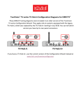
(A) Top-view of SWM Expander
(B) SWM Expander powering
4 SWM units
TECHNICAL SPECIFICATIONS
Parameter
Unit
Value
System Impedance
Ohm
75
Operating IF Frequency Range
MHz
250 - 2150
Input power
dBm
- 10 max
Insertion Loss
dB
<2
Output power
dBm
> - 10
Port to Port Isolation
dB
>35
Return Loss all ports
(Over Frequency Ranges: 250-750
MHz, 950-1450 MHz and 1650 –
2150 MHz)
dB
12
DC Voltage @ the 2 DC Inputs
Volt
29
DC Internal Power Consumption
(max)
Watt
<6
DC Voltage @ the 6 RF Inputs
Volt
0
Environmental Requirements
-
Indoor or Lock Box
Installation
Dimensions
Inches (Wx HxD)
5.8 x 7.1 x 3.1

DIRECTV ACTIVE SATELLITE SWM EXPANDER
SWM-EXPANDR-A-R0-09
MOUNTING INSTRUCTIONS
▪ Insert the SWM units in the SWM Expander
▪ Pull the levers to lock the SWM units in place
▪ Connect the satellite trunk cables to the SWM Expander
▪ The DC power outputs of the SWM Expander (PWR SWM1 to
4) should be connected to the individual SWM units (PWR
port) (see figure (B) on other page)
▪ For DC voltage, use 1 power inserter PI29 per 2 SWM units.
Connect the power inserter(s) to the ports DC PWR IN-1 and
DC PWR IN-2
▪ RF ports will not require external termination.
RF outputs are internally “self terminated” with 75 Ohms
when no SWM unit is connected
▪ The SWM Expander is not capable of powering any
additional device
▪ The SWM Expander can not be used as a polarity locker
▪ The SWM Expander is suited for indoor installation only.
Outdoor installation only advised in combination with an
approved outdoor lock box
/