Page is loading ...

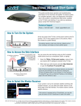
TracVision® HD11
Installation Guide

1
KVH, TracVision, and the unique light-colored dome with dark contrasting baseplate are registered trademarks of KVH Industries, Inc.
All other trademarks are property of their respective companies. The information in this document is subject to change without notice.
No company shall be liable for errors contained herein. Protected by U.S. patents #8,497,810, #8,723,747, and #9,281,561 B2;
additional patents pending. ©2013-2018 KVH Industries, Inc., All rights reserved. 54-0762 Rev. H
These instructions explain how to install the TracVision HD11 satellite TV antenna system on a
vessel. Complete instructions on how to use the system are provided in the User’s Guide.
Installation Steps
Who Should Install the System?
To ensure a safe and effective installation, KVH requires that a KVH-certified marine technician
install the TracVision antenna. KVH-certified technicians have the tools and electronics
expertise necessary to install the system. To find a technician near you, visit www.kvh.com/
wheretogetservice.
Technical Support
If you need technical assistance, please contact KVH Technical Support:
1. Inspect & Record Parts Information ... 3
2. Gather Tools ........................................... 4
3. Plan the Antenna Installation .............. 5
4. Plan the Belowdecks Installation ........ 8
5. Prepare the Antenna Site.................... 14
6. Prepare/Route Cables ........................ 15
7. Rig/Hoist the Antenna(s)................... 16
8. Wire the Antenna(s) ............................ 17
9. Mount the Antenna(s)......................... 18
10. Mount Belowdecks Equipment ......... 20
11. Wire Belowdecks Equipment............. 22
12. Connect to An Onboard Network..... 26
13. Access the Web Interface.................... 28
14. Turn Off Search Modes....................... 30
15. Educate the Customer......................... 32
Europe, Middle East, Africa, Asia
Phone: +45 45 160 180
Email: [email protected]
(Mon.-Fri., 8 am-4:30 pm, +1 GMT)
North/South America, Australia, New Zealand
Phone: +1 401 847-3327
Email: [email protected]
(Mon.-Fri., 9 am-6 pm ET, -5 GMT)
(Sat., 9 am-2 pm ET, -5 GMT)
TracVision® HD11 Installation Guide

3
Before you begin, follow these steps to make sure
you have everything you need to complete the
installation.
a. Unpack the box and ensure it contains
everything shown in Figure 1 and on the
Kitpack Contents Lists.
NOTE: A SmartSwitch Service/System Selector is
required for dual-antenna installations, while it is
optional for single-antenna installations. It is referred
to as the “SmartSwitch” throughout this manual.
TIP: If possible, save the crate and packaging for
future use in case you need to ship the system later.
b. Carefully examine all of the supplied parts to
ensure nothing was damaged in shipment.
c. Record the system serial numbers in the
Installation Worksheet (supplied in the
Customer Welcome Kit) (see Figure 2). Refer
to the Installation Worksheet for serial
number locations.
Keep the Installation Worksheet handy to
help you plan the installation and record
important information needed later for
system setup. To enable activation of the
TracVision HD11’s GPRS modem, you will
need to send the completed worksheet to
KVH.
IMPORTANT!
Inspect & Record Parts Information
1
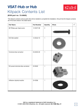
Figure 1 Primary Components
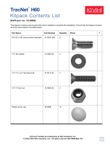
Figure 2 Installation Worksheet
Radome
Antenna
Baseplate
Service
Hatch (x2)
Antenna Control Unit (ACU)
CONTROL UNIT MENU CHANGE ACCEPT EXIT
ANTENNA
POWER
®
TRACKING SATS
DIRECTV 99/101/103
SmartSwitch Service/System Selector (if equipped)
MULTISWITCH OUT ANTENNA INPUT
POWER PORT/A
321 STBD/B
®
TracVision® HD11 Installation Worksheet
Page 1 of 7
54-0829 Rev. A
IMPORTANT! Completed Worksheets Must be Sent to KVH for GPRS Modem Activation!
Complete each page of this installation worksheet to plan and record important information you will need for system
setup. To activate the system’s GPRS modem, send the completed worksheet to KVH. Refer to the TracVision HD11
Installation Guide for complete installation instructions.
Installer, Vessel, and Owner Information
Vessel Information
Date Installed
Vessel Name
Vessel IMO
Installer and Dealer/Ship Builder
State/Province
Address2
Country
Phone
E-mail
Address1
Company Name
Technician Name
E-mail: [email protected] Fax: +1 401 845-8152
Please send completed forms to KVH
Installer’s Notes
Owner Information (if known)
State/Province
Address2
Country
Phone
E-mail
Address1
Owner Name

4
Gather all of the following tools and materials.
You will need these tools to complete the
installation.
•Adhesive tape
• Eye protection
•Pencil
•Scriber
• Light hammer
• Center punch
• 3.75" (95 mm) hole saw
• Electric drill
• 5/8" (16 mm) drill bit
• File
•75RG-6 and/or RG-11 RF coax cables
and F-connector installation tools (see
“Cable Requirements” on page 11)
• Snap-N-Seal® F-connectors (or
equivalent)
• Silicone sealant (or equivalent)
•Heat shrink gun
• Wire strippers
• Wire crimpers
• #1 Phillips screwdriver
• 5/32" hex key
• 7/16" open-end torque wrench set to
20 in-lbs (2.25 N-m) of torque
• 7/16" socket/ratchet or nut driver
• 1/2" open-end wrench
• 3/4" socket/ratchet or wrench
• 3/4" socket/torque ratchet capable of
settings between 35 and 40 ft-lbs (47 and 54
N-m) of torque
• Voltmeter
• Isolation transformer, if required (see “AC
Power Requirements” on page 12)
• PC or mobile device (preferably with
Internet access)
•X-ACTO
® knife
• Needle-nose cutting pliers
• Ruler or tape measure
• NMEA interface cable (for heading input)
Gather Tools
2

5
Select the antenna mounting site(s) based on the
guidelines within this section. Guidelines are
organized into the following categories:
• Mounting Surface
• Power/Data Cable Length
•Blockage
• Pedestal Structure Requirements
• Antenna Orientation
• Radar/High-Power Radio Transmitters
Mounting Surface
• If available, install the antenna on a platform
or pedestal, rather than on a deck. Both
service hatches should be fully accessible for
installation and service.
• Make sure the mounting surface is wide
enough to accommodate the antenna’s base
(see Figure 3). Also make sure it is flat, level
(within ±1°), strong enough to support the
antenna’s weight (200 lbs (90 kg)), and rigid
enough to withstand vibration.
• Choose a mounting surface as close as
possible to the intersection of the vessel’s
centerline and midships.
Power/Data Cable Length
If you wish to use the supplied power/data
cable, the antenna must be mounted within 100 ft
(30 m) of its ACU. However, you can order a
longer cable if needed – contact KVH for details.
Plan the Antenna Installation
Figure 3 Antenna Dimensions
13V/22KHz
18V/22KHz
Power/D ata
13V
18V
57.28"
(145.50 cm)
19.01"
(48.29 cm)
ø51.315"
(130.34 cm)
9.744"
(24.75 cm)
9.744"
(24.75 cm)
Mounting Hole
4x ø.63" (1.60 cm)
ø13.780"
(35.00 cm)
Cable Connectors
(cable cover not shown)
Service
Hatch
Service
Hatch
Side View
Bottom View
Cable
Connectors
3

6
Pedestal Structure Requirements
If a pedestal is going to be used, it must meet the
following minimum requirements. Refer to
Figure 3.
NOTE: If the pedestal exceeds 3.28 ft (1 m), braces
must be placed at 120° intervals. Sizing is based on
Structural Steel Tubing 60,000 psi (415 MPa)
minimum yield.
Pedestal
Height
(A)
3.28 ft
1 m
6.56 ft
2 m
9.84 ft
3 m
Tube OD
(B)
9.0"
230 mm
8.0"
203.2 mm
10"
254 mm
Tube
Wall
Thickness
(C)
0.5"
12.7 mm
0.5"
12.7 mm
0.5"
12.7 mm
Brace
Height
(D)
N/A 5.56 ft
1.7 m
7.34 ft
2.24 m
Brace OD
(E)
N/A 3.0"
76.2 mm
6.0"
152.4 mm
Brace
Thickness
(F)
N/A 0.25"
6.35 mm
0.5"
12.7 mm
Brace
Angle
(G)
N/A 30°25°
Continued Plan the Antenna Installation
3
Figure 4 Pedestal and Brace Dimensions
E
F
Brace
Pedestal
B
C
120°
AD G

7
Blockage
The antenna requires a clear view of the sky to
track satellites. Be sure to choose a location that
does not block the antenna’s -24° to +119°
elevation range (see Figure 5).
Antenna Orientation
• You may mount the antenna so that the front
of the antenna (opposite the cable connectors)
is facing the vessel’s bow, stern, port, or
starboard (see Figure 6).
• If you are installing two TracVision HD11
antennas, mount the antennas facing in
opposite directions (180° offset).
Radar/High-Power Radio Transmitters
Many variables determine the exact minimum
distance required between the antenna and
radar/high-power radio transmitters, including
transmitter beam properties and the reflective
properties of nearby surfaces. However, consider
the following general guidelines when selecting a
safe antenna location:
• Mount the antenna as far away as possible
from the radar and high-power radio
transmitters.
• Do not mount the antenna at the same level
as the radar. Most radar transmitters emit RF
energy within an elevation range of -15° to
+15° (see Figure 7). Most RF energy can be
avoided by mounting the antenna outside
this elevation range – as long as the antenna
is at least 10 ft (3 m) away from the
transmitter. For best results, KVH
recommends maintaining as much vertical
separation as possible between the antenna
and any radar/high-power radio transmitter.
RF emission from radars and high-power
radio transmitters might damage the antenna
or impair system performance. Be sure to
consider the following guidelines when
selecting an antenna location.
IMPORTANT!
Continued Plan the Antenna Installation
Figure 5 Antenna Blockage
Figure 6 Antenna Forward
Figure 7 Radar/High-Power Radio Transmitter Interference
Blocked!
Antenna
Vessel Platform
-24° to +119°
Look Angle
Mast
Antenna - Top View
Hatch
Hatch
Cable Connectors
(Antenna Rear)
FWD Arrow Inside
Radome (Face
Vessel’s Bow, Stern,
Port, or Starboard)
Antenna
Antenna
+15°
-15°
Potential Radar
Interference
10 ft (3 m)
Minimum
Radar
3

8
Plan the installation of the belowdecks
equipment by using the Installation Worksheet
(supplied in the Welcome Kit) and following the
requirements in this section:
• Multiswitch Requirements
• Installation Location Requirements
• Mounting Options
• SmartSwitch Requirements (if equipped)
• Cable Requirements
•AC Power Requirements
•Grounding Requirements
Multiswitch Requirements
Using the Installation Worksheet, plan and
record multiswitch requirements based on the
number of tuners needed. Refer to the
Installation Worksheet for details.
Installation Location Requirements
• Choose belowdecks installation locations that
are dry, well-ventilated, and away from any
heat sources or salt spray.
• In order to use the supplied power/data
cable, the antenna must be mounted within
100 ft (30 m) of its ACU. However, you can
order a longer cable if needed – contact KVH
for details.
• If you are installing a SmartSwitch and you
wish to use the supplied PC data cable,
ACU A must be installed within 3 feet (1 m)
of the SmartSwitch. However, longer cabling
may be used to a maximum of 25 feet (7.6 m)
– contact KVH for details.
Plan the Belowdecks Installation
Figure 8 ACU Dimensions
CONTROL UNIT
ANTENNA
POWER
MENUS CHANGE ACCEPT EXIT
Side View
Front View
19.00"
(48.26 cm)
16.75"
(42.55 cm)
2.63"
(6.68 cm)
18.31"
(46.51 cm)
1.75"
(4.45 cm)
0.44"
(1.12 cm)
4 x
11.18"
(28.40 cm)
16.31"
(41.43 cm)
Strain Relief Bracket
ø.
25"
(0.64 cm)
Top View
4

9
• Using the Installation Worksheet, plan and
record the installation locations of the
multiswitches, ACU(s), and SmartSwitch (if
equipped). Refer to the Installation
Worksheet for details.
NOTE: ACU dimensions are shown in Figure 8 on
page 8. For SmartSwitch dimensions, see Figure 9.
Continued Plan the Belowdecks Installation
Figure 9 SmartSwitch Dimensions
19.00"
(48.26 cm)
16.75"
(42.55 cm)
2.63"
(6.68 cm)
18.31"
(46.51 cm)
1.75"
(4.45 cm)
0.44"
(1.12 cm)
11.18"
(28.40 cm)
16.31"
(41.43 cm)
Side View
Front View
4 x
ø.
25"
(0.64 cm)
Top View
Strain Relief Bracket
4

10
Mounting Options
Select a mounting option for the ACU(s) and the
SmartSwitch (if equipped).
You can mount the ACU(s) and the SmartSwitch
in a standard 19" (48.26 cm) equipment rack,
together or separately (see Figure 10). The ACU
and SmartSwitch are 1.5U in height each.
Alternatively, you can mount the equipment to a
horizontal surface; the L-shaped mounting
brackets can attach to either the top or bottom of
the ACU(s) and SmartSwitch (see Figure 10).
SmartSwitch Requirements (if equipped)
Using the Installation Worksheet, plan and
record important information for each receiver/
DVR group. Refer to the Installation Worksheet
for details.
Wireless Router Requirements (optional)
Select a mounting location in a dry, well-
ventilated area belowdecks away from any heat
sources or salt spray. Also be sure the location
provides adequate Wi-Fi reception. Do not install
it in an area surrounded by metal or near any
electrical devices that emit RF noise.
Continued Plan the Belowdecks Installation
Figure 10 ACU/SmartSwitch Mounting Options
MULTISWITCH OUT ANTENNA INPUT
POWER PORT/A
321 STBD/B
®
CONTROL UNIT MENU CHANGE ACCEPT EXIT
ANTENNA
POWER
®
TRACKING SATS
DIRECTV 99/101/103
CONTROL UNIT MENU CHANGE ACCEPT EXIT
ANTENNA
POWER
®
TRACKING SATS
DIRECTV 99/101/103
CONTROL UNIT MENU CHANGE ACCEPT EXIT
ANTENNA
POWER
®
TRACKING SATS
DIRECTV 99/101/103
MULTISWITCH OUT ANTENNA INPUT
POWER PORT/A
321 STBD/B
®
ACU/SmartSwitch Joint Rack Mount
SmartSwitch Rack Mount
ACU Rack Mount
ACU Horizontal Surface Mount
Rack Mounting
Bracket (x2)
Rack Mounting
Bracket (x2)
Joint Rack
Mounting Bracket (x2)
Horizontal Surface
Mounting Bracket (x2)
1.5U
1.5U
3U
MULTISWITCH OUT ANTENNA INPUT
POWER PORT/A
321 STBD/B
®
SmartSwitch Horizontal Surface Mount
Horizontal Surface
Mounting Bracket (x2)
4

11
Cable Requirements
a. Using the Installation Worksheet, plan and
record the type, quantity, and approximate
lengths of the cables required.
b. Ensure you have the appropriate connector
installation tool and cable connectors needed
to complete the installation (see Figure 11).
• RF cables must be rated for 75not
• Low-quality, poorly terminated, or
improperly installed RF cables are the
most common cause of system problems.
Terminate all RF cables with high-quality
“F” connectors using the proper
stripping/crimping tools, exactly to the
manufacturer’s specifications.
• When determining cable lengths, be sure
to account for an adequate service loop,
approximately 8" (20 cm) at both ends of
each cable.
IMPORTANT!
Continued Plan the Belowdecks Installation
Figure 11 Cable Types, Connectors, and Tools
Up to 100 ft (30 m) Cable Run
Cable RG-6
(KVH part #32-0417-100)
Connector Belden SNS1P6
(KVH part #23-0170)
Tools Augat IT1000
(KVH part #19-0242)
Strip
Lengths
Up to 200 ft (60 m) Cable Run
Cable RG-11
(KVH part #32-1272-200)
Connector Belden SNS11AS
(KVH part #23-0213)
Tools Belden CST596711,
L3011B (KVH part #72-0493)
Strip
Lengths
0.25" (6.35 mm)
0.5" (12.7 mm)
0.04" (1.02 mm) dia.
0.25" (6.35 mm)
0.5" (12.7 mm)
0.064" (1.63 mm) dia.
4

12
AC Power Requirements
The TracVision system is designed to run on
3-wire single-phase AC power (hot, neutral, and
ground). Voltage between hot-neutral and hot-
ground should each measure between 100-
240 VAC.
Many large ships use two-phase, split-phase, or
delta power instead (3 wires: hot, hot, and
ground; no neutral). In this case, voltage between
hot-hot measures the proper voltage (100-
240 VAC); while hot-ground measures only half
the voltage (50-120 VAC). Although the
TracVision system can operate on this type of
power, the excess voltage present on the second
phase will cause a small amount of current to
leak onto ship's ground. This leakage current
might be unacceptable on some vessels, so check
with the customer or ship's electrician and get
permission before you run the system on two-
phase power. Also be sure to ground the system,
as explained in “Grounding Requirements” on
page 13.
If two-phase power is the only available power
source onboard, and if leakage current is
unacceptable, KVH recommends that you install
a suitable isolation transformer to supply single-
phase power to the antenna system and run a
ground wire from the transformer to ship's
ground. In addition, since ground fault
protection devices cannot detect faults behind a
transformer, you will also need to install a
ground fault monitoring device between the
isolation transformer and the antenna system if
ground fault protection is required on the vessel.
Continued Plan the Belowdecks Installation
Figure 12 Power Requirements
TracVision Equipment
Ground
Neutral
N
100-240 VAC
Isolation Transformer
50-120 VAC
50-120 VAC
Ground
Shipboard
Two-Phase,
Split-Phase,
or Delta Power
Single-Phase
Power Input
Ground Fault
Monitor
(when required)
Not Used
TracVision Equipment
Ground
50-120 VAC
Shipboard
Two-Phase,
Split-Phase,
or Delta Power
50-120 VAC
Leakage Current
TracVision Equipment
Shipboard
3-Wire
Single-Phase
AC Power
Ground
Neutral
N
100-240 VAC
OR
OR
4

13
Grounding Requirements
Proper grounding of the TracVision system to
ship's ground is critically important, as it protects
the equipment from lightning and electrostatic
discharges (ESD). Failure to ground the chassis of
the ACU risks damage to the antenna and electric
shock.
In a standard installation with a connection to
single-phase AC power, the antenna system is
normally connected to ship's ground through the
ground wire of the ACU's power plug. As an
alternative, you may run a separate ground wire
from the TracVision equipment's chassis to ship's
ground, or mount the equipment within a
grounded equipment rack.
WARNING
Failure to ground the TracVision system
properly to ship's ground will cause an
unsafe floating ground condition, risking
damage to the antenna and electric shock,
potentially resulting in DEATH. In a
floating ground condition, the difference
between the equipment's chassis ground and
the ship's ground can measure well over
100 volts, when it normally should not
exceed 25 volts. Therefore, always measure
the difference in potential between chassis
ground and ship's ground to make certain
that there is no dangerous floating ground
condition, even if the ground pin of the
vessel's AC power plug appears to be intact.
Continued Plan the Belowdecks Installation
4

14
Follow the steps below to prepare the antenna
mounting site(s).
a. Unfold the antenna mounting template
(supplied in the Customer Welcome Kit) and
place it onto the mounting surface.
b. Orient the mounting template so that the
“FWD” (forward) arrow on the template
points toward the vessel’s bow and is parallel
to the vessel’s centerline (see Figure 13).
c. Secure the mounting template in place using
adhesive tape, or equivalent.
d. Using a light hammer and center punch,
mark the cable access hole and mounting
holes on the mounting surface in the
locations indicated on the template.
e. Using an electric drill with a 5/8" (16 mm) bit,
drill the four antenna mounting holes at the
locations you marked in the previous step.
f. Cut out the 3.75" (95 mm) cable access hole at
the location you marked earlier.
g. Using a file, smooth the edges of the cable
access hole to protect the cables. Later, you
will route the power/data and RF cables
through this hole and into the vessel.
h. Clean and dry the mounting surface.
i. Peel off the paper backing from one of the
supplied foam seals to expose the adhesive.
Then press the foam seal down firmly onto
the mounting surface, ensuring the hole in
the foam seal aligns with the cable access hole
in the mounting surface (see Figure 13).
j. If you are installing two antennas, repeat the
steps above to prepare the second antenna
mounting site.
Prepare the Antenna Site
Figure 13 Mounting Holes/Cable Access Hole/Foam Seal
Good Bolt
Pattern
Poor Bolt
Pattern
Ø.63" (Ø16 mm)
Antenna Mounting
Hole (x4)
Ø3.75" (Ø95 mm)
Cable Access Hole
9.744"
(247.50 mm)
9.744"
(247.50 mm)
Face Vessel Bow
FWD
Foam Seal
5

15
Follow the steps below to prepare and route
cables from the antenna mounting site(s) to the
belowdecks equipment locations.
a. Apply the “Antenna A” cable labels
(supplied in the antenna kitpack) to both
ends of the appropriate cables at the antenna
mounting site (Antenna A) (see Figure 14 and
Figure 15).
b. Route the cables through the cable access hole
to the belowdecks equipment location(s) you
determined earlier.
c. If you are installing two antennas, repeat the
steps above to prepare the cables at the
second antenna’s mounting site (Antenna B)
(see Figure 16).
• Be sure to maintain the appropriate
minimum cable bend radius to ensure
cable integrity. RG-6 cables require a bend
radius of at least 3" (7.6 cm). RG-11 cables
require a bend radius of at least 4.5"
(11.5 cm).
• Be sure to leave an adequate service loop,
approximately 8" (20 cm) at both ends of
each cable.
IMPORTANT!
Prepare/Route Cables
6
Figure 14 Cable Labels
Figure 15 Antenna A Cable Labels/Routing
Figure 16 Antenna B Cable Labels/Routing (if equipped)
Label
Text
Label
Text
Label
Text
Label
Text
Label
Text
Label
Text
Label
Text
Label
Text
Label
Text
Label
Text
Label
Text
Label
Text
Label
Text
Label
Text
Label
Text
Label
Text
Label
Text
Label
Text
Label
Text
Label
Text
Label
Text
Label
Label
Label
Label
Label
Foam Seal
Antenna A
13V
Antenna A
Power/Data
Antenna A
18V
Antenna A
18V/22KHz
Antenna A
13V/22KHz
Label
Label
Label
Label
Label
Foam Seal
Antenna B
13V
Antenna B
Power/Data
Antenna B
18V
Antenna B
18V/22KHz
Antenna B
13V/22KHz

16
Follow the steps below to remove the shipping
bolts securing the antenna to the pallet and safely
rig each antenna for crane hoisting.
NOTE: If you are installing two antennas, verify
antenna serial numbers prior to hoisting to ensure the
antennas are moved to their correct mounting
locations.
a. Using a 7/16" socket/ratchet or nut driver,
unlock the three hex latches securing each of
the antenna’s service hatches (see Figure 17).
Then gently lower the hatches. Now you can
access the four shipping bolts securing the
antenna’s baseplate to the pallet.
b. Using a 3/4" socket/ratchet or wrench,
remove the four 1/2"-13 bolts securing the
antenna to the pallet. Then set the bolts aside.
TIP: You will use the new mounting bolts supplied in
the kitpack when mounting the antenna later.
However, you might wish to keep these bolts in case
you need to ship the antenna later.
c. Reinstall both antenna service hatches. Secure
each service hatch using the three hex latches.
d. Secure crane rigging appropriate for lifting
the 200-lb (90 kg) antenna to each of the
antenna’s four lift brackets (see Figure 19).
e. If you are installing two antennas, repeat
these steps to rig and hoist the second
antenna.
The antenna’s radome and baseplate have
painted surfaces. Be sure to take protective
measures to avoid gouging or scratching the
antenna during the rigging operation.
IMPORTANT!
Rig/Hoist the Antenna(s)
Figure 17 Service Hatch/Hardware
Figure 18 Shipping Bolts (Antenna Bottom View)
Figure 19 Antenna Crane Rigging (example)
Service
Hatch (x2)
1/4-turn Hex
Latch (x6)
1/2"-13
Bolt (x4)
Lift
Bracket (x4)
Rope to Prevent
Antenna from
Tipping
Rope
Antenna’s
Center of Gravity
7

17
Follow the steps below to wire the antenna(s)
and attach the antenna’s foam seal.
a. Clean and dry the bottom of the antenna
baseplate (see Figure 20).
b. Peel off the paper backing from one of the
supplied foam seals to expose the adhesive.
Align the foam seal so it is centered on the
antenna (see Figure 20). Then press the foam
seal firmly onto the underside of the antenna.
c. Connect the power/data cable to the
antenna’s power/data connector (see
Figure 21). Hand-tighten until the connector
locks in place; do not use excessive force.
d. Connect the power/data cable’s ground strap
to the ground point on the antenna’s
connector plate (see Figure 21). Be sure to
secure the ground strap’s ring terminal
between the star washer and the nut.
e. Fill half of the inner body of the “18V,””13V,”
“18V/22KHz,” and “13V/22KHz” cables’
connectors with the supplied silicone grease
to prevent moisture and corrosion (see
Figure 21).
f. Connect and slowly hand-tighten the RF
cables to the corresponding antenna
connectors, allowing the grease to diffuse and
settle into the entire space within the
connector (see Figure 21).
g. Using a 7/16" open-end torque wrench set to
20 in-lbs (2.25 N-m), tighten each of the RF
cable connections.
h. Using silicone sealant (or equivalent), create a
weather-tight seal over each antenna
connection.
i. Using a #1 Phillips screwdriver, install the
cable cover (supplied in the kitpack) onto the
antenna and secure in place with the six #6-32
captive screws and washers (see Figure 22).
j. If you are installing two antennas, repeat
these steps to wire the second antenna.
Refer to the cable and connector labels to
ensure the antenna is wired exactly as shown
in Figure 21.
IMPORTANT!
Wire the Antenna(s)
Figure 20 Foam Seal
Figure 21 Cable Connections
Figure 22 Cable Cover/Screws/Washers
Foam Seal
Antenna Baseplate (Bottom View)
13V/22KHz
18V/22KHz
Powe r/Da ta
13V
18V
Foam Seals
Mounting
Surface
Baseplate
Power/
Data
18V/
22KHz
13V/
22KHz
18V 13V
Ground
Strap
13V/22KHz
18V/22KHz
Power/Data
13V
18V
Label
Label
Label
Label
Label
#6-32 Captive Screw
and Washer (x6)
Cable
Cover
8

18
Follow the steps below to mount the antenna to
the mounting surface.
a. Using a 7/16" socket/ratchet or nut driver,
unlock the three hex latches securing each of
the antenna’s service hatches (see Figure 17
on page 16). Then gently lower the hatches.
b. Orient the antenna so the antenna forward
arrow is facing the bow, stern, port, or
starboard (see Figure 23).
c. Using the Installation Worksheet, record the
antenna’s mounting orientation.
NOTE: If you are installing two antennas, mount the
antennas facing opposite directions (180° offset).
d. Carefully lower the antenna using the foam
seals and mounting holes as guides. While
lowering the antenna, adjust the cables as
necessary to maintain an adequate service
loop, approximately 8" (20 cm) of slack.
e. Guide the antenna downward and ensure the
mounting holes and foam seals are aligned.
f. Apply a thin layer of anti-seize lubricant to
the threads of the four supplied 1/2"-13
mounting bolts to prevent galling.
WARNING
Observe the safety warnings printed on the
supplied tube of Loctite® anti-seize lubricant:
“Contains mineral oil, calcium hydroxide,
and copper. May cause skin, eye, and
respiratory irritation. Wear eye protection
and gloves. First aid: In case of eye or skin
contact, flush with water. Obtain medical
attention for any eye or internal contact.”
To prevent damage to the foam seal, do not
reposition the antenna laterally once the
antenna’s foam seal has made contact. If you
need to reposition the antenna, lift the
antenna vertically first.
IMPORTANT!
Mount the Antenna(s)
Figure 23 Antenna Forward
Antenna - Top View
Hatch
Hatch
Cable Connectors
(Antenna Rear)
FWD Arrow Inside
Radome (Face
Vessel’s Bow, Stern,
Port, or Starboard)
9

19
g. At each of the four antenna mounting holes,
place a 1/2" flat washer on a 1/2"-13 bolt and
insert the bolt into the hole from above (see
Figure 24).
h. Secure each mounting bolt to the mounting
surface using a 1/2" flat washer and a 1/2"-13
lock nut from below (see Figure 24).
i. Tighten the mounting bolts in a cross pattern
until the four rubber feet on the baseplate are
bottomed against the mounting surface. KVH
recommends that you tighten the nuts to
between 35 and 40 ft-lbs (47 and 54 N-m) of
torque.
j. Disconnect the crane rigging.
k. Using a 5/32" hex key and 1/2" open-end
wrench, remove the eight screws, flat
washers, and lock nuts securing the four lift
brackets to the antenna (see Figure 25).
Remove the brackets and hardware and set
them aside in a safe place.
TIP: Be sure to save the brackets and bracket hardware
in case you need to relocate the antenna later.
l. Install eight 1/4"-20 screws and washers
(supplied in the kitpack) in place of the
longer mounting bracket screws you
removed in the previous step.
m. Reinstall both antenna service hatches. Secure
each service hatch using the three hex latches.
n. If you are installing two antennas, repeat
these steps to mount the second antenna.
Continued Mount the Antenna(s)
Figure 24 Mounting the Antenna (Side View)
Figure 25 Lift Bracket Removal
Figure 26 Radome Hardware
1/2"-13 Bolt (x4)
1/2" Flat
Washer (x4)
Rubber
Foot (x4)
Mounting
Surface 1/2" Flat
Washer (x4)
1/2"-13 Lock
Nut (x4)
Antenna
Baseplate
Isolation
Bushing (x4)
(preinstalled)
IMPORTANT!
Apply anti-seize
to threads
Foam Seals
Stationary
Plate
Lift Bracket
(x4)
1/4"-20 x 1.5"
Screw (x8)
Counter-sunk
Washer (x8)
1/4"-20 Flat
Washer (x8)
1/4"-20 Lock
Nut (x8)
1/4"-20 x 7/8"
Screw (x8)
Counter-sunk
Washer (x8)
9

20
Follow the steps below to mount the ACU(s) and
SmartSwitch (if equipped).
ACU Rack Mounting
a. Attach the strain-relief bracket to the ACU, as
shown in Figure 27. Using a #1 Phillips
screwdriver, secure the bracket in place using
four #6-32 screws and #6 washers (supplied
in the kitpack).
b. Secure the ACU to the rack using four M6
screws and washers (see Figure 28).
ACU Horizontal Mounting
a. Using a #1 Phillips screwdriver, remove the
six #6-32 screws securing the rack mounting
brackets to the ACU (see Figure 29).
b. Using a #1 Phillips screwdriver, attach the
two horizontal mounting brackets to the sides
of the ACU using four supplied #6-32 screws
and #6 washers (see Figure 30). You can
attach the brackets to either the top or bottom
of the ACU, depending on your desired
mounting location.
c. If you are mounting the ACU to the
underside of a shelf, attach the strain-relief
bracket to the ACU, as shown in Figure 27.
Using a #1 Phillips screwdriver, secure the
bracket in place using four #6-32 screws and
#6 washers (supplied in the kitpack).
NOTE: The ACU does not require a strain-relief
bracket when mounted to the top of a horizontal
surface.
d. Using fasteners appropriate for the mounting
surface, secure the ACU to the mounting
surface using the four mounting bracket
holes.
Mount Belowdecks Equipment
Figure 27 ACU Strain Relief Bracket
Figure 28 ACU Rack Mounting
Figure 29 ACU Rack Mounting Bracket Removal
Figure 30 Horizontal Mounting Brackets
Strain-Relief
Bracket
#6-32
Screw (x4)
#6 Washer
(x4)
CONTROL UNIT MENU CHANGE ACCEPT EXIT
ANTENNA
POWER
®
TRACKING SATS
DIRECTV 99/101/103
Mounting
Hole (x4)
M6 Screw
and Washer (x4)
Rack Mounting
Bracket (x2)
#6-32 Screw (x6)
Horizontal
Mounting
Bracket (x2) #6-32 Screw and
#6 Washer (x4)
10
/