Page is loading ...

1
KVH, TracVision, and the unique light-colored dome with dark contrasting baseplate are registered trademarks of KVH Industries, Inc.
All other trademarks are property of their respective companies. The information in this document is subject to change without notice.
No company shall be liable for errors contained herein. ©2012-2017 KVH Industries, Inc., All rights reserved. 54-0816 Rev.D
These instructions explain how to install a SmartSwitch Service/System Selector (SmartSwitch)
to upgrade a TracVision HD11 system or replace a previously installed SmartSwitch.
Installation Steps
Who Should Install the System?
To ensure a safe and effective installation, KVH requires that a KVH-certified marine technician
install the SmartSwitch. KVH-certified technicians have the tools and electronics expertise
necessary to install the system. To find a technician near you, visit www.kvh.com/
wheretogetservice.
Technical Support
If you need technical assistance, please contact KVH Technical Support:
1. Inspect Parts and Gather Tools............................ 3
2. Plan the Installation............................................... 4
3. Mount the SmartSwitch........................................ 5
4. Wire the SmartSwitch ........................................... 7
5. Launch the Setup Wizard (Upgrades Only)...... 8
6. Turn Off Search Modes (Upgrades Only)........ 10
Europe, Middle East, Asia-Pacific, Africa:
Phone: +45 45 160 180
Email: [email protected]
North/South America, Australasia:
Phone: +1 401 847-3327
Email: [email protected]
For instructions on installing the SmartSwitch and one or two TracVision HD11 systems
together, refer to the TracVision HD11 Installation Guide. For SmartSwitch operation
instructions, refer to the TracVision HD11 User’s Guide.
IMPORTANT!
SmartSwitch Upgrade/Replacement Instructions

3
Before you begin, follow these steps to make sure
you have everything you need to complete the
installation.
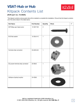
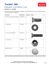
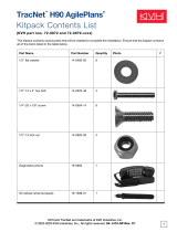
a. Unpack the box and ensure it contains
everything shown on the Kitpack Contents
List.
b. Carefully examine all of the supplied parts to
ensure nothing was damaged in shipment.
c. Gather the following tools. You will need
these tools to complete the installation.
• #1 Phillips screwdriver
• PC (preferably with Internet access)
•7/16" wrench
Some SmartSwitch connectors include
connector terminators. Only remove
terminators from connectors you will be
wiring to (see “Wiring Diagrams” on
page 12).
IMPORTANT!
Inspect Parts and Gather Tools
1
Figure 1 SmartSwitch
Figure 2 SmartSwitch Dimensions
MULTISWITCH OUT ANTENNA INPUT
POWER PORT/A
321 STBD/B
®
19.00"
(48.26 cm)
16.75"
(42.55 cm)
2.63"
(6.68 cm)
18.31"
(46.51 cm)
1.75"
(4.45 cm)
0.44"
(1.12 cm)
11.18"
(28.40 cm)
16.31"
(41.43 cm)
Side View
Front View
4 x
ø.
25"
(0.64 cm)
Top View
Strain Relief Bracket

4
Follow the steps below to plan the SmartSwitch
installation.
Select an Installation Location
When selecting an installation location, consider
the following:
• Choose a belowdecks installation location
that is dry, well-ventilated, and away from
any heat sources or salt spray.
• The SmartSwitch must be installed within
3 feet (1 m) of the ACU A (the TracVision
HD11 Antenna Control Unit (ACU)
connected to Antenna A) in order to use the
supplied PC data cable (25 ft (7.6 m)
maximum). However, longer cabling may be
used – contact KVH for details.
Choose a Mounting Option
Select one of the following SmartSwitch
mounting options.
• You can mount the SmartSwitch in a
standard 19" (48.26 cm) equipment rack,
either separately or together with an ACU
(see Figure 3). The SmartSwitch is 1.5U in
height.
• Alternatively, you can mount the
SmartSwitch to a horizontal surface; the
horizontal surface mounting brackets can
attach to either the top or bottom of the
SmartSwitch (see Figure 3).
Plan the Installation
Figure 3 SmartSwitch Mounting Options
MULTISWITCH OUT ANTENNA INPUT
POWER PORT/A
321 STBD/B
®
CONTROL UNIT MENU CHANGE ACCEPT EXIT
ANTENNA
POWER
®
TRACKING SATS
DIRECTV 99/101/103
MULTISWITCH OUT ANTENNA INPUT
POWER PORT/A
321 STBD/B
®
ACU/SmartSwitch Joint Rack Mount
SmartSwitch Rack Mount
Rack Mounting
Bracket (x2)
Joint Rack
Mounting Bracket (x2)
1.5U
3U
MULTISWITCH OUT ANTENNA INPUT
POWER PORT/A
321 STBD/B
®
SmartSwitch Horizontal Surface Mount
Horizontal Surface
Mounting Bracket (x2)
2

5
Follow the steps below to mount the
SmartSwitch using the desired mounting option.
Rack Mounting
a. Attach the strain-relief bracket to the
SmartSwitch, as shown in Figure 4. Using a
#1 Phillips screwdriver, secure the bracket in
place using four #6-32 screws and #6 washers
(supplied in the kitpack).
b. Secure the SmartSwitch to the rack using four
M6 screws and washers (see Figure 5).
Horizontal Mounting
a. Using a #1 Phillips screwdriver, remove the
six screws securing the rack mounting
brackets to the SmartSwitch (see Figure 6).
b. Using a #1 Phillips screwdriver, attach the
two horizontal mounting brackets to the sides
of the SmartSwitch using four supplied
#6-32 screws and #6 washers (see Figure 7).
You can attach the brackets to either the top
or bottom of the SmartSwitch, depending on
your desired mounting location.
c. If you are mounting the SmartSwitch to the
underside of a shelf, attach the strain-relief
bracket, as shown in Figure 4. Using a #1
Phillips screwdriver, secure the bracket in
place using four #6-32 screws and #6 washers
(supplied in the kitpack).
d. Using fasteners appropriate for the mounting
surface, secure the SmartSwitch to the
mounting surface using the four mounting
bracket holes.
Mount the SmartSwitch
Figure 4 Strain-Relief Bracket Mounting
Figure 5 SmartSwitch Rack Mounting
Figure 6 SmartSwitch Rack Mounting Bracket Removal
Figure 7 Horizontal Mounting
Strain-Relief
Bracket
#6-32
Screw (x4)
#6 Washer
(x4)
MULTISWITCH OUT ANTENNA INPUT
POWER PORT/A
321 STBD/B
®
Mounting
Hole (x4)
M6 Screw
and Washer (x4)
Rack Mounting
Bracket (x2)
#6-32 Screw (x6)
Strain-Relief
Bracket
Horizontal
Mounting Bracket (x2)
#6-32
Screw (x6)
#6 Washer
(x6)
3

6
Joint ACU/SmartSwitch Rack Mounting
a. Using a #1 Phillips screwdriver, remove the
six screws securing the rack mounting
brackets to the SmartSwitch (see Figure 6 on
page 5).
b. Repeat Step a. to remove the six screws
securing the rack mounting brackets to the
ACU.
c. Attach the joint rack mounting brackets to the
ACU and SmartSwitch, as shown in Figure 8.
Secure the brackets in place using twelve
#6-32 screws and washers (supplied in the
kitpacks).
d. Attach the strain-relief bracket and retaining
straps, as shown in Figure 8. Secure them in
place using eight #6-32 screws and
#6 washers (supplied in the kitpacks).
NOTE: Only the SmartSwitch strain-relief bracket
must be installed. The ACU does not require a strain-
relief bracket when jointly mounted with the
SmartSwitch.
e. Secure the joint assembly to the rack using
four M6 screws and washers.
Continued Mount the SmartSwitch
Figure 8 ACU/SmartSwitch Joint Assembly
ACU
Retaining
Strap (x2)
Joint Rack
Mounting
Bracket (x2)
Strain-Relief
Bracket
SmartSwitch
#6-32 Screw
(x20)
#6 Washer
(x20)
3

7
Wiring instructions vary according to the
customer’s specific system configuration and
hardware. Refer to the wiring diagrams
provided in Appendix A on page 12 for
complete wiring instructions.
NOTE: When connecting cables, first hand-tighten
the connector, then tighten 1/4 turn using a 7/16"
wrench.
NOTE: Be sure to apply the cable labels (supplied in
the kitpack) to the cables that will connect the
SmartSwitch to other system components.
Wiring SWM and Non-SWM Hardware
Connect your receivers/DVRs according to the
diagram for your particular configuration.
NOTE: Only DIRECTV® programming in North
America supports SWM-compatible receivers and
DVRs. All linear receivers/DVRs and other circular
receivers/DVRs are not SWM-compatible.
SmartSwitch Input Wiring Diagrams
• One TracVision HD11 Antenna/ACU (see
page 12)
• Two TracVision HD11 Antennas/ACUs (see
page 13)
SmartSwitch Output Wiring Diagrams
• Overview (see page 14)
• 32 Non-SWM-compatible Tuners (see
page 15)
• 16 SWM-compatible Tuners and 32 Non-
SWM-compatible Tuners (see page 16)
• 32 SWM-compatible Tuners and 32 Non-
SWM-compatible Tuners (see page 17)
Wire the SmartSwitch
Figure 9 Wiring Overview
Antenna A Antenna B
(If equipped)
18V 18V/22KHZ
MULTISWITCH OUT 1
13V/22KHZ13V 18V 18V/22KHZ
MULTISWITCH OUT 2
13V/22KHZ13V
18V 18V/22KHZ
PORT/A ANTENNA INPUT
13V/22KHZ13V 18V 18V/22KHZ
STARBOARD/B ANTENNA INPUT
13V/22KHZ13V
18V 18V/22KHZ
MULTISWITCH OUT 3
13V/22KHZ13V
TO ACU
SmartSwitch
Receiver/DVR
Group 1
Receiver/DVR
Group 3
Receiver/DVR
Group 2
Fuse 3.15A 250V ~ Fast Acting
Ethernet SmartSwitch
Controller
Maintenance
RS232
To Ant enn a
This device complies with Part 15 of the FCC rules. Operation is subject to the following two conditions:
(1) This device must not cause harmful interference, and (2) This device must accept any
interference received, including interference that may cause undesired operation.
Red (+48V)
Black (Gnd)
White/Gray
Gray/White
White/Orange
Orange/White
White/Brown
Brown/White
White/Blue
Blue/White
White/Green
Green/White
Red/Orange
Orange/Red
Red/Green
Green/Red
B (+)
A (–)
Wire Color/Stripe Color
WiFi
NMEA
Single Phase AC Input 100-240V ~ 200W MAX 50/60 Hz
KVH and TracVision are registered
trademarks of KVH Industries, Inc.
Tested to comply
with FCC Standards
Meets requirements
CAUTION
RISK OF ELECTRIC SHOCK
DO NOT OPEN
ACU A (Master)
Fuse 3.15A 250V ~ Fast Acting
Ethernet SmartSwitch
Controller
Maintenance
RS232
To Ant enn a
This device complies with Part 15 of the FCC rules. Operation is subject to the following two conditions:
(1) This device must not cause harmful interference, and (2) This device must accept any
interference received, including interference that may cause undesired operation.
Red (+48V)
Black (Gnd)
White/Gray
Gray/White
White/Orange
Orange/White
White/Brown
Brown/White
White/Blue
Blue/White
White/Green
Green/White
Red/Orange
Orange/Red
Red/Green
Green/Red
B (+)
A (–)
Wire Color/Stripe Color
WiFi
NMEA
Single Phase AC Input 100-240V ~ 200W MAX 50/60 Hz
KVH and TracVision are registered
trademarks of KVH Industries, Inc.
Tested to comply
with FCC Standards
Meets requirements
CAUTION
RISK OF ELECTRIC SHOCK
DO NOT OPEN
ACU B (Slave)
*IMPORTANT! Both ACUs must be connected to each other via either
a dedicated router or wired through the existing onboard network. If
you do not have a network, install a router or router and switch.
To Network*
To Network*
4

8
If you are upgrading the TracVision HD11
system to include a SmartSwitch, follow the steps
below to launch the Setup Wizard and
reconfigure system settings. If you are replacing
a previously installed SmartSwitch, the
procedure is complete (your system is already
configured).
NOTE: If you have a dual-antenna system, perform
the following steps using the Master ACU.
a. Press the power button on the front of the
ACU to apply power to the TracVision
system (see Figure 11). Then wait up to
5 minutes for system startup.
b. On the front panel of the ACU, navigate to
System Settings > Ethernet Settings and
configure the parameters as follows:
• Set State to “Static.”
• Set the IP Address to an available IP
address outside of your router’s DHCP
range (refer to the router’s user manual for
details).
For example, if the router assigns IP
addresses ranging from 192.168.1.100 to
192.168.1.139, you could set the Master
ACU’s IP address to 192.168.1.150.
• Set the Subnet Mask (Mask) and Gateway
(Gway) parameters, as directed by the
router’s user manual.
If you have a dual-antenna system, before
continuing, decide which ACU will be the
Master and which will be the Slave.
IMPORTANT!
Launch the Setup Wizard (Upgrades Only)
Figure 10 ACU Network Connection Options
Figure 11 ACU Power Button
Fuse 3.15A 250V ~ Fast Acting
Orange/Red
Red/Green
Green/Red
B (+)
A (–)
Wire Color/Stripe Color
WiFi
NMEA
Single Phase AC Input 100-240V ~ 200W MAX 50/60 Hz
KVH and TracVision are registered
trademarks of KVH Industries, Inc.
Tested to comply
with FCC Standards
Meets requirements
CAUTION
RISK OF ELECTRIC SHOCK
DO NOT OPEN
Ethernet SmartSwitch
Controller
Maintenance
RS232
To Antenna
This device complies with Part 15 of the FCC rules. Operation is subject to the following two conditions:
(1) This device must not cause harmful interference, and (2) This device must accept any
interference received, including interference that may cause undesired operation.
Red (+48V)
Black (Gnd)
White/Gray
Gray/White
White/Orange
Orange/White
White/Brown
Brown/White
White/Blue
Blue/White
White/Green
Green/White
Red/Orange
ETHERNET
Wi-Fi
Antenna
CONTROL UNIT MENU CHANGE ACCEPT EXIT
ANTENNA
POWER
®
TRACKING SATS
DIRECTV 99/101/103
Power
Button
5

9
c. If you have a single-antenna system, skip to
step d.
If you have a dual-antenna system, repeat
steps a-b for the Slave ACU, setting the Slave
ACU’s IP address to another number outside
of your router’s DHCP range.
For example, if you set the Master ACU’s IP
address to 192.168.1.150, you could set the
Slave ACU’s IP address to 192.168.1.151.
NOTE: If you are going to use a wireless network
connection to access the web interface, ensure you
have applied security settings, such as encryption, to
protect the network from outside intrusion. If the
network is not secure, outsiders within range of the
wireless network might use the wireless connection
without your knowledge.
d. Open the web browser on a PC connected to
the same network. Then type the ACU’s IP
address (set in step b) into the browser’s
address bar.
For example, if the ACU’s IP address was set
to 192.168.1.150, you would enter the
following into the browser’s address bar:
http://192.168.1.150
NOTE: Alternatively, you can connect directly to the
ACU’s Ethernet port with a laptop PC configured for
DHCP. Then open the web browser and enter
http://169.254.253.1 to access the web interface.
e. Log into the web interface.
The default login credentials are:
Username: admin
Password: password
f. Select Settings > General Settings. Then select
the Launch button to launch the Setup
Wizard (see Figure 12).
g. Follow the Setup Wizard’s onscreen
instructions to reconfigure system settings
(see Figure 13).
Continued Launch the Setup Wizard
5
Figure 12 Launch Setup Wizard Button
Figure 13 Setup Wizard

10
If you are upgrading a TracVision HD11 dual-
antenna system to include a SmartSwitch, follow
the steps below to turn off Search Modes 1 and 2
on each antenna. If you are replacing a
previously installed dual-antenna system
SmartSwitch, the procedure is complete (the
search modes have already been turned off).
NOTE: A valid heading input is required for dual-
antenna system applications to function properly.
a. Open the web browser on a PC connected to
the same network as the HD11 antennas.
Open two web browser windows or tabs. In
the first web browser window/tab, enter the
IP address of the "A" (Master) antenna's
ACU. In the second window/tab, enter the IP
address of the "B" (Slave) antenna's ACU.
NOTE: You can view an ACU's IP address and serial
number on the ACU's front panel under its "About
System" menu.
b. Log into the HD11 web interface for each
antenna:
Username: admin
Password: password
c. At the web interface for each antenna, select
the Support tab. Then select Command Line
(see Figure 14).
d. Look for the +HDT (true heading) message in
each antenna’s data stream (see Figure 15).
Make sure that both antennas report the same
heading. If they don’t, make sure the ACU for
each antenna is connected to the same
heading source (NMEA 0183 talker), and the
device is configured to transmit the $--HDT
message.
e. Return to the Support: Home page and make
sure that both antennas are tracking the same
satellite (see Figure 16). If they are, complete
the remaining steps in this section at the web
interface for each antenna.
Do not proceed with the rest of this procedure
until both antennas are reporting the same
heading.
IMPORTANT!
Turn Off Search Modes (Upgrades Only)
6
Figure 14 Command Line
Figure 15 +HDT (True Heading) Message
Figure 16 Tracked Satellite

11
NOTE: If both antennas cannot track the same
satellite due to a blockage condition, first select a
satellite that the “A” (Master) antenna can track and
follow all of the remaining steps for just the “A”
(Master) antenna. When you have completed the
entire procedure for the “A” (Master) antenna, switch
to a satellite that the “B” (Slave) antenna can track
then repeat all of the steps for the “B” (Slave) antenna.
f. Select Command Line.
g. In the Command box, enter AZOFFSET.
Then click Send. Verify that an "AZOFFSET"
value is reported along with a "V" as shown
in Figure 17 (indicating a valid azimuth offset
value). It might take up to 30 minutes if the
antenna was just installed.
h. In the Command box, enter SM1,OFF as
shown in Figure 18. Then click Send. Verify
that “SM1,OFF” appears in the data stream
(indicating Search Mode 1 is turned off).
i. In the Command box, enter SM2,OFF as
shown in Figure 18. Then click Send. Verify
that “SM2,OFF” appears in the data stream
(indicating Search Mode 2 is turned off).
If both antennas could not track the same satellite
(see note that follows step e), switch to a satellite
that the "B" (Slave) antenna can track and repeat
steps f-i for the "B" (Slave) antenna while it is
tracking a satellite.
To complete the remaining steps of this
procedure, the antenna must be tracking a
satellite.
IMPORTANT!
Continued Turn Off Search Modes
Figure 17 AZOFFSET Value
Figure 18 Turn Off Search Modes
6

12
Wiring SmartSwitch Input: One TracVision HD11 Antenna/ACU
18V 18V/22KHZ
MULTISWITCH OUT 1
13V/22KHZ13V 18V 18V/22KHZ
MULTISWITCH OUT 2
13V/22KHZ13V
18V 18V/22KHZ
PORT/A ANTENNA INPUT
13V/22KHZ13V 18V 18V/22KHZ
STARBOARD/B ANTENNA INPUT
13V/22KHZ13V
18V 18V/22KHZ
MULTISWITCH OUT 3
13V/22KHZ13V
TO ACU
Antenna
Fuse 3.15A 250V ~ Fast Acting
Ethernet SmartSwitch
Controller
Maintenance
RS232
To Antenna
This device complies with Part 15 of the FCC rules. Operation is subject to the following two conditions:
(1) This device must not cause harmful interference, and (2) This device must accept any
interference received, including interference that may cause undesired operation.
Red (+48V)
Black (Gnd)
White/Gray
Gray/White
White/Orange
Orange/White
White/Brown
Brown/White
White/Blue
Blue/White
White/Green
Green/White
Red/Orange
Orange/Red
Red/Green
Green/Red
B (+)
A (–)
Wire Color/Stripe Color
WiFi
NMEA
Single Phase AC Input 100-240V ~ 200W MAX 50/60 Hz
KVH and TracVision are registered
trademarks of KVH Industries, Inc.
Tested to comply
with FCC Standards
Meets requirements
CAUTION
RISK OF ELECTRIC SHOCK
DO NOT OPEN
Power
Network
ACU
SmartSwitch
Terminal Strip
Power/Data
18V
13V
18V/
22KHz
13V/
22KHz
18V 13V 18V/
22KHz
13V/
22KHz
SmartSwitch
Controller
To ACU
Ferrite Clamp
Connect Cable End with
Ferrite Clamp to ACU
Wiring Diagrams
A
Appendix

13
Wiring SmartSwitch Input: Two TracVision HD11 Antennas/ACUs
Continued Wiring Diagrams
A
SmartSwitch
18V 18V/22KHZ
MULTISWITCH OUT 1
13V/22KHZ13V 18V 18V/22KHZ
MULTISWITCH OUT 2
13V/22KHZ13V
18V 18V/22KHZ
PORT/A ANTENNA INPUT
13V/22KHZ13V 18V 18V/22KHZ
STARBOARD/B ANTENNA INPUT
13V/22KHZ13V
18V 18V/22KHZ
MULTISWITCH OUT 3
13V/22KHZ13V
TO ACU
Starboard Antenna (B)
Fuse 3.15A 250V ~ Fast Acting
Ethernet SmartSwitch
Controller
Maintenance
RS232
To Antenna
This device complies with Part 15 of the FCC rules. Operation is subject to the following two conditions:
(1) This device must not cause harmful interference, and (2) This device must accept any
interference received, including interference that may cause undesired operation.
Red (+48V)
Black (Gnd)
White/Gray
Gray/White
White/Orange
Orange/White
White/Brown
Brown/White
White/Blue
Blue/White
White/Green
Green/White
Red/Orange
Orange/Red
Red/Green
Green/Red
B (+)
A (–)
Wire Color/Stripe Color
WiFi
NMEA
Single Phase AC Input 100-240V ~ 200W MAX 50/60 Hz
KVH and TracVision are registered
trademarks of KVH Industries, Inc.
Tested to comply
with FCC Standards
Meets requirements
CAUTION
RISK OF ELECTRIC SHOCK
DO NOT OPEN
Power
Port ACU (A)
18V
13V
13V
18V/
22KHz
18V/
22KHz
13V/
22KHz
18V 13V/
22KHz
SmartSwitch
Controller
To AC U
Fuse 3.15A 250V ~ Fast Acting
Ethernet SmartSwitch
Controller
Maintenance
RS232
To Antenna
This device complies with Part 15 of the FCC rules. Operation is subject to the following two conditions:
(1) This device must not cause harmful interference, and (2) This device must accept any
interference received, including interference that may cause undesired operation.
Red (+48V)
Black (Gnd)
White/Gray
Gray/White
White/Orange
Orange/White
White/Brown
Brown/White
White/Blue
Blue/White
White/Green
Green/White
Red/Orange
Orange/Red
Red/Green
Green/Red
B (+)
A (–)
Wire Color/Stripe Color
WiFi
NMEA
Single Phase AC Input 100-240V ~ 200W MAX 50/60 Hz
KVH and TracVision are registered
trademarks of KVH Industries, Inc.
Tested to comply
with FCC Standards
Meets requirements
CAUTION
RISK OF ELECTRIC SHOCK
DO NOT OPEN
Power
Starboard ACU (B)
Terminal Strip
Power/Data
Port Antenna (A)
18V
13V
13V
18V/
22KHz
18V/
22KHz
13V/
22KHz
18V 13V/
22KHz
Power/Data
Terminal Strip
Ferrite Clamp
Connect Cable End with
Ferrite Clamp to ACU
(Master)
(Slave)
*IMPORTANT! Both ACUs must be connected to each other via either a dedicated router or wired through
the existing onboard network. If you do not have a network, install a router or router and switch.
To Network*
To Network*
Ethernet
Ethernet

14
Wiring SmartSwitch Output: Overview
32-Output Multiswitch*
Power
Supply
Non-SWM Receivers/DVRs
(Linear, DIRECTV Latin America, DISH
Network®, Bell TV, and legacy DIRECTV
receivers)
Region/Service Provider #1
32-Output Multiswitch*
Power
Supply
Non-SWM Receivers/DVRs
(DIRECTV Latin America, DISH
Network, Bell TV, and legacy DIRECTV
receivers)
Region/Service Provider #2 DIRECTV SWM Hardware
Sat 103° /110°/119° Sat 103°/110°/119°
24 VDC IN Power
to SWM
Sat 99°/101°
+
GND
13V/2 2kHz18V/2 2kHz18V 13V Flex
Port 1
Flex
Port 2
SWM-E2
16-Tuner
SWM
Expander**
8-Way Splitter
SWM Receivers/DVRs
8-Way Splitter
SWM Receivers/DVRs
18V 18V/22KHZ
MULTISWITCH OUT 1
13V/22KHZ13V 18V 18V/22KHZ
MULTISWITCH OUT 2
13V/22KHZ13V
18V 18V/22KHZ
PORT/A ANTENNA INPUT
13V/22KHZ13V 18V 18V/22KHZ
STARBOARD/B ANTENNA INPUT
13V/22KHZ13V
18V 18V/22KHZ
MULTISWITCH OUT 3
13V/22KHZ13V
TO ACU
SmartSwitch
Multiswitch Out 1 Multiswitch Out 2 Multiswitch Out 3
*NOTE: Similar connections apply to 16-output and 8-output multiswitches
**NOTE: Similar connections apply to 32-tuner SWM expanders
Example: Wiring two non-SWM-compatible
receiver/DVR groups and one SWM-
compatible receiver/DVR group
Continued Wiring Diagrams
A

15
Wiring SmartSwitch Output: 32 Non-SWM-compatible Tuners
18V 18V/22KHZ
MULTISWITCH OUT 1
13V/22KHZ13V 18V 18V/22KHZ
MULTISWITCH OUT 2
13V/22KHZ13V
18V 18V/22KHZ
PORT/A ANTENNA INPUT
13V/22KHZ13V 18V 18V/22KHZ
STARBOARD/B ANTENNA INPUT
13V/22KHZ13V
18V 18V/22KHZ
MULTISWITCH OUT 3
13V/22KHZ13V
TO ACU
SmartSwitch
32-Output Multiswitch
Power
Supply
NOTE: Connections shown on this multiswitch also
apply to 16-output and 8-output multiswitches
18V 13V
18V/
22KHz
13V/
22KHz
18V 13V
18V/
22KHz
13V/
22KHz
Additional Receivers/DVRs
SATELLITE IN
TV/ANTENNA/
CABLE IN
TV SET
OUT
DIGITAL AUDIO
OUTPUT
S-VIDEO
ETHERNET
PHONEUSB
Pb Pr Y
VIDEO AUDIO R L
Receiver
Satellite In
Continued Wiring Diagrams
A

16
Wiring SmartSwitch Output: 16 SWM-compatible Tuners and 32 Non-SWM-compatible Tuners
Splitter Splitter
Sat 103°/110°/119° Sat 103°/110°/119°
24 VDC IN Power
to SWM
Sat 99°/101°
+
GND
13V/ 22 kH z18V/ 22 kHz18V 13V Flex
Port 1
Flex
Port 2
SWM-E2
18V 18V/22KHZ
MULTISWITCH OUT 1
13V/22KHZ13V 18V 18V/22KHZ
MULTISWITCH OUT 2
13V/22KHZ13V
18V 18V/22KHZ
PORT/A ANTENNA INPUT
13V/22KHZ13V 18V 18V/22KHZ
STARBOARD/B ANTENNA INPUT
13V/22KHZ13V
18V 18V/22KHZ
MULTISWITCH OUT 3
13V/22KHZ13V
TO ACU
SmartSwitch
16-Tuner SWM Expander
Refer to the
instructions in the
SWM Expander Kit
for complete wiring
information
Optional - To 8-Way Splitter
8-Way Splitter
SATELLITE IN
(SWM-1)
S-VIDEO OUT
COMPONENT OUT
AUDIO OU T
VIDEO OUT
DIGITAL AUDIO
OUT OPTICAL
HDMI OUT
ETHERNET PHONE JACK
USB
DIRECTV
SWM Receiver
Satellite In
(SWM-1)
Supports up to 7 Additional Tuners
Each SWM Receiver = 1 Tuner
Each DVR = 2 Tuners
18V
13V 18V/
22KHz
13V/
22KHz
18V 13V
18V/
22KHz
13V/
22KHz
32-Output Multiswitch
Power
Supply
18V 13V
18V/
22KHz
13V/
22KHz
Legacy 1
Legacy 2
NOTE: Connections shown on this multiswitch also
apply to 16-output and 8-output multiswitches
Non-SWM Receivers/DVRs
(DIRECTV Latin America, DISH Network,
Bell TV, and legacy DIRECTV receivers)
SWM1/PWR
SWM1/PWR
Input
Out Out
Input
Out Out
Continued Wiring Diagrams
A

17
Wiring SmartSwitch Output: 32 SWM-compatible Tuners and 32 Non-SWM-compatible Tuners
18V 18V/22KHZ
MULTISWITCH OUT 1
13V/22KHZ13V 18V 18V/22KHZ
MULTISWITCH OUT 2
13V/22KHZ13V
18V 18V/22KHZ
PORT/A ANTENNA INPUT
13V/22KHZ13V 18V 18V/22KHZ
STARBOARD/B ANTENNA INPUT
13V/22KHZ13V
18V 18V/22KHZ
MULTISWITCH OUT 3
13V/22KHZ13V
TO ACU
SmartSwitch
Sat 103°/110°/119° Sat 103°/110°/119°
24 VDC IN Power
to SWM
Sat 99°/101°
+
GND
13V/ 22 kH z18V/ 22 kHz18V 13V
24 VDC IN
Power
to SWM
+
Flex
Port 1
Flex
Port 2
SWM-E4
32-Tuner SWM Expander
Refer to the
instructions in the
SWM Expander Kit
for complete wiring
information
Optional - To 8-Way Splitter
Optional - To 8-Way Splitter
Optional - To 8-Way Splitter
8-Way Splitter
SATELLITE IN
(SWM-1)
S-VIDEO OUT
COMPONENT OUT
AUDIO OU T
VIDEO OUT
DIGITAL AUDIO
OUT OPTICAL
HDMI OUT
ETHERNET PHONE JACK
USB
DIRECTV
SWM Receiver
Satellite In
(SWM-1)
Supports up to 7 Additional Tuners
Each SWM Receiver = 1 Tuner
Each DVR = 2 Tuners
18V
13V 18V/
22KHz
13V/
22KHz
18V 13V
18V/
22KHz
13V/
22KHz
32-Output Multiswitch
Power
Supply
18V 13V
18V/
22KHz
13V/
22KHz
Legacy 1
Legacy 2
Legacy 1
Legacy 2
SWM1/PWR
NOTE: Connections shown on this multiswitch also
apply to 16-output and 8-output multiswitches
Non-SWM Receivers/DVRs
(DIRECTV Latin America, DISH Network,
Bell TV, and legacy DIRECTV receivers)
SWM1/PWR
SWM1/PWR
SWM1/PWR
Continued Wiring Diagrams
A
/