Page is loading ...

Upper Basket (1)
Lower Basket (1)
Upright Brackets (2)
Left Hand Slides (2)
Right Hand Slides (2)
Rear Slide Brackets (2)
#6-32 x 5/16" Screws (18)
#8 x 3/4" Wood Screws (4)
#6 x 1/2" Wood Screws (7)
Cross-Brace (1)
Double-tier Pullout Baskets
Installation Instructions
Inspect all parts and read all instructions prior to beginning assembly and installation.
SP-DBMUBSC-8-FN
SP-DBMUBSC-11-FN
SP-DBMUBSC-14-FN
SP-DBMUBSC-17-FN
SP-DBMUBSC-20-FN
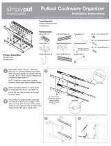
Fully extend slides. Mount 1 – left hand
slide and 1 – right hand slide to the bottom
slide mounting holes in the upright brackets
using 8 – #6-32 X 5/16" screws. Repeat this
process for upper slides (1).
NOTE: There are 4 upper basket mounting
locations. Install upper slides at desired height.
Attach rear slide brackets to upper slides
by pushing bracket firmly onto slides (2).
NOTE: No rear slide brackets are needed
for lower slides.
Place slide and upright bracket assembly
into cabinet so that the front edges of the
slides are flush with the front of the cabinet
opening on the opposite side of cabinet door
hinges. Extend the upper drawer slide.
1
2
3
Tools Required
• Phillips Head Screwdriver
• Tape Measure
Product Assemblies
Parts Included
32
1
Flush
Right Slide
Left Slide
If a half shelf is
present in cabinet
mount the rear
upright bracket
here.

Grand Rapids, MI
800.253.1561
simplyputorganizers.com
©2018 Knape & Vogt. All rights reserved. Knape & Vogt
®
reserves the right to change specifications without notice. 310577/1218
Push the slide back so that the
mounting hole is accessible.
Install 1 – #6 x 1/2" wood
screw (4).
Ensure that upright brackets
are parallel to the front of the
cabinet then attach to the base
of the cabinet with 4 – #8 x 3/4"
wood screws (5A).
NOTE: Screws can be placed
in slotted holes for future
adjustment or in round holes to
ensure the unit does not move.
Push rear slide brackets back
until they are against the back
of the cabinet. Attach to the
back of the cabinet with 3 –
#6 x 1/2" wood screws
per bracket (5B).
Fully extend slides. Install lower
basket to left hand slide by
inserting tabs through the slots
on the wire basket. Next push
basket down into hooks on right
hand slides while supporting the
slide member. Repeat process
for upper basket (6).
NOTE: Install smaller basket on
bottom and larger basket on top.
Using 1-#6-32x5/16" screw
install cross-brace to left-hand
side of front upright bracket
directly below upper basket
slides. Repeat process for
right –hand side of front
upright bracket.
4
5A
5B
6
Left Slide Right Slide
6
5
4
5B
5A
7
7

Cesta superior (1)
Cesta inferior (2)
Soportes verticales (2)
Guías deslizantes izquierdas (2)
Guías deslizantes derechas (2)
Soportes traseros deslizantes (2)
Tornillos
#6-32 x 7.9 mm (5/16") (18)
Tornillos para madera
#8 x 19 mm (3/4") (4)
Tornillos para madera
#6 x 12.7 mm (1/2") (7)
Abrazadera cruzada (1)
SP-DBMUBSC-8-FN
SP-DBMUBSC-11-FN
SP-DBMUBSC-14-FN
SP-DBMUBSC-17-FN
SP-DBMUBSC-20-FN
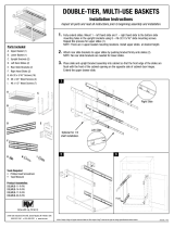
Extienda del todo las guías deslizantes. Fije
1 guía izquierda y 1 derecha a los orificios
inferiores de montaje que hay en los soportes
verticales usando 8 tornillos #6-32 X 7.9 mm
(5/16"). Repita este proceso para las guías
deslizantes superiores (1).
NOTA: Existen 4 posibles ubicaciones
de montaje. Instale las guías deslizantes
superiores a la altura deseada.
Fije los soportes traseros deslizantes a las
guías deslizantes superiores presionándolos
con fuerza sobre las guías (2).
NOTA: No se necesitan soportes traseros
para las guías deslizantes inferiores.
Coloque el conjunto de soporte trasero y
guía deslizante en el armario, de manera que
el borde frontal de las guías queda alineado
con la apertura frontal del armario por el lado
contrario a las bisagras de la puerta del mismo.
Extienda la guía deslizante del cajón superior.
1
2
3
Herramientas necesarias
• Destornillador de estrella
• Cinta métrica
Lista de partes
32
1
nivelar
Cestas multiusos de dos niveles
Instrucciones de Instalación
Inspeccione todas las piezas y lea todas las instrucciones
antes de comenzar con el armado y la instalación.
Assemblages Ensamblaje
de productos
Si hay un medio
estante en el
gabinete, monte
el soporte vertical
trasero aquí.
Guía
deslizante
derecha
Guía deslizante
izquierda

Grand Rapids, MI
800.253.1561
simplyputorganizers.com
©2018 Knape & Vogt. Reservados todos los derechos.El Knape y Vogt
®
reservan el
derecho de cambiar especificaciones sin el aviso. Hecho en los Estados Unidos. 310577/1218
Empuje la guía deslizante hacia
atrás, de manera que pueda
acceder al orificio de montaje.
Coloque 1 tornillo para madera
#6 x 12.7 mm (1/2") (4).
Asegúrese de que los soportes
verticales están paralelos a la
parte frontal del armario cuando
los una a la base del armario
con 4 tornillos para madera
#8 x 19 mm (3/4") (5A).
NOTA: Los tornillos pueden
colocarse en los orificios
ranurados para futuros ajustes,
o en los orificios redondos para
asegurarse de que la unidad no
se mueve.
Empuje los soportes traseros
hacia detrás, hasta que den
contra la parte trasera del
armario. Atorníllelos a la parte
trasera del armario con 3
tornillos para madera
#6 x 12.7 mm (1/2")
por cada soporte (5B).
Extienda del todo las guías
deslizantes. Coloque la
cesta inferior sobre la guías
deslizantes izquierdas
colocando las lengüetas en la
cesta de metal. Luego apriete la
cesta sobre los ganchos de
las guías derechas mientras
sujeta la parte deslizante.
Repita el proceso para la cesta
superior (6).
NOTA: Instale la cesta más
pequeña en la parte inferior y
la cesta más grande en la parte
superior.
Utilizando un tornillo
1-#6-32x5/16", instale la
abrazadera cruzada a la
izquierda del soporte vertical
delantero directamente debajo
de las correderas de la cesta
superior. Repita el proceso
para el lado derecho del
soporte vertical delantero.
4
Guía deslizante
izquierda
5
5B
5A
Guía deslizante
derecha
6 7
4
5A
5B
6
7
/


