Hagerco 2-659-0304 - 6" Round Installation guide
- Category
- Motorcycle Accessories
- Type
- Installation guide
This manual is also suitable for

Wave-To-Open Actuators
Installation Instructions
I-EA00158
Rev -, Rev Date: 2/15/16
Always visit www.hagerco.com for the latest Installation Instructions
HAGER COMPANIES 139 Victor Street, St. Louis, MO 63104 • (800) 325-9995
DEVICES COVERED IN THIS DOCUMENT:
2-659-0303 - 6" Rnd Text & Logo 2-659-0305 – 4.75" Sqr Text & Logo
2-659-0304 - 6" Rnd Logo Only 2-659-0306 – 4.75" Sqr Logo Only
2-659-0307 - 6" Rnd Text Only 2-659-0308 – 4.75" Sqr Text Only
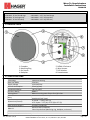
1. DESCRIPTION
2. SPECIFICATIONS
1. Faceplate
2. Mounting Ring
3. Set Screws
4. Backplate
5. NEMA 4 Enclosure
6. Wire Harness
7. DIP Switches
8. Potentiometer
Technology Capacitive Sensing
Detection Mode Proximity
Supply Voltage 12-24 VAC/VDC
Current Consumption 37 mA (typical)
Temperature Range -20°F to +120°F
Enclosure Rating NEMA 4
Sensing Zone* Maximum sesing zone of up to four (4) inches
Relay
1-Form A Solid State Relay
0.4A 60 VAC/VDC (max)
Dimensions (Overall)
6" Round - 7" (Dia) x 0.5" (D)
4.75" Square - 5.75" (H) x 5.75" (W) x 0.5" (D)
Wire Harness Length** 6 inches (5 conductor)
Material
Stainless Steel (Faceplate)
Clear Polycarbonate (Mounting ring, backplate, enclosure)
*Sensing Zone is dependent upon: Size(area), Orientation, and Speed of object and Environmental conditions
**5 Conduct wire needed between sensor and door control
Page 1 of 3

Wave-To-Open Actuators
Installation Instructions
I-EA00158
Rev -, Rev Date: 2/15/16
Always visit www.hagerco.com for the latest Installation Instructions
HAGER COMPANIES 139 Victor Street, St. Louis, MO 63104 • (800) 325-9995
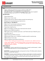
3. INSTALLATION
TIPS
Single or double gang electrical box may be used (non-metallic ideal)
Single gang electrical box recommended for 4.75" square version
Set screws are 4/40 x ½” hex head screws, adjusted with 3/32" hex wrench (supplied)
Supplied mounting screws are #6-32 x ½” Flat Phillips head screws
FUNCTIONALITY
ACTIVATION - Activation signal held until sensing zone is cleared (or until relearned). Audible
Alert (if enabled) will pulse for 0.5 seconds at initial detection
REJECTION - An object must be within sensing zone for at lease 130 milliseconds for detection
to occur (i.e. parallel traffic rejection).
TRACKING - Reduced unwanted detections by allowing small variations in baseline capacitance
(i.e. temperature/humidity changes). If stationary object remains within sensing zone for more
than 5 seconds, a new capacitive zone will be learned and normal operation will resume (i.e.
chewing gum stuck to faceplate).
1) Install electrical box.
2) Remove two (2) set screws.
3) Disassemble (slide up, pullout) faceplate assembly from mounting ring.
4) Temporaryily mount mounting ring to electrical box.
NOTE: Observe “THIS END UP”.
5) Mark four (4) mounting ring mounting hole locations.
6) Remove mounting ring from electrical box.
7) Install four (4) wall anchors.
8) Mount (hand tighten) mounting ring to both electrical box and wall.
9) Remove back of NEMA 4 enclosure.
10) Complete Section 4 (WIRING) and Section 5 (SETTINGS AND ADJUSTMENTS) prior to
proceeding to step 11.
11) Reinstall back of NEMA 4 enclosure.
12) Reassemble (Align, push in, slide down) faceplate assembly to mounting ring.
13) Reinstall two (2) set screws.
14) Test installation functionality and performance.
CAUTION: When installing near unprotected and/or uninsulated circuits, additional electrical
isolation may be needed. The shrink tubing provided over the printed wiring board is rated
minimum 150V, VW-1 and 80°C. This information may be taken into account to define whether
additional insolation is required.
INSTALLATION
Page 2 of 3

Wave-To-Open Actuators
Installation Instructions
I-EA00158
Rev -, Rev Date: 2/15/16
Always visit www.hagerco.com for the latest Installation Instructions
HAGER COMPANIES 139 Victor Street, St. Louis, MO 63104 • (800) 325-9995
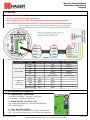
4. WIRING
IMPORTANT WIRING NOTES:
Be sure to always use the provided isolation module. *
If using a shielded wire harness, both ends of the shielding foil must be connected to Earth Ground.
If using a wire harness with more than 5 conductors, all extra conductors must be wired to Earth Ground.
NOTE: It will take approximately 10 seconds to complete the initialization sequence once powered.
* It is required that each Touchless Switch be powered by a separate (included) isolation module.
5. SETTING & ADJUSTMENTS
Isolation Module Signal Harness Wire Isolation Module Wire Door Control Terminal
AC/DC + - Red AC/DC +
AC/DC - - Black AC/DC -
COM - White ACT COM
NO - Green ACT NO
NC - Yellow ACT NC
Earth Ground - Green/Yellow Earth Ground
AC/DC Red Red -
AC/DC Black Black -
COM White White -
NO Green Green -
Earth Ground Blue Blue -
To Door Control
(6 wire side)
To Touchless
Switch
(5 Wire Side)
Wire nut harness wires and isolation module wires together and connect isolation module wires to the door control, according to the chart below.
A – SENSING ZONE – potentiometer
COUNTERCLOCKWISE – decrease (0" minimum)
CLOCKWISE – increase (4" maximum *)
B – AUDIBLE ALERT – DIP switch 1 (left)
ON – audible alert pulsed for 0.5 seconds during detection
OFF – audible alert off
C – LED – DIP switch 2 (RIGHT)
ON – LED on at rest, pulsed off for 0.5 seconds during detection
OFF – LED off at rest, pulsed on for 0.5 seconds during detection
Page 3 of 3
-
 1
1
-
 2
2
-
 3
3


Hagerco 2-659-0304 - 6" Round Installation guide
- Category
- Motorcycle Accessories
- Type
- Installation guide
- This manual is also suitable for
Ask a question and I''ll find the answer in the document
Finding information in a document is now easier with AI
Related papers
-
Hagerco 2-659-0308 - 4.75" Square Installation guide
-
-
-
-
-
Hagerco 2-659-0335 / 2-659-0336 - Superscan Active Infrared Safety Sensor Door Mounted Installation guide
-
-
-
-
Other documents
-
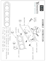 Yosemite Home Decor 4504SN Installation guide
-
Hager 8300 series Installation and Service Manual
-
BEA MS21 User guide
-
-
-
-
-
-
-
