1
2
3
4
5
6
7
8
MAGIC SWITCH: MS21H
75.5737.12 MS21H 20201014 Page 1 of 4
1. faceplate
2. mounting holes
3. set screws
4. backplate
5. NEMA 4 enclosure
6. wire harness
7. DIP-switches
8. potentiometer
PRODUCT FAMILY
6” ROUND STYLES 4.75” SQUARE STYLES
10MS21HR
text only
10MS21HS
text only
10MS21HRLL
logo only
10MS21HSLL
logo only
10MS21HR1
text & logo
10MS21HS1
text & logo
Technology capacitive sensing
Detection Mode proximity
Supply Voltage 12 – 24 VAC/VDC
Current Consumption 37 mA (typical)
Temperature Range -20 – 120 °F
Enclosure Rating NEMA 4
Sensing Zone 0 – 4”
Sensing Zone is dependent upon size (area) of object, orientation of object, speed of
object, and environmental conditions.
Relay 1-Form A Solid State Relay
0.4A 60 VAC/VDC (max)
Dimensions (0verall) 6” Round:
4.75” Square:
7” (diameter) × 0.5” (D)
5.75” (H) × 5.75” (W) × 0.5” (D)
Wire Harness Length 6 inches (5-conductor)
A 5-conductor wire is needed between the sensor and the door control.
Material stainless steel (faceplate)
clear polycarbonate (mounting ring, backplate, enclosure)
Specifications are subject to change without prior notice.
All values measured in specific conditions.
TECHNICAL SPECIFICATIONS
ENGLISH
Hardwired, Stainless Steel, Touchless,
Activation Sensor
Visit website for
available languages of
this document.
DESCRIPTION

1
2
Page 2 of 4 75.5737.12 MS21H 20201014
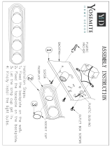
APPLICATIONS TIPS
1. Install the electrical box.
2. Remove the two (2) set screws.
3. Disassemble (i.e. slide up and pull out) the faceplate assembly from the mounting ring.
4. Temporarily mount the mounting ring to the electrical box. Pay attention to “THIS END UP”.
5. Mark four (4) hole locations for installing the mounting ring.
6. Remove the mounting ring from the electrical box.
7. Install four (4) wall anchors.
8. Mount (i.e. hand-tighten) the mounting ring to both the electrical box and the wall.
9. Remove the back of the NEMA 4 enclosure.
10. Sections 2 (WIRING) and 3 (SETTINGS & ADJUSTMENTS) must be completed prior to continuing installation
(Section 4).
Single Swing Doors Dual Egress Swing DoorsSim Pair Swing Doors Sliding Doors
IMPORTANT WIRING NOTES:
• Always use a BEA-provided isolation module (polarity-sensitive) for powering each MS21.
Red must be connected to power (+) and black connected to power (-).
• It is recommended that 300 V, low-voltage cabling, shielded wire be used during installation.
• It is recommended that the MS21 cabling have a distance of 6 inches around power lines 120 VAC/VDC
or higher.
• If using a wire harness with more than 5 conductors, all extra conductors must be wired at both ends to
Earth Ground.
INSTALLATION
WIRING
Only trained and qualified
personnel are recommended to
install and set up the sensor.
The warranty is invalid if
unauthorized repairs are made
or attempted by unauthorized
personnel.
Always test the proper
operation of the installation
before leaving the premises.
PRECAUTIONS
NOTE: Do not install the sensor within the swing path of the door.
• Single gang or double gang electrical boxes (ideally, non-metallic) may be used.
• Single gang electrical boxes are recommended for 4.75” square version.
• Set screws are 4/40 × 1/2” Allen head screws, adjusted with 3/32 Allen wrench (supplied).
• Mounting screws are #6-32 × 1/2” Phillips head screws.

3
A
B C
2
75.5737.12 MS21H 20201014 Page 3 of 4
GREEN
YELLOW
RED
BLACK
WHITE
RED
BLACK
WHITE
GREEN
BLUE
Installer Provided
Wire Harness
ISOLATION
MODULE
RED
BLACK
WHITE
BLUE
WIRE NUT
NO
COM
− POWER
+ POWER
NC
EARTH GROUND
GREEN / YELLOW
GREEN
DOOR HEADER
Isolation Module Signal Harness Wire Isolation Module Wire Door Control Terminal
To Door Control
(6-wire side)
AC/DC + - Red AC/DC +
AC/DC - - Black AC/DC -
COM - White ACT COM
NO - Green ACT NO
NC - Yellow ACT NC
Earth Ground - Green / Yellow Earth Ground
To MS21
(5-wire side)
COM White White -
NO Green Green -
AC/DC Red Red -
AC/DC Black Black -
Earth Ground Blue Blue -
It will take approximately 10 seconds to complete the initialization sequence once powered.
Wire-nut harness wires and isolation module wires together and then connect the isolation
module wires to the door control using the chart or visual representation below.
NOTE: From isolation module to ACT, use either green (NO) OR yellow (NC).
(A) SENSING ZONE – potentiometer
COUNTERCLOCKWISE – decrease (0’’ minimum)
CLOCKWISE – increase (4’’ maximum)
1
(B) AUDIBLE ALERT – DIP-switch 1 (left)
ON – audible alert pulsed for 0.5 seconds during detection
OFF – audible alert off
(C) LED – DIP-switch 2 (right)
ON – LED on at rest, pulsed off for 0.5 seconds during detection
OFF – LED off at rest, pulsed on for 0.5 seconds during detection
SETTINGS & ADJUSTMENTS
NOTES:
1. Maximum Sensing Zone will vary depending on size (area), orientation, and speed of object as well as environmental conditions.
WIRING (cont.)

4
Page 4 of 4 75.5737.12 MS21H 20201014
BEA, Inc., the sensor manufacturer, cannot be held responsible for incorrect installations or inappropriate adjustments of the sensor/device; therefore,
BEA, Inc. does not guarantee any use of the sensor outside of its intended purpose.
BEA, Inc. strongly recommends that installation and service technicians be AAADM-certifi ed for pedestrian doors, IDA-certifi ed for doors/gates, and
factory-trained for the type of door/gate system.
Installers and service personnel are responsible for executing a risk assessment following each installation/service performed, ensuring that the sensor
system installation is compliant with local, national, and international regulations, codes, and standards.
Once installation or service work is complete, a safety inspection of the door/gate shall be performed per the door/gate manufacturer recommendations
and/or per AAADM/ANSI/DASMA guidelines (where applicable) for best industry practices. Safety inspections must be performed during each service
call – examples of these safety inspections can be found on an AAADM safety information label (e.g. ANSI/DASMA 102, ANSI/DASMA 107).
Verify that all appropriate industry signage and warning labels are in place.
BEA, INC. INSTALLATION/SERVICE COMPLIANCE EXPECTATIONS
Tech Support & Customer Service: 1-800-523-2462
General Tech Questions: [email protected] | Tech Docs: www.BEAsensors.com
©BEA | Original Instructions | PLEASE KEEP FOR FURTHER USE - DESIGNED FOR COLOR PRINTING
Can’t find your answer? Visit www.beainc.com or
scan QR code for Frequently Asked Questions!
Sensor erratically detecting
or falsely activating
Not properly grounded Verify continuity between sensor ground
and earth ground.
See Application Note for details.
Unstable power supply Ensure the BEA isolation module (polarity-
sensitive) is being used with each MS21.
Electrical noise within sensing
zone
Reduce sensing zone (potentiometer
counterclockwise).
Non-stationary object within
detection zone
Clear a 10” zone around detection field.
Sensor not detecting Sensing zone is set too low Increase sensing zone (potentiometer
clockwise).
No power Verify power supply and connection.
TROUBLESHOOTING
FUNCTIONALITY
ACTIVATION
Activation signal held until sensing zone is cleared (or relearned). Audible Alert (if
enabled) will pulse for 0.5 seconds at initial detection.
REJECTION
An object must be within sensing zone for at least 130 milliseconds for detection to occur
(i.e. parallel traffic rejection).
TRACKING
Reduced unwanted detections by allowing small variations in baseline capacitance (e.g.
temperature/humidity changes). If stationary object remains within sensing zone for more
than 5 seconds, a new capacitive zone will be learned and normal operation will resume
(e.g. chewing gum stuck to faceplate).
FINAL INSTALLATION
1. Reinstall the back of the NEMA 4 enclosure.
2. Reassemble (i.e. align, push in, and slide down) the faceplate assembly to the mounting ring.
3. Reinstall the two (2) set screws.
4. Test the installation functionality and performance.
CAUTION:
When installing near unprotected and/or uninsulated circuits, additional electrical isolation
may be needed. The shrink tubing over the printed wiring board (provided by BEA) is rated
minimum 150V, VW-1, and 80 °C. This information may be taken into account to define
whether additional isolation is required.
/