Page is loading ...

Features
· Keypad programmable
· 500 user codes
· 1 to 6 digit user codes
· 4 independent outputs
· 4 independent timers
· 2 Form C relay contacts
· 2 solid state open collector outputs
· Program entry codes to activate one or
two relays
· Disable input
· Door sense input
· Request-to-exit/enter input
· Keypad tamper lockout
· Timed anti-passback
· Anti-tailgate
· Two LED status indicators
· Tactile key feel
· Audible code entry verification
· 12 or 24V, AC or DC operation
The 2916 Indoor/Outdoor Keypad Surface Mount is a digital keyless entry
system designed for access control applications. The keypad is integrated
in a heavy cast vandal resistant housing, designed to be mounted on a
rugged, surface mounting plate and may be mounted in a standard
single-gang electrical box. The indoor/outdoor backlit keys have bright,
easy-to-read graphics.
Up to 500 entry codes, from 1 to 6 digits in length, can be programmed.
They can activate either, or both of the relay outputs. The “anti-
passback” feature prevents using the same code again before the
programmed time elapses.
All system indicators are long-lasting, solid state LEDs. Two indicators
show the status of the entry system. The left indicator lights red to
indicate power, then turns green when access is granted. The right
indicator lights yellow when the keypad is in “lockout” condition (from too
many incorrect code entries). The yellow LED flashes when the keypad is
in programming mode. An internal sounder beeps when each key is
pressed. An internal jumper sets the sounder volume high or low
The SENSE input can be used two ways. If programmed for “door
sense” the input is wired to a normally closed switch on the door to detect
when the door is opened or closed. Forced entry or door ajar situations
can then be detected. Using door sense, the “Auto-relock” feature will
prevent “tailgating” by turning off the Main Relay output immediately
when the door is closed after access has been granted. If the SENSE
input is programmed for “inhibit”, the input can be wired to a “service”
switch or automatic timer that will disable the Main Relay when required.
The REQUEST-TO-EXIT input can be wired to a pushbutton to provide
codeless activation of Main Relay, Auxiliary Relay, Output #3 or Output
#4 (programmable).
The ALARM SHUNT output activates when access is granted. This
output can be wired to shunt alarm contacts on the access door/gate to
prevent triggering of an alarm when authorized access occurs.
The 2916 is powered from a 12-24V AC or DC source. The EEPROM
memory retains all entry codes and programming, even without power.
An internal jumper is provided to reset the master code. The Main Relay
has a 5 Amp capacity. The Auxiliary Relay has a 2 Amp capacity. Two
solid state outputs, capable of switching 100 mA to common, are
programmable to signal forced entry, door ajar, lockout, alarm circuit
shunting, request-to-exit, and keypad active conditions.
INSTALLATION INSTRUCTIONS
2916
SPECIFICATIONS
Mechanical
Dimensions: 3.00" W x 5.75" H x 1.375" D
(1.4375” wall projection)
Electrical
Input Voltage: 12-24 Volts AC or DC
Operating Current: 30 mA typical, 150 mA max
Output Ratings
Main Relay: Form “C” 5 Amps @ 28 Volts max
Auxiliary Relay: Form “C” 2 Amp @ 28 Volts max
Type: Solid state outputs (Outputs #3 & #4)
Short-to-common 100 mA @ 24 VDC maximum
Environmental
Temperature: -22°F to 149°F (-30°C to 65°C)
Humidity:5% to 95% non-condensing
Security Door Controls
2916 Keypad
Installation Instructions
S-EA00080
5/7/2012
HAGER COMPANIES 139 Victor Street, St. Louis, MO 63104 ● (800) 325-9995
1

QuickStart Programming
To enter Programming Mode, enter #9# plus the Master Code. The yellow indicator will blink slowly showing that the 2916 is in programming mode.
Use the option codes to program each function. After the new data entry is complete for each function , the yellow indicator will flash quickly while the
data is being stored and the green indicator will light briefly if the programming has been accepted. The red indicator will light if any programming
data is entered incorrectly or the function is rejected. If a red indicator is seen, the entire function (option code + data) will have to be fully re-entered.
Test your new user code
Enter user code ‘9876’. The green indicator should illuminate, the main relay
should activate and the door should unlock for 5 seconds.
Program the first user code
Step 1. Enter: #9# 123456 Enter the program mode (default master code)
Step 2. Enter: 03# 4# Set the entry code length to 4 digits
Step 3. Enter: 21# 5# Set the main relay activate time to 5 sec.
Step 4. Enter: 01# 9876# 9876# 1# Set user code ‘9876’ to activate the main relay
Step 5. Enter: # Exit programming mode
**
Adding additional user codes
Once the code length and relay time have been set you do not need to set them each time you
additional users.
To add additional users:
Step 1. Enter: #9# 123456 Enter the program mode (default master code)
Step 2. Enter: 01# 2222# 2222# 1# Set user code ‘2222’ to activate the main relay
Step 3. Enter: 01# 3333# 3333# 1# Set user code ‘3333’ to activate the main relay
Step 4. Enter: # Exit programming mode
**
Deleting a user code
To delete a user:
Step 1. Enter: #9# 123456 Enter the program mode (default master code)
Step 2. Enter: 02# 3333# 3333# User code ‘3333’ has been deleted.
Step . Enter: # Exit programming mode
**
CAUTION
IF THE UNIT IS AC POWERED, MAKE SURE
THAT THE SECONDARY OF THE SYSTEM IS
ISOLATED FROM EARTH GROUND
!
!
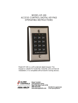
Fig. 2 Wiring Diagram
E
1
E
2
E
3
E
4
E
5
E
6
E
7
E
8
SENSE
GROUND
REQUEST TO EXIT
GROUND
GROUND
OUTPUT 3
OUTPUT 4
GROUND
BLACK
GREEN
BLUE
BLACK
BLACK
VIOLET
BLACK
GRAY
C
N/O
N/C
C
N/O
N/C
N/C DOOR
POSITION
SWITCH
N/O
REQUEST
-TO-EXIT
SWITCH
EARTH
GROUND
CONNECTION
AUXILIARY OUTPUTS
100mA MAX TO
COMMON
TO POWER SUPPLY
FAIL SECURE
CONNECTION
FAIL SAFE CONNECTION
AUXILIARY RELAY
2 AMPS @ 28VDC
MAX
KEY PAD POWER
12-24 VOLTS
AC OR DC
MAIN RELAY
5 AMPS @ 28VDC
MAX
}
}
}
+
-
NO
COM
NC
NO
NC
COM
GRAY
GREEN
ORANGE
BLUE
WHITE
YELLOW
BLACK
RED
POWER
BEEPER
LEVEL
JUMPER
(JP1)
WIRE
HARNESS
(E1-E8)
MAIN
AUXILIARY
MASTER CODE
RESET JUMPER
(JP2)
BACK
Security Door
Controls
RED/GREEN
POWER/ACCESS
INDICATOR
YELLOW
“LOCKOUT/
PROGRAM”
INDICATOR
KEYPAD
FRONT
2916 Keypad
Installation Instructions
S-EA00080
2916 TERMINALS
5/7/2012
HAGER COMPANIES 139 Victor Street, St. Louis, MO 63104 ● (800) 325-9995
2

KEYPAD WIRING
See Fig. 3 for an example of a basic door installation. The keypad is
mounted adjacent to the door. An electric door strike is mounted in the
door jamb to release the door lock. A magnetic switch is mounted on top
of the door jamb for detecting when the door is open.
Use the following steps to wire the keypad. Refer to the wiring diagram
shown in Fig. 4 to assist in the wiring.
Note: Up to 500 feet of 18 AWG wire can be run for power, use larger
wire for longer runs. Use 22 AWG or larger (depending on load) for other
connections.
Output
q Install a low voltage electric door strike for unlocking the door.
q Route two wires between the door strike and the keypad box.
Connect the (+) door strike wire to the keypad’s MAIN RELAY N.O.
yellow wire. Connect the other door strike wire to the keypad’s PWR
black wire (-). Connect a wire between the keypad’s PWR red wire
(+) and the MAIN RELAY COM white wire.
Power
q Choose a location for the power supply or transformer.
q Route two wires between the door strike and the keypad box.
Connect the power supply’s output terminals to the keypad’s PWR
red (+) and black (-) input wires.
Observe wiring polarity if using DC.
Caution: If the unit is AC powered, make sure the secondary of
the system transformer is isolated from earth ground.
Earth Ground
q To avoid damage to the unit from static discharges, connect the
EARTH GROUND black wires E1, 4, 5 or 8 to a good earth grounding
point. Suggested wiring size is 18 AWG for earth ground.
Sense Input
RE
Note: SENSE terminal (gray wire) can be programmed for either a
door sense or inhibit input. Both features cannot be used at the same
time. If you are not using the sense input, program the input for inhibit.
q To use the door sense feature to detect forced entry or door ajar
conditions, install a
normally closed
door switch on the door and
route two wires from the switch to the keypad box. Connect the
door switch to the keypad’s SENSE terminal (gray wire E8) and COM
terminal (any black wire).
q If an inhibit switch or timer is going to be used for temporarily
disabling the keypad, route two wires from the switch or timer to the
keypad box. Connect the inhibit switch/timer
normally open
terminals to the keypad’s SENSE (gray wire E8) and COM (black
wires) terminal.
Request-to-Exit Input
(wiring shown on page 3, fig. 4)
q If a request-to-exit pushbutton is going to be used, route two wires
from the keypad box to a normally open pushbutton mounted on the
secure side of the door. Connect the wires to the pushbutton and to
the keypad’s REX (violet wire E6) and COM (black wires) terminals.
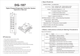
Solid State Outputs
The two solid state outputs (Outputs #3 & #4) can be programmed to
activate during various conditions. These outputs can be used to activate
indicators or sounders. See fig. 5 for wiring examples using the solid state
outputs.
Fig. 5 Using Solid State Outputs
Fig. 3 Basic Door Installation
OUTPUT #3 LIGHTS AN LED
OUTPUT #4 LIGHTS AN LED AND SOUNDS A BEEPER
EXAMPLE
#1:
POWER
SUPPLY
+
LED
LED
BLUE
GREEN
1KΩ
1KΩ
-
+
OUTPUT #3
OUTPUT #4
ELECTRONIC
BEEPER
OUTPUT #3 LIGHTS A LAMP POWERED FROM AN EXTERNAL SOURCE
OUTPUT #4 TRIGGERS A NORMALLY OPEN ALARM PANEL ZONE
EXAMPLE
#2:
BLUE
GREEN
OUTPUT #3 COM
OUTPUT #4 COM
POWER
SOURCE
OUTPUT #3
END OF LINE
RESISTOR
ALARM PANEL
NO ZONE
COMMON
LOW
VOLTAGE
LAMP
-
+
BLACK
BLACK
OUTPUT #4
EACH
OUTPUT
100 mA
MAXIMUM
Wire
Pigtail
Wire
Pigtail
Fig. 4 Basic Door Installation Wiring
GRAY
BLACK
BLACK
BLACK
BLACK
BLUE
GREEN
VIOLET
C
NC
NO
C
NC
NO
NC DOOR
POSITION SWITCH
NO REQUEST-TO-
EXIT SWITCH
SENSE
GROUND
REQUEST-TO-EXIT
GROUND
GROUND
GROUND
OUTPUT
OUTPUT
EARTH GROUND
CONNECTION
WIRES
E
1
E
2
E
3
E
4
E
5
E
6
E
7
E
8
TO POWER SUPPLY
FAIL SECURE CONNECTION
FAIL SAFE CONNECTION
AUXILIARY RELAY
2 AMPS @ 28VDC
MAX
KEY PAD POWER
12-24 VOLTS
AC OR DC
MAIN RELAY
5 AMPS @ 28VDC
MAX
}
}
}
+
-
NO
COM
NC
NO
NC
COM
GRAY
GREEN
ORANGE
BLUE
WHITE
YELLOW
BLACK
RED
2916 Keypad
Installation Instructions
S-EA00080
2916
keypad
5/7/2012
HAGER COMPANIES 139 Victor Street, St. Louis, MO 63104 ● (800) 325-9995
3

FACTORY DEFAULTS
Master Programming Code………..………………….….…...123456
Entry Code Length……………………………………….……..4 digits
Request-to-exit Output Relay……………………….........Main Relay
Alarm Shunt Output….………………………………….........Disabled
Forced Entry Output……………………………..…………..Output #3
Door Ajar Output…………………………………..………...Output #4
Main Relay On Time………………………………...……..60 Seconds
Auxiliary Relay On Time………………………………...…60 Seconds
Solid State Output #3 On Time………………………..….60 Seconds
Solid State Output #4 On Time…………………………...60 Seconds
Door Sense/Inhibit Input…………………………...……..Door Sense
Keypad Lockout Output………………………………..…….Disabled
Keypad Active Output………………………………..…..…..Disabled
Beeper Sounds When Key Pressed……………………...………Yes
Beeper Sounds During Relay #1………………………..…...…….No
Beeper Sounds During Relay #2……………………………...…...No
Beeper Sounds During Output #3……………………………….....No
Beeper Sounds During Output #4……………………………........No
Keypad Lockout Count……….………......….3 Tries Before Lockout
Anti-Passback Time………………..……...……….No Anti-Passback
Auto-Relock…………………………………...………….………….On
BASIC PROGRAMMING
When the 2916 is in Programming Mode, both indicators will turn
off until programming begins. After a programming option
number is entered, the yellow indicator will blink. This shows that
the 2916 is ready to accept the new programming data. After the
new data entry is complete, the yellow indicator will flash while
the data is being stored. The green indicator will light if the data
is accepted. The red indicator will light if any programming data
is entered incorrectly, and the command will have to be fully re-
entered.
Entering Programming Mode
The 6-digit Master Programming Code (default = 123456) is used
to enter Programming Mode.
Press: # 9 # Master Code
Master Code = the current 6-digit Master Programming Code
Setting Entry Code Length Default: 4 digits
Press: 0 3 #
Length
#
Length = 1-6 for entry code length
Note: If the Entry Code Length is going to be changed from the
factory default of 4 digits, make this change first before
programming any entry codes.
Adding a New Entry Code
Press: 0 1 #
Code
#
Code # Relay #
Code=The new entry code: 1-999999, depending on code length
Relay=Relay output entry code will activate:
1=Main Relay 2=Auxiliary Relay 3=Both Relays
10=Relay #1, toggled 20=Relay #2, toggled 30=both Relays
toggled
12=Relay #1 toggled; Relay #2 timed open
21=Relay #1 timed open; Relay #2 toggled
The yellow indicator will flash quickly while the 2916 searches its
memory for available space and duplicate entries. The green
indicator will light when the new code is stored.
If the new entry code chosen is already being used for another entry
code, the red indicator will light. A new unique code needs to be
entered.
Note: Leading zeros (zeros before the code number, i.e.0001) do
not need to be entered when programming a new code. The 2916
will internally add any zeros to fill digits determined by the entry
code length setting. Leading zeros will have to be entered by the
user when entering their code to gain access.
Erasing a Single Entry Code
Press: 0 2 #
Code
#
Code
#
Code=The entry code to delete
The yellow indicator will flash quickly while the 2916 searches its
memory for the code to erase. The green indicator will light when
the code is erased.
Erasing All Entry Codes
WARNING: PERFORMING THIS COMMAND WILL REMOVE
ALL ENTRY CODES FROM THE MEMORY
Press: 9 7 # 0 0 0 0 0 0
# 0 0 0 0 0 0
#
Note: The green indicator will light while the memory is being
erased. This may take up to 15 seconds.
Changing the 6-Digit Master Programming Code
Press: 9 8 #
Master
Code
#
Master Code
#
Master Code=The new 6-digit Master Programming Code
New master code: ____________
PROGRAMMING OPTIONS
There are several 2916 programming options. For most
installations, the factory set default options are sufficient. The
keypad must be in Programming Mode to make these changes.
Programming the 2916 To Hold the Output
The 2916 has a “Toggle Mode” available for each relay and solid-state output.
When an output is programmed for Toggle Mode, the output alternates from
OFF to ON or from ON to OFF each time it is activated. When output is toggled
on, the green LED flashes until toggled off.
The rules for a toggle output are:
· If the output is OFF, it will turn ON and stay on until the next activation.
· If the output is ON, it will turn OFF and stay off until the next activation.
Re-entering a Command After a Mistake
If the red indicator lights, signaling an incorrect entry, or an
incorrect key is pressed during programming, to clear the keypad
and re-enter the command:
Press:
9 #
*
2916 Keypad
Installation Instructions
S-EA00080
Exiting Programming Mode
Press: **
#
The red indicator will light after exiting Programming Mode
Note: The 2916 will automatically exit Programming Mode after
two minutes of inactivity
5/7/2012
HAGER COMPANIES 139 Victor Street, St. Louis, MO 63104 ● (800) 325-9995
4

Select Door Sense or Inhibit Input Default: Door Sense
The input (gray wire) can be programmed for DOOR SENSE or
INHIBIT.
Press: 1 0 # Input #
Input=0 for Door Sense; =1 for Inhibit
When programmed for DOOR SENSE, if an open condition on the
input occurs before access is granted (with an entry code or with the
request-to-enter input) a FORCED ENTRY output will occur. If an
open condition remains 60 seconds after a relay activation for access,
a DOOR AJAR output will occur.
When programmed for INHIBIT, a closed condition on the input will
prevent Relay #1 from activating when access is requested with an
entry code. This mode is typically used with an external timer to
disable the access device at certain times.
Select Forced Entry Output Default: Output #3
Sets which output activates if the DOOR SENSE input opens before
access is granted. This output is not timed.
Press: 1 1 # Output #
Output=Output to Activate(0-4)
1=Main Relay; 2=Auxiliary Relay; 3=Output #3; 4=Output #4;
0=No Output
Select Door Ajar Output Default:
Output #4
Sets which output activates if the DOOR SENSE input stays open 60
seconds after access is granted. This output is not timed.
Press: 1 2 # Output #
Output=Output to Activate (0-4)
1=Main Relay; 2=Auxiliary Relay; 3=Output #3; 4=Output #4;
0=No Output
Select Keypad Active Output Default: No Output
Sets which output activates when any keys are pressed. This output is
timed. If toggle mode is selected for the output, the timer value
defaults to 2 seconds.
Press: 1 4 #
Output
#
Output=Output to Activate(0-4)
1=Main Relay; 2=Auxiliary Relay; 3=Output #3; 4=Output #4;
0=No Output
Select Keypad Lockout Output Default: No Output
Sets which output activates when the keypad is “locked out” after too
many incorrect entry code attempts. The lockout time is 60 seconds.
Press: 1 3
#
Output
#
Output=Output to Activate (0-4)
1=Main Relay; 2 = Auxiliary Relay; 3=Output #3; 4=Output #4;
0=No Output
Select Alarm Shunt Output Default: No Output
Sets which output activates during the time access is granted. (Use
this output ot shunt alarm contacts attached to the access door.) This
output may be timed or toggled.
Press: 1 5 #
Output
#
Output=Output to Activate(0-4)
1=Main Relay; 2=Auxiliary Relay; 3=Output #3; 4=Output #4;
0=No Output
Select Request-to-Exit Output Default: No
Sets which output activates when the Request-to-Exit input is
grounded. This output may be timed or toggled.
Press: 1 6 #
Output
#
Output=Output to Activate(0-4)
1=Main Relay; 2=Auxiliary Relay; 3=Output #3; 4=Output #4;
0=No Output
REX input terminates toggle of Main Relay
Main Relay On-time Default: 60 Seconds
Sets the length of time the Main Relay activates when triggered.
Green LED is on when Main Relay is active.
Press: 2 1 #
Seconds
#
Seconds=Output time in seconds (0-60)
Auxiliary Relay On-time Default: 60
Seconds
Sets the length of time the Auxiliary Relay activates when triggered.
Press: 2 2 #
Seconds
#
Seconds=Output time in seconds (0-60)
Solid-state Output #3 On-time Default: 60 Seconds
Sets the length of time Output #3 activates when triggered.
Press: 2 3 #
Seconds
#
Seconds=Output time in seconds (0-60), 99=Toggle Mode
(Typical Programming cont.)
Program all normal entry codes to use the Main Relay (Relay #1),
and only Relay #1 as the output relay. Program the code(s) that you
want to use to hold the output for an indefinite period to the
Auxiliary Relay (Relay #2). See the following example that sets entry
codes 1234 for normal and 5678 for toggle operation.
Press: 0 1 # 1 2 3 4 # 1 2 3 4 # 1 #
01=Programming Step; 1234=Entry Code; 1=Main Relay
Press: 0 1 # 5 6 7 8 # 5 6 7 8 # 20 #
01=Programming Step; 5678=Entry Code; 20=Auxiliary Relay
Typical Toggle Mode Wiring
For devices triggered by a normally open circuit, wire the contacts of
the Main and Auxiliary Relays in parallel (see the Figure below).
Either relay will be able to trigger the access device. Entry codes
programmed for the Auxiliary Relay will be able to hold the output
on.
Toggle
2916 Keypad
Installation Instructions
S-EA00080
MAIN
RELAY
AUXILIARY
RELAY
920
OUTPUT
S
EITHER RELAY CAN
TRIGGER THE ACCESS
DEVICE
ACCESS
DEVICE
NO
COMMON
NC
NO
COMMON
NC
YEL
WHT
ORG
GRN
5/7/2012
HAGER COMPANIES 139 Victor Street, St. Louis, MO 63104 ● (800) 325-9995
5

Beep Sounds During Auxiliary Relay Default: No
Selects whether or not the keypad beeps during Auxiliary Relay activation.
Press: 4 2 #
Sound
#
Sound=1 for Yes, =0 for No
Beep Sounds During Output #3 Default: No
Selects whether or not the keypad beeps during Output #3 activation.
Press: 4 3 #
Sound
#
Sound=1 for Yes, =0 for No
Beep Sounds During Output #4 Default: No
Selects whether or not the keypad beeps during Output #4 activation.
Press: 4 4 #
Sound
#
Sound=1 for Yes, =0 for No
Keypad Lockout Count Default: 3 Tries
Sets the number or incorrect entry code attempts allowed before the
keypad “locks out”.
Press: 5 0 # Attempts
#
Attempts=Number of attempts before lockout (2-7)
Anti-Pass Back Time Default: No Anti-Pass Back
Sets the length of time an entry code will not function after it is used.
Press: 5 1 # Minutes
#
Minutes=Time in minutes (1-4), 0=No Anti-passback
RESETTING KEYPAD
Master Reset
CAUTION: Performing a master reset will clear the entire
memory of the 2916 and return all programmable options to
the factory default values. ALL ENTRY CODES WILL BE
ERASED.
STEP 1 Disconnect power from the keypad.
STEP 2 Press and hold down the * and # keys.
STEP 3 Apply power to the keypad, continue holding the keys
down until the red indicator starts flashing
STEP 4 Release the keys. The red and yellow indicators will
remain lit until the process is complete, then the
yellow indicator will go out.
Resetting the Master Code
STEP 1 Remove the 2916 from the wall..
STEP 2 Locate jumper at JP2. This jumper is used to reset
the master code.
STEP 3 With power applied to the keypad, remove the jumper
at JP2. The keypad will begin to beep, signaling that the code has
been reset.
STEP 4 Replace jumper on JP2
THE MASTER PROGRAMMING CODE IS NOW 123456.
Beeper Sound Level
The Keypad’s beeper can be set to high or low level.
Remove jumper JP1 to reduce beeper sound level.
Beep Sounds During Main Relay Default: No
Selects whether or not the keypad beeps during Main Relay activation.
Press: 4 1 #
Sound
#
Sound=1 for Yes, =0 for No
Solid-state Output #4 On-time Default: 60 Seconds
Sets the length of time Output #4 activates when triggered.
Press: 2 4 #
Seconds
#
Seconds=Output time in seconds (0-60), 99=Toggle Mode
Beep Sounds on Keystrokes Default: 1 Second
Selects whether or not the keypad beeps as each key is pressed.
Press: 4 0 #
Sound
#
Sound=1 for Yes, =0 for No
Selects mode for Keypad LED Backlight Default: 30 Seconds
Selects whether or not the keypad back light stays OFF, lights for 30 seconds
when activated or stays ON.
Press: 52 # Output
#
0 = Light always OFF
1 = 30 sec light when activated (default)
2 = Light always ON
2916 Keypad
Installation Instructions
S-EA00080
5/7/2012
HAGER COMPANIES 139 Victor Street, St. Louis, MO 63104 ● (800) 325-9995
6

5.750
1.375
3.000
4X Mount at holes
With supplied
screws and hole
expansion anchors
SURFACE MOUNT
MOUNTING TO SINGLE GANG
RECESSED OUTLET BOX
2X
Mount
at slots
2916 Keypad
Installation Instructions
S-EA00080
5/7/2012
HAGER COMPANIES 139 Victor Street, St. Louis, MO 63104 ● (800) 325-9995
7

OPTIONAL
SHROUD
SURFACE MOUNT
(WITH OPTIONAL SHROUD)
4X
Mount
at holes
POST MOUNT
(WITH SHROUD)
4"
4"
2916 Keypad
Installation Instructions
S-EA00080
5/7/2012
HAGER COMPANIES 139 Victor Street, St. Louis, MO 63104 ● (800) 325-9995
8
/