Mitsubishi Electric FR-C500 Programming Manual
- Type
- Programming Manual

TRANSISTORIZED INVERTER
FR
-
C
500
DESCRIPTION OF
DEVICES
Chapter 3
OVERVIEW
Chapter 1
SEQUENCE PROGRAM
LANGUAGES AND OPERATIONS
Chapter 2
PLC FUNCTION
Chapter 4
STRUCTURES OF
INSTRUCTIONS
Chapter 5
PLC INSTRUCTIONS
Chapter 6
ERROR CODE LIST
Chapter 7
FR-C
500
TRANSISTORIZED INVERTER
PROGRAMMING MANUAL
HEAD OFFICE:MITSUBISHI DENKI BLDG MARUNOUCHI TOKYO 100-8310
PROGRAMMING MANUAL
IB(NA)-0600116E-A(0208)MEE Printed in Japan Specifications subject to change without notice.

I
CONTENTS
CONTENTS
1. OVERVIEW 1
1.1 Outline of Operation Processings...........................................2
1.2 RUN and STOP Operation Processings..................................4
1.3 Program Makeup .......................................................................4
2. SEQUENCE PROGRAM LANGUAGES AND OPERATIONS 5
2.1 Programming Languages.........................................................6
2.1.1 Relay symbolic language (Ladder mode)......................................................6
2.1.2 Logic symbolic language (List mode)............................................................8
2.2 Operation Processing Method of PLC Function ....................9
2.3 I/O Processing Method ...........................................................10
2.3.1 What is refresh system?..............................................................................10
2.3.2 Response delay in refresh system..............................................................11
2.4 Scan Time ................................................................................12
2.5 Numerical Values Usable in Sequence Program..................13
2.5.1 BIN (Binary Code).......................................................................................14
2.5.2 HEX (HEX Decimal)....................................................................................15
3. DESCRIPTION OF DEVICES 17
3.1 Device List ...............................................................................18
3.2 Inputs, Outputs X, Y................................................................19
3.2.1 Inputs X.......................................................................................................20
3.2.2 Outputs Y....................................................................................................21
3.3 Internal Relays M.....................................................................22
3.4 Timers T ...................................................................................23
3.4.1 100ms, 10ms and 100ms retentive timers..................................................23
3.4.2 Timer processing method and accuracy.....................................................24
3.5 Counters C...............................................................................26
3.5.1 Count processing in refresh system............................................................27
3.5.2 Maximum counting speed of counter ..........................................................28
3.6 Data Registers D......................................................................29
3.7 Special Relays, Special Registers .........................................30

II
4. PLC FUNCTION 33
4.1 Function List ...........................................................................34
4.2 How to RUN/STOP the Built-in PLC Function from Outside (Re-
mote RUN/STOP).....................................................................35
4.3 Watchdog Timer (Operation clog up monitor timer)............37
4.4 Self-diagnostic Function........................................................38
4.4.1 Error-time operation mode.......................................................................... 39
4.5 Keyword Registration.............................................................40
4.6 Setting of Output (Y) Status at Switching from STOP Status to
RUN Status ..............................................................................41
5. STRUCTURES OF INSTRUCTIONS 43
5.1 Instruction Format ..................................................................44
5.2 Bit Device Processing Method...............................................46
5.2.1 1-bit processing........................................................................................... 46
5.2.2 Digit designation processing....................................................................... 46
5.3 Handling of Numerical Value .................................................48
5.4 Operation Error .......................................................................49
6. PLC INSTRUCTIONS 51
6.1 PLC Instructions .....................................................................52
6.1.1 How to use the instruction list..................................................................... 52
6.1.2 PLC instruction list...................................................................................... 54
6.2 Description of the Instructions..............................................57
6.3 Contact Instructions...............................................................58
6.3.1 Operation start, series connection, parallel connection ... LD, LDI, AND, ANI,
OR, ORI...................................................................................................... 58
6.4 Connection Instructions.........................................................61
6.4.1 Ladder block series connection, parallel connection ... ANB, ORB............ 61
6.4.2 Operation result, push, read, pop ... MPS, MRD, MPP............................... 64
6.5 Output Instructions.................................................................67
6.5.1 Bit device, timer, counter ... OUT................................................................ 67
6.5.2 Device set, reset ... SET, RST.................................................................... 70
6.5.3 Leading edge, trailing edge differential outputs ... PLS, PLF...................... 73
6.6 Shift Instructions.....................................................................75

III
CONTENTS
6.6.1 Bit device shift ... SFT, SFTP......................................................................75
6.7 Master Control Instructions ...................................................77
6.7.1 Master control set, reset ... MC, MCR.........................................................77
6.8 End Instruction........................................................................81
6.8.1 Sequence program end ... END..................................................................81
6.9 Other Instructions ...................................................................82
6.9.1 No operation ... NOP...................................................................................82
6.10 Comparison Operation Instructions......................................84
6.10.1 16-bit data comparison ... =, <>, >, <=, <, >=..............................................86
6.11 Data Transfer Instructions......................................................88
6.11.1 16-bit data transfer ... MOV, MOVP ............................................................88
6.12 16-bit Logical Product ... WAND, WANDP.............................90
6.13 16-bit Logical Add ... WOR, WORP ........................................93
7. ERROR CODE LIST 97
7.1 How to Read the Error Code ..................................................98

1
Chapter 4
Chapter 3
Chapter 2
Chapter 1
Chapter 5
Chapter 6
Chapter 7
1. OVERVIEW
This manual describes the functions and devices necessary for programming.
1.1 Outline of Operation Processings ...................... 2
1.2 RUN and STOP Operation Processings............. 4
1.3 Program Makeup .................................................. 4

2
Outline of Operation Processings
1.1 Outline of Operation Processings
This section outlines processings performed from when the inverter is powered on
until a sequence program is executed.
The built-in PLC function processings are roughly classified into the following three
types.
(1) Initial processing
Pre-processing for executing sequence operation. This processing is executed
only once when power is switched on or a reset is performed.
(a) The inputs/outputs are reset and initialized.
(b) The data memories are initialized (the bit devices are turned off and the word
devices are cleared to 0).
(c) Self-diagnostic checks are made on the built-in PLC function parameter
setting, operation circuit, etc.
(2) Sequence program operation processing
The sequence program written to the built-in PLC function is executed from step 0
to an END instruction.
(3) END processing
Post-processing for terminating one sequence program operation processing and
return the sequence program execution to step 0.
(a) Self-diagnostic checks are performed.
(b) The present values of the timers are updated and their contacts are turned
on/off, and the present values of the counters are updated and their contacts
are turned on.
REMARKS
The built-in PLC function parameters can be confirmed from GX Developer. (Refer
to the GX Developer Operating Manual.)
For the setting list of built-in PLC function parameter, refer to the instruction manual
of the FR-C500 series.

3
Outline of Operation Processings
OVERVIEW
1
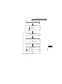
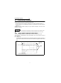
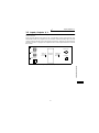
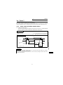
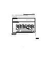
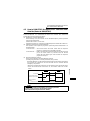
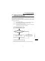
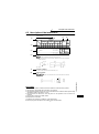
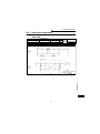
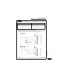
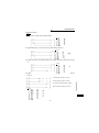
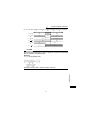
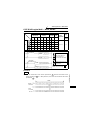
Fig 1.1 Operation Processings of Built-in PLC function
Sequence program operation processing
Step 0
to
Until execution of END instruction
Power on
I/O refresh processing
Initial processing
I/O initialization
Data memory initialization
Self-diagnostic checks
END processing
Self-diagnostic checks
Updating of timer and counter present values
and on/off of their contacts

4
RUN and STOP Operation Processings
1.2 RUN and STOP Operation Processings
The built-in PLC function has two different operation statuses: RUN status and STOP
status.
This section explains the operation processings of the built-in PLC function in each
operating status.
(1) Operation processing in RUN status
A RUN status indicates that a sequence program repeats its operation in order of
step 0 to END (FEND) instruction to step 0 when SQ-SD are shorted. (P.RUN is on)
When entering the RUN status, the function outputs the output status saved at STOP
according to the "STOP to (RUN-time output mode setting" (refer to page 41).
(2) Operation processing in STOP status
A STOP status indicates that a sequence program stops its operation when SQ-
SD are opened or remote STOP is commanded. (P.RUN is off)
When entering the STOP status, the function saves the output status and turns
off all outputs. The contents of the data memories other than the outputs (Y) are
maintained.
1.3 Program Makeup
(1) Program classification
The program that can be used by the built-in PLC function is a main sequence
program only. Microcomputer, interrupt and SFC programs cannot be used.
(2) Program capacity
A program capacity indicates the capacity of the program storage memory, and it
is 1k steps. Set the program capacity in the built-in PLC function parameter.
POINT
In either the RUN or STOP status, the built-in PLC function is performing I/O refresh
processings. In the STOP status, therefore, I/O monitoring and test operation can be
performed from the peripheral device.

5
Chapter 4
Chapter 3
Chapter 2
Chapter 1
Chapter 5
Chapter 6
Chapter 7
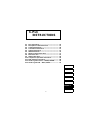
2. SEQUENCE PROGRAM
LANGUAGES AND
OPERATIONS
This chapter explains the programming languages and numerical
representations necessary for programming.
2.1 Programming Languages.................................... 6
2.2 Operation Processing Method of PLC Function
9
2.3 I/O Processing Method ........................................ 10
2.4 Scan Time.............................................................. 12
2.5 Numerical Values Usable in Sequence Program . 13

6
Programming Languages
2.1 Programming Languages
The built-in PLC function has two different programming methods: one that uses
ladders and the other that uses dedicated instructions.
• Programming that uses ladders is performed in the relay symbolic language. *1
• Programming that uses dedicated instructions is performed in the logic symbolic
language. *2
Whether the relay symbolic language or logic symbolic language is used, the same
program is created.
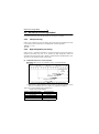
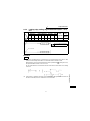
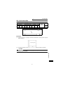
2.1.1 Relay symbolic language (Ladder mode)
The relay symbolic language is based on the concept of a relay control circuit.
You can perform programming in the representation close to the sequence circuit of
relay control.
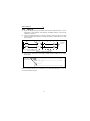
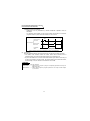
(1) Ladder block
A ladder block is the minimum unit for performing sequence program operation. It
starts with the left hand side vertical bus and ends with the right hand side vertical
bus.
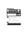
Fig 2.1 Ladder Blocks
REMARKS
*1. When using GX Developer for programming, perform programming in the "ladder mode".
*2. When using GX Developer for programming, perform programming in the "list mode".
Right hand
side vertical
bus
Ladder
blocks
Left hand side vertical bus
tep number
* X0 to X5: Indicate inputs.
Y10 to Y14: Indicate outputs.

7
Programming Languages
SEQUENCE PROGRAM LANGUAGES AND OPERATIONS
2
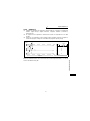
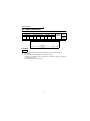
(2) Sequence program operation method
Sequence program operation repeats execution from a ladder block at step 0 to
an END instruction.
In a single ladder block, operation is performed from the left hand side vertical
bus to the right, and from the top to the bottom.
Fig 2.2 Operation Processing Sequence
Beginning of one
ladder block
Operation from left to right
End of one
ladder block
Operation from left to right
xecution
eturns to
tep 0 when
ND
nstruction is
xecuted.
1) to 17) indicate the sequence of program operation.
1)
2)
7) 8) 9)
10)
3) 4)
5)
6)
11) 13) 14)
12)
15)
16)
17)
Operation
from top
to bottom
Operation
from top
to bottom
END
End of one
ladder block
Beginning of
one ladder block

8
Programming Languages
2.1.2 Logic symbolic language (List mode)
The logic symbolic language uses dedicated instructions for programming contacts,
coils, etc. instead of their symbols used by the relay symbolic language.
(1) Program operation method
Sequence program operation is executed from an instruction at step 0 to an END
instruction in due order. When the END instruction is executed, operation is
executed from the instruction at step 0 again.
Fig 2.3 Operation Processing Sequence
Logic symbolic language Relay symbolic language
Step number
Operation
sequence
Execution returns to step 0
when END instruction is executed.
1)
1) 2) 7) 8) 9)
10)
3) 4)
5)
6)
11)
2)
3)
4)
5)
6)
7)
8)
9)
10)
11)

9
Operation Processing Method of PLC Function
SEQUENCE PROGRAM LANGUAGES AND OPERATIONS
2
2.2 Operation Processing Method of PLC Function
The operation processing method is the repeated operation of a stored program.
(1) Stored program system
1) In a stored program system, a sequence program to be operated is stored in
the internal memory beforehand.
2) When sequence program operation is executed, the sequence program stored
in the built-in PLC function is read to the CPU instruction by instruction to
execute the operation, and the corresponding devices are controlled according
to the results.
(2) Repeated operation system
In a repeated operation system, a sequence of operations is repeated.
The built-in PLC function repeats the following processings.
1) The built-in PLC function executes the sequence program stored in the
internal memory from step 0 in due order.
2)When the END instruction is executed, internal processings, such as timer/
counter present value updating and self-diagnostic checks, are performed, and
the execution returns to step 0 of the sequence program again.
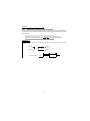
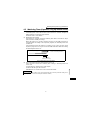
Fig 2.4 Operation Processing Method of Built-in PLC Function
REMARKS
A processing from step 0 to next step 0 or from END to next END is called one scan.
Therefore, one scan is the sum of the processing time of a user-created program (step 0 to
END) and the internal processing time of the built-in PLC function.
Step 0
Step 1
Step 2
END
Built-in sequence function repeats
this operation.
Timer/counter present
value updating
Self-diagnostic
checks, etc.

10
I/O Processing Method
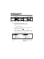
2.3 I/O Processing Method
The control system is a refresh system.
2.3.1 What is refresh system?
In the refresh system, control input terminal changes are batch-imported into the input
data memory of the CPU before execution of each scan, and the data of this input data
memory are used as the input data for operation execution.
Each program operation result of the output (Y) is output to the output data memory,
and after the END instruction is executed, the contents of the output data memory are
batch-output from the control output terminal.
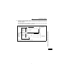
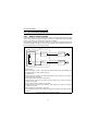
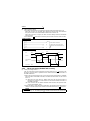
Fig 2.5 I/O Data Flows in Refresh System
• Input refresh
Before execution of step 0, input data are batch-read from the input module (1))
and stored into the input (X) data memory.
• Output refresh
Before execution of step 0, the data of the output (Y) data memory (2)) are batch-
output to the output module.
• When input contact instruction is executed
Input data are read from the input (X) data memory (3)) and the sequence
program is executed.
• When output contact instruction is executed
Output data are read from the output (Y) data memory (4)) and the sequence
program is executed.
• When output OUT instruction is executed
The operation result (5) of the sequence program is stored into the output (Y) data
memory.
CPU
(Central Processing Unit)
1)
2)
4)
5)
Y20
Y22
X0
3)
Input (X) data
memory
Output (Y)
data memory
Control input
terminal
At input refresh
Control output
terminal
At output refresh
PLC

11
I/O Processing Method
SEQUENCE PROGRAM LANGUAGES AND OPERATIONS
2
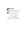
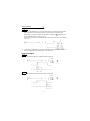
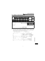
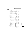
2.3.2 Response delay in refresh system
This section describes a delay of an output change in response to an input change.
An output change in response to an input change has a delay of up to two scans as
shown in Fig. 2.6.
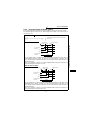
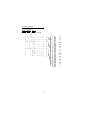
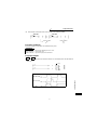
Fig 2.6 Output Y Change in Response to Input X Change
Ladder example
When Y1E turns on earliest
The Y1E output turns on earliest when the control input terminal turns from OFF to
ON immediately before a refresh. X5 turns on at an input refresh, Y1E turns on at
step 0, and the control output terminal turns on at an output refresh after execution of
the END instruction.
In this case, therefore, a delay of a control output terminal change in response to a
control input terminal change is one scan.
When Y1E turns on latest
The Y1E output turns on latest when the control input terminal turns from OFF to ON
immediately after a refresh. X5 turns on at the next input refresh, Y1E turns on at
step 0, and the control output terminal turns on at an output refresh after execution of
the END instruction.
In this case, therefore, a delay of a control output terminal change in response to a
control input terminal change is two scans.
In this ladder, output Y1E turns on when input
X5 turns on.
OFF
OFF
OFF
ON
ON
ON
OFF
ON
Input refresh Input refresh Output refresh
0
END END
056 0
(Minimum 1 scan)
Control output
terminal
Y1E
X5
Control input
terminal
Delay
OFF
OFF
OFF
ON
ON
ON
OFF
ON
Input refresh Input refresh Output refresh
0
END
END
056 0
Delay
(Maximum 2 scans)
Control output
terminal
Y1E
X5
Control input
terminal

12
Scan Time
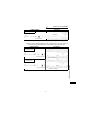
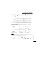
2.4 Scan Time
(1) Scan time
A scan time is a time from when sequence program operation is executed from
step 0 until step 0 is executed again.
The scan time of each scan is not equal, and changes depending on whether the
used instructions are executed or not.
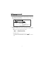
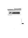
Fig 2.7 Scan Time
(2) Scan time confirmation
(a)The scan time from the END instruction to the next END instruction is timed in
the PLC, and stored into the special registers D9017 to D9019 in units of
10ms.
1) Data stored into special registers D9017 to D9019
• D9017............Minimum value of scan time
• D9018............Present value of scan time
• D9019............Maximum value of scan time
2) Scan time accuracy
The accuracy of the scan time observed in the PLC is 10ms.
For example, when the D9018 data is 5, the actual scan time is 40ms to
60ms.
Scan time
END END00
Sequence program
END processing
Timer/counter count processing
Self-diagnostic checks

13
Numerical Values Usable in Sequence Program
SEQUENCE PROGRAM LANGUAGES AND OPERATIONS
2
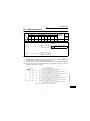
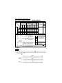
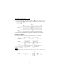
2.5 Numerical Values Usable in Sequence Program
The built-in PLC function represents numerical values, alphabets and other data in two
statuses: 0 (OFF) and 1 (ON).
The data represented by these 0s and 1s are called BIN (binary code).
The built-in PLC function can also use HEX (hexadecimal code) that represents BIN
data in blocks of four bits.
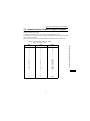
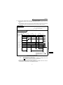
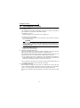
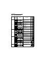
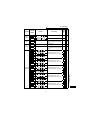
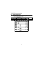
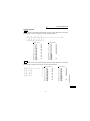
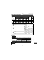
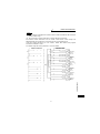
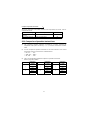
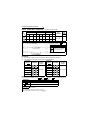
Table 2.1 indicates the numerical representations of BIN, HEX and decimal code.
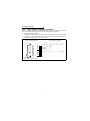
Table 2.1 Numerical Representations of BIN,
HEX and Decimal Code
DEC
(Decimal Code)
HEX
(Hexadecimal Code)
BIN
(Binary Code)
0
1
2
3
•
•
•
•
•
•
9
10
11
12
13
14
15
16
17
•
•
•
•
•
•
47
0
1
2
3
•
•
•
•
•
•
9
A
B
C
D
E
F
10
11
•
•
•
•
•
•
2F
0
1
10
11
•
•
•
•
•
•
1001
1010
1011
1100
1101
1110
1111
10000
10001
•
•
•
•
•
•
101111

14
Numerical Values Usable in Sequence Program
2.5.1 BIN (Binary Code)
(1) Binary code
BIN is a numerical value represented by 0s (OFF) and 1s (ON).
In the decimal code, a number is incremented from 0 to 9, and at this point, a
carry occurs and the number is incremented to 10.
In BIN, 0, 1 are followed by a carry, and the number is incremented to 10 (2 in
decimal).
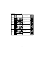
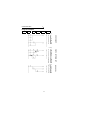
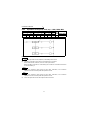
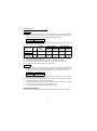
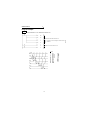
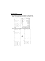
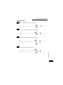
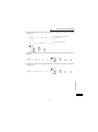
Table 2.2 indicates the numerical representations of BIN and decimal code.
Table 2.2 Differences between Numerical
Representations of BIN and Decimal Code
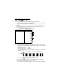
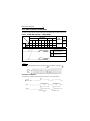
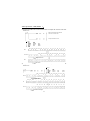
(2) Numerical representation of BIN
1)Each register (e.g. data register) of the built-in PLC function consist of 16 bits.
Each bit of the register is assigned a 2
n
value.
However, the most significant bit is used to judge whether the value is positive
or negative.
• Most significant bit is 0 ..... Positive
• Most significant bit is 1 ..... Negative
The numerical representation of each register of the built-in PLC function is
shown in Fig. 2.8.
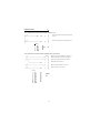
Fig 2.8 Numerical Representation of Each Register of Built-in PLC Function
2)Numerical data usable with the built-in PLC function
In the numerical representation shown in Fig. 2.8, values can be represented in
DEC (Decimal Code) BIN (Binary Code)
0 0000
1 0001
2 0010
3 0011
4 0100
5 0101
60110
7 0111
8 1000
9 1001
10 1010
11 1011
Carry
Carry
Carry
Value is negative if most significant bit is 1.
b15 b14 b13 b12 b11 b10 b9 b8 b7 b6 b5 b4 b3 b2 b1 b0
Most significant bit (for judgment of positive/negative)
2
14
2
13
2
12
2
11
2
10
2
9
2
8
2
7
2
6
2
5
2
4
2
3
2
2
2
1
2
0
2
15
16384
8192
4096 2048 1024
512 256 128 64 32 16 8 4 2 1
-32768
Bit name
ecimal value
=
=
=
=
=
=
=
=
=
=
=
=
=
=
=
=

15
Numerical Values Usable in Sequence Program
SEQUENCE PROGRAM LANGUAGES AND OPERATIONS
2
the range -32768 to 32767.
Therefore, each register of the built-in PLC function can store any value
between -32768 and 32767.
2.5.2 HEX (HEX Decimal)
(1) HEX
HEX represents four bits of BIN data as one digit.
Using four bits in BIN, you can represent 16 values from 0 to 15.
Since HEX represents any of 0 to 15 in a single digit, 9 is followed by alphabets A
(instead of 10), B (11)..., and F (15) is followed by a carry.
Refer to page 13 for the correspondences between BIN, HEX and decimal code.
(2) Numerical representation of HEX
Each register (e.g. data register) of the built-in PLC function consist of 16 bits.
Therefore, the value that can be stored into each register is represented as any of
0 to HFFFF in HEX.

16
MEMO
Page is loading ...
Page is loading ...
Page is loading ...
Page is loading ...
Page is loading ...
Page is loading ...
Page is loading ...
Page is loading ...
Page is loading ...
Page is loading ...
Page is loading ...
Page is loading ...
Page is loading ...
Page is loading ...
Page is loading ...
Page is loading ...
Page is loading ...
Page is loading ...
Page is loading ...
Page is loading ...
Page is loading ...
Page is loading ...
Page is loading ...
Page is loading ...
Page is loading ...
Page is loading ...
Page is loading ...
Page is loading ...
Page is loading ...
Page is loading ...
Page is loading ...
Page is loading ...
Page is loading ...
Page is loading ...
Page is loading ...
Page is loading ...
Page is loading ...
Page is loading ...
Page is loading ...
Page is loading ...
Page is loading ...
Page is loading ...
Page is loading ...
Page is loading ...
Page is loading ...
Page is loading ...
Page is loading ...
Page is loading ...
Page is loading ...
Page is loading ...
Page is loading ...
Page is loading ...
Page is loading ...
Page is loading ...
Page is loading ...
Page is loading ...
Page is loading ...
Page is loading ...
Page is loading ...
Page is loading ...
Page is loading ...
Page is loading ...
Page is loading ...
Page is loading ...
Page is loading ...
Page is loading ...
Page is loading ...
Page is loading ...
Page is loading ...
Page is loading ...
Page is loading ...
Page is loading ...
Page is loading ...
Page is loading ...
Page is loading ...
Page is loading ...
Page is loading ...
Page is loading ...
Page is loading ...
Page is loading ...
Page is loading ...
Page is loading ...
Page is loading ...
Page is loading ...
-
 1
1
-
 2
2
-
 3
3
-
 4
4
-
 5
5
-
 6
6
-
 7
7
-
 8
8
-
 9
9
-
 10
10
-
 11
11
-
 12
12
-
 13
13
-
 14
14
-
 15
15
-
 16
16
-
 17
17
-
 18
18
-
 19
19
-
 20
20
-
 21
21
-
 22
22
-
 23
23
-
 24
24
-
 25
25
-
 26
26
-
 27
27
-
 28
28
-
 29
29
-
 30
30
-
 31
31
-
 32
32
-
 33
33
-
 34
34
-
 35
35
-
 36
36
-
 37
37
-
 38
38
-
 39
39
-
 40
40
-
 41
41
-
 42
42
-
 43
43
-
 44
44
-
 45
45
-
 46
46
-
 47
47
-
 48
48
-
 49
49
-
 50
50
-
 51
51
-
 52
52
-
 53
53
-
 54
54
-
 55
55
-
 56
56
-
 57
57
-
 58
58
-
 59
59
-
 60
60
-
 61
61
-
 62
62
-
 63
63
-
 64
64
-
 65
65
-
 66
66
-
 67
67
-
 68
68
-
 69
69
-
 70
70
-
 71
71
-
 72
72
-
 73
73
-
 74
74
-
 75
75
-
 76
76
-
 77
77
-
 78
78
-
 79
79
-
 80
80
-
 81
81
-
 82
82
-
 83
83
-
 84
84
-
 85
85
-
 86
86
-
 87
87
-
 88
88
-
 89
89
-
 90
90
-
 91
91
-
 92
92
-
 93
93
-
 94
94
-
 95
95
-
 96
96
-
 97
97
-
 98
98
-
 99
99
-
 100
100
-
 101
101
-
 102
102
-
 103
103
-
 104
104


Mitsubishi Electric FR-C500 Programming Manual
- Type
- Programming Manual
Ask a question and I''ll find the answer in the document
Finding information in a document is now easier with AI
Related papers
-
Mitsubishi Electric FR-A700 User manual
-
-
-
-
-
-
-
-
-
Other documents
-
Contec PPC-SET Owner's manual
-
Omega EZPLC Series Owner's manual
-
Allen-Bradley MicroLogix 1000 User manual
-
-
Schneider Electric 372 SPU 780 01EMAN User manual
-
Eaton ELC-PB Programming Manual
-
-
-
Mitsubishi MELSEC System Q User manual
-
 Mitsubishi Electronics FX3U User manual
