Page is loading ...

RC420
Safety and Installation
Read this manual first
Rev.2 EM089B1740F

RC420 Safety and Installation Rev.2

RC420 Safety and Installation Rev.2 i
RC420 Safety and Installation
Rev.2
Copyright © 2007-2008 SEIKO EPSON CORPORATION. All rights reserved.

ii RC420 Safety and Installation Rev.2
FOREWORD
Thank you for purchasing our robot products.
This manual contains the information necessary for the correct use of the Operator
Panel.
Please carefully read this manual and other related manuals before installing the
robot system.
Keep this manual handy for easy access at all times.
WARRANTY
The robot system and its optional parts are shipped to our customers only after
being subjected to the strictest quality controls, tests, and inspections to certify its
compliance with our high performance standards.
Product malfunctions resulting from normal handling or operation will be repaired
free of charge during the normal warranty period. (Please ask your Regional Sales
Office for warranty period information.)
However, customers will be charged for repairs in the following cases (even if they
occur during the warranty period):
1. Damage or malfunction caused by improper use which is not described i
n
the manual, or careless use.
2. Malfunctions caused by customers’ unauthorized disassembly.
3. Damage due to improper adjustments or unauthorized repair attempts.
4. Damage caused by natural disasters such as earthquake, flood, etc.
Warnings, Cautions, Usage:
1. If the robot system associated equipment is used outside of the usage
conditions and product specifications described in the manuals, this
warranty is void.
2. If you do not follow the WARNINGS and CAUTIONS in this manual, we
cannot be responsible for any malfunction or accident, even if the result is
injury or death.
3. We cannot foresee all possible dangers and consequences. Therefore, this
manual cannot warn the user of all possible hazards.

RC420 Safety and Installation Rev.2 iii
TRADEMARKS
Microsoft, Windows, and Windows logo are either registered trademarks or
trademarks of Microsoft Corporation in the United States and/or other countries.
Other brand and product names are trademarks or registered trademarks of the
respective holders.
TRADEMARK NOTATION IN THIS MANUAL
Microsoft® Windows® XP Operating system
Microsoft® Windows® 2000 Operating system
Throughout this manual, Windows XP, and Windows 2000 refer to above
respective operating systems. In some cases, Windows refers generically to
Windows XP, and Windows 2000.
NOTICE
No part of this manual may be copied or reproduced without authorization.
The contents of this manual are subject to change without notice.
Please notify us if you should find any errors in this manual or if you have any
comments regarding its contents.
INQUIRIES
Contact the following service center for robot repairs, inspections or adjustments.
If service center information is not indicated below, please contact the supplier
office for your region.
Please prepare the following items before you contact us.
- Your controller model and its serial number
- Your manipulator model and its serial number
- Software and its version in your robot system
- A description of the problem
SERVICE CENTER

iv RC420 Safety and Installation Rev.2
MANUFACTURER & SUPPLIER
Japan & Others
SEIKO EPSON CORPORATION
Suwa Minami Plant
Factory Automation Systems Dept.
1010 Fujimi, Fujimi-machi,
Suwa-gun, Nagano, 399-0295
JAPAN
TEL : +81-(0)266-61-1802
FAX : +81-(0)266-61-1846
SUPPLIERS
North & South America
EPSON AMERICA, INC.
Factory Automation/Robotics
18300 Central Avenue
Carson, CA 90746
USA
TEL : +1-562-290-5900
FAX : +1-562-290-5999
Europe
EPSON DEUTSCHLAND GmbH
Factory Automation Division
Otto-Hahn-Str.4
D-40670 Meerbusch
Germany
TEL : +49-(0)-2159-538-1391
FAX : +49-(0)-2159-538-3170

RC420 Safety and Installation Rev.2 v
Before Reading This Manual
Do not connect the followings to OPTIONAL DEVICE Connector of RC420.
Connecting to the followings may result in malfunction of the device since the
pin assignments are different.
)
NOTE
Operator Panel OP1
Teach Pendant TP1
Teaching Pendant TP-3**
Operating Unit OPU-320
RC+ Software Key

vi RC420 Safety and Installation Rev.2
TABLE OF CONTENTS
1. Safety 1
1.1 Conventions································································ 1
1.2 Design and Installation Safety ···································· 2
1.3 Operation Safety························································· 3
1.4 Maintenance Safety ···················································· 5
1.5 Emergency Stop ························································· 8
1.6 Manipulator Labels ····················································· 9
1.7 Safety Features ························································ 10
2. Installation 15
Example ············································································ 15
2.1 Outline from Unpacking to Operation of Robot System
···················································································· 16 ·····
2.2 Unpacking································································· 17
2.3 Transportation··························································· 18
2.4 Manipulator Installation············································· 20
2.5 Controller Installation ················································ 23
2.6 Connecting Manipulator and Controller ···················· 24
2.7 Connecting Manipulator and Controller ···················· 33
2.8 Power-on ·································································· 35
3. First Step 37
3.1 Windows XP Setup ··················································· 37
3.2 UPS(uninterruptible power supply system) Setup····· 38
3.3 Installing EPSON RC+ Software······························· 39
3.4 Writing your first program·········································· 40
4. Second Step 44
4.1 Connection with External Equipment ························ 44
4.2 Connection and Display Language
tion OP500RC ························································· 45 of Op
5. Third Step 46
1. Safety
RC420 Safety and Installation Rev.2 1
1. Safety
Installation and transportation of robots and robotic equipment shall be performed
by qualified personnel and should conform to all national and local codes.
Please read this manual and other related manuals before installing the robot
system or before connecting cables.
Keep this manual handy for easy access at all times.
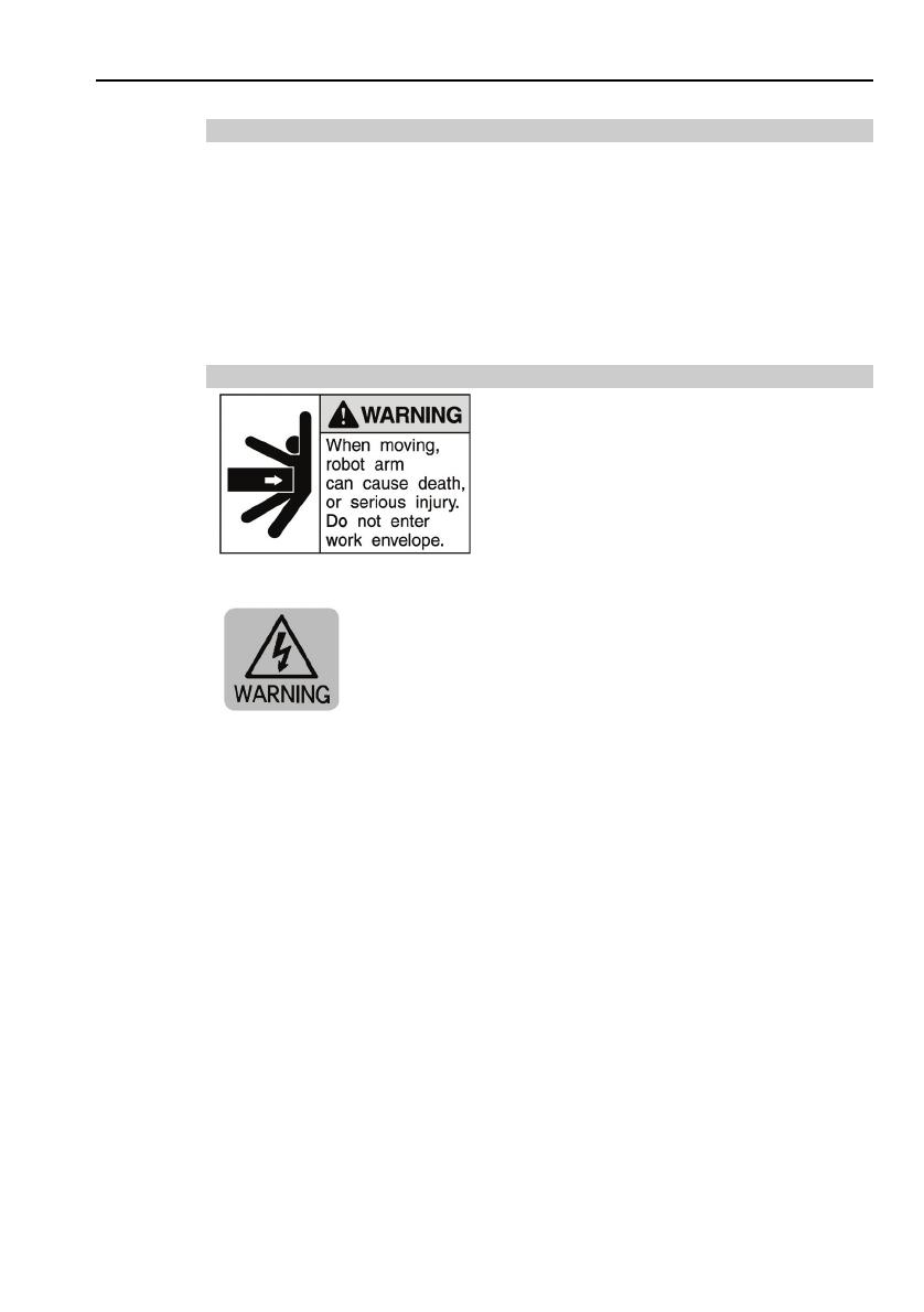
1.1 Conventions
Important safety considerations are indicated throughout the manual by the
following symbols. Be sure to read the descriptions shown with each symbol.
WARNING
This symbol indicates that a danger of possible serious injury
or death exists if the associated instructions are not followed
properly.
WARNING
This symbol indicates that a danger of possible harm to
people caused by electric shock exists if the associated
instructions are not followed properly.
CAUTION
This symbol indicates that a danger of possible harm to
people or physical damage to equipment and facilities exists
if the associated instructions are not followed properly.
1. Safety
1.2 Design and Installation Safety
Only trained personnel should design and install the robot system. Trained
personnel are defined as those who have taken robot system training held by the
manufacturer, dealer, or local representative company, or those who understand the
manuals thoroughly and have the same knowledge and skill level as those who
have completed the training courses.
To ensure safety, a safeguard must be installed for the robot system. For details
on the safeguard, refer to the Installation and Design Precautions in the Safety
chapter of the EPSON RC+ User’s Guide.
The following items are safety precautions for design personnel:
■
Personnel who design and/or construct the robot system with this
product must read the Safety chapter in the EPSON RC+ User’s
Guide to understand the safety requirements before designing and/or
constructing the robot system. Designing and/or constructing the
robot system without understanding the safety requirements is
extremely hazardous, and may result in serious bodily injury and/or
severe equipment damage to the robot system.
■
The Manipulator and the Controller must be used within the
environmental conditions described in their respective manuals. This
product has been designed and manufactured strictly for use in a
normal indoor environment. Using the product in an environment that
exceeds the specified environmental conditions may not only shorten
the life cycle of the product but may also cause serious safety
problems.
WARNING
■
The robot system must be used within the installation requirements
described in the manuals. Using the robot system outside of the
installation requirements may not only shorten the life cycle of the
product but also cause serious safety problems.
Further precautions for installation are mentioned in the following manuals.
Please read this chapter carefully to understand safe installation procedures before
installing the robots and robotic equipment.
Relevant Manuals
Refer
This manual : 2. Installation
Manipulator manual : Setup & Operation 3. Environment and Installation
2 RC420 Safety and Installation Rev.2

1. Safety
RC420 Safety and Installation Rev.2 3
1.3 Operation Safety
The following items are safety precautions for qualified Operator personnel:
■
Please carefully read the Safety-related Requirements in the Safety
chapter of the EPSON RC+ User’s Guide before operating the robot
system. Operating the robot system without understanding the safety
requirements is extremely hazardous and may result in serious bodily
injury and/or severe equipment damage to the robot system.
■
Do not enter the operating area of the Manipulator while the power to
the robot system is turned ON. Entering the operating area with the
power ON is extremely hazardous and may cause serious safety
problems as the Manipulator may move even if it seems to be stopped.
■
Before operating the robot system, make sure that no one is inside the
safeguarded area. The robot system can be operated in the mode for
teaching even when someone is inside the safeguarded area.
The motion of the Manipulator is always in restricted status (low
speeds and low power) to secure the safety of an operator. However,
operating the robot system while someone is inside the safeguarded
area is extremely hazardous and may result in serious safety problems
in case that the Manipulator moves unexpectedly.
WARNING
■
Immediately press the Emergency Stop switch whenever the
Manipulator moves abnormally while the robot system is operated.
Continuing the operating the robot system while the Manipulator
moves abnormally is extremely hazardous and may result in serious
bodily injury and/or severe equipment change to the robot system.
WARNING
■
Be sure to connect the AC power cable to a power receptacle. DO
NOT connect it directly to a factory power source. To shut off power
to the robot system, pull out the power plug from the power source.
Performing any work while connecting the AC power cable to a factory
power source is extremely hazardous and may result in electric shock
and/or malfunction of the robot system.
1. Safety
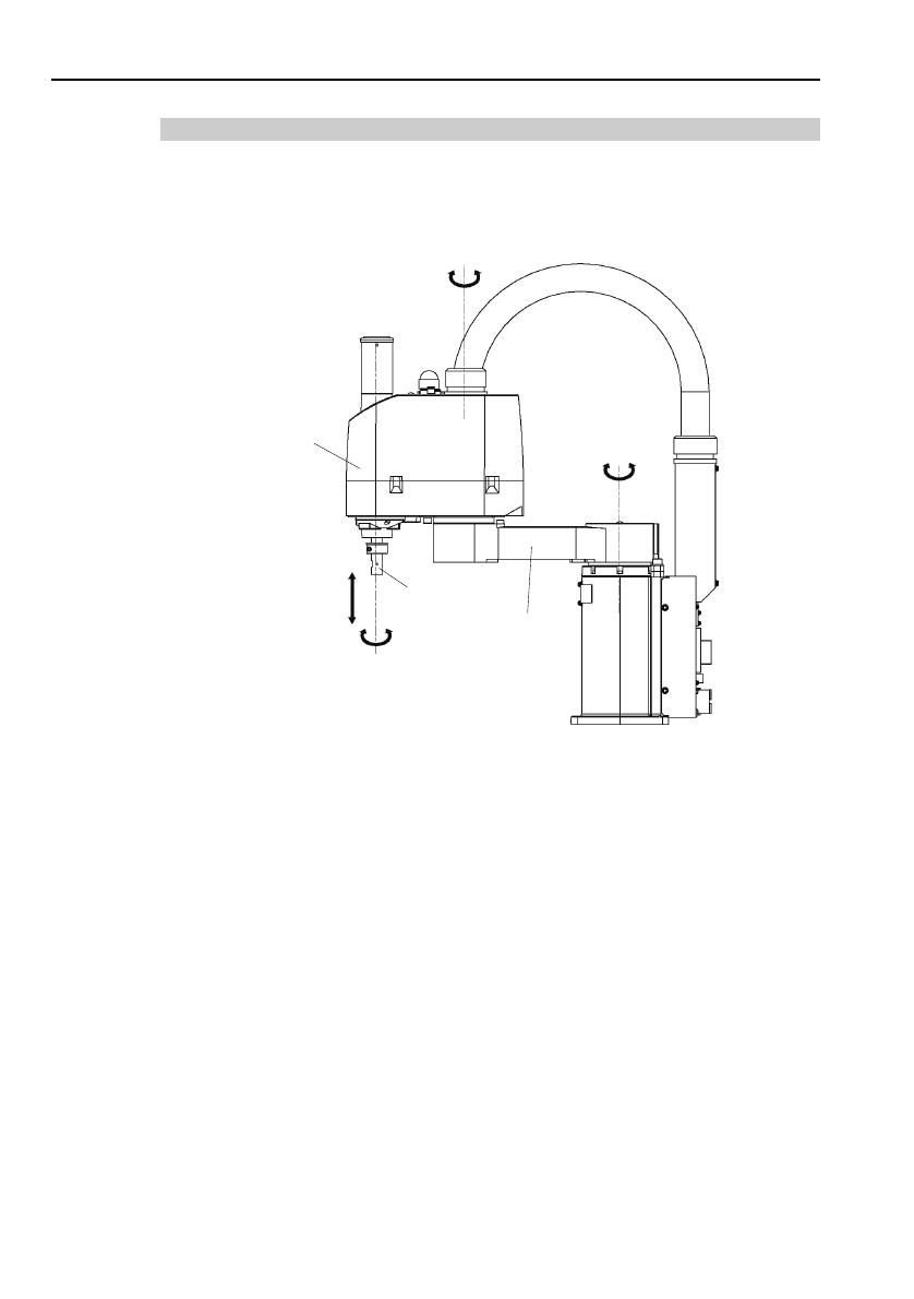
Part Names and Arm Motion
The motion range of each arm is shown in the figure below. Take all
necessary safety precautions.
Joint #3
(Up/Down)
Joint #4
(Rotate)
A
rm #1
Arm #2
+
-
Shaft
(Figure of E2C)
Joint #2
(Rotate)
+
−
Joint #1
(Rotate)
+
-
+
-
4 RC420 Safety and Installation Rev.2

1. Safety
RC420 Safety and Installation Rev.2 5
1.4 Maintenance Safety
Please read this section, Maintenance of the Manipulator manual, and other related
manuals carefully to understand safe maintenance procedures before performing
any maintenance.
Only authorized personnel who have taken the safety training should be allowed to
maintain the robot system. The safety training is the program for the industrial
robot operator that follows the laws and regulations of each nation.
The personnel who have taken the safety training acquire knowledge of industrial
robots (operations, teaching, etc.), knowledge of inspections, and knowledge of
related rules/regulations. Only personnel who have completed the robot
system-training and maintenance-training classes held by the manufacturer, dealer,
or locally-incorporated company should be allowed to maintain the robot system.
■
Do not remove any parts that are not covered in this manual. Follow
the maintenance procedure strictly as described in this manual and the
Maintenance of the Manipulator manual. Improper removal of parts
or improper maintenance may not only cause improper function of the
robot system but also serious safety problems.
■
Keep away from the Manipulator while the power is ON if you have not
taken the training courses. Do not enter the operating area while the
power is ON. Entering the operating area with the power ON is
extremely hazardous and may cause serious safety problems as the
Manipulator may move even though it seems to be stopped.
■
When you check the operation of the Manipulator after replacing parts,
be sure to check it while you are outside of the safeguarded area.
Checking the operation of the Manipulator while you are inside of the
safeguarded area may cause serious safety problems as the
Manipulator may move unexpectedly.
WARNING
■
Before operating the robot system, make sure that both the
Emergency Stop switches and safeguard switches function properly.
Operating the robot system when the switches do not function properly
is extremely hazardous and may result in serious bodily injury and/or
serious damage to the robot system as the switches cannot fulfill their
intended functions in an emergency.
1. Safety
6 RC420 Safety and Installation Rev.2
■
Be sure to connect the AC power cable to a power receptacle. DO
NOT connect it directly to a factory power source. To shut off power to
the robot system, pull out the power plug from the power source.
Performing any work while connecting the AC power cable to a factory
power source is extremely hazardous and may result in electric shock
and/or malfunction of the robot system.
■
Before performing any replacement procedure, turn OFF the Controller
and related equipment, and then pull out the power plug from the power
source.
Performing any replacement procedure with the power ON is extremely
hazardous and may result in electric shock and/or malfunction of the
robot system.
WARNING
■
Be sure to connect the cables properly. Do not allow unnecessary
strain on the cables. (Do not put heavy objects on the cables. Do not
bend or pull the cables forcibly.) The unnecessary strain on the cables
may result in damage to the cables, disconnection, and/or contact
failure. Damaged cables, disconnection, or contact failure is extremely
hazardous and may result in electric shock and/or improper function of
the robot system.
CAUTION
■
Carefully use alcohol, liquid gasket, and adhesive following respective
instructions and also instructions below. Careless use of alcohol, liquid
gasket, or adhesive may cause a fire and/or safety problems.
- Never put alcohol, liquid gasket, or adhesive close to fire.
- Use alcohol, liquid gasket, or adhesive while ventilating the room.
- Wear protective gear including a mask, protective goggles, and
oil-resistant gloves.
- If alcohol, liquid gasket, or adhesive gets on your skin, wash the area
thoroughly with soap and water.
- If alcohol, liquid gasket, or adhesive gets into your eyes or mouth,
flush your eyes or wash out your mouth with clean water thoroughly,
and then see a doctor immediately.

1. Safety
RC420 Safety and Installation Rev.2 7
CAUTION
■
Wear protective gear including a mask, protective goggles, and
oil-resistant gloves during grease up. If grease gets into your eyes,
mouth, or on your skin, follow the instructions below.
If grease gets into your eyes :
Flush them thoroughly with clean water, and then see a doctor
immediately.
If grease gets into your mouth:
If swallowed, do not induce vomiting. See a doctor immediately.
If grease just gets into your mouth, wash out your mouth with
water thoroughly.
If grease gets on your skin:
Wash the area thoroughly with soap and water.

1. Safety
8 RC420 Safety and Installation Rev.2
1.5 Emergency Stop
If the Manipulator moves abnormally during operation, immediately press the
Emergency Stop switch. The motor power will be turned OFF, and the arm
motion by inertia will be stopped with the electromagnetic brake and dynamic
brake.
However, avoid pressing the Emergency Stop switch unnecessarily while the
Manipulator is running normally. Otherwise, the Manipulator may hit the
peripheral equipment since the operating trajectory while the robot system stops is
different from that in normal operation.
To place the robot system in emergency mode during normal operation, press the
Emergency Stop switch when the Manipulator is not moving.
Refer to the Controller manual for instructions on how to wire the Emergency Stop
switch circuit.
Free running distance in emergency
The operating Manipulator cannot stop immediately after the Emergency Stop
switch is pressed.
Remember that the values vary depending on conditions such as the weight of the
end effector and work piece, Weight/Speed/Accel settings, operating pose, etc.
1. Safety
RC420 Safety and Installation Rev.2 9
1.6 Manipulator Labels
Labels are attached around the locations of the Manipulator where specific dangers
exist.
Be sure to comply with descriptions and warnings on the labels to operate and
maintain the Manipulator safely.
Do not tear, damage, or remove the labels. Use meticulous care when handling
those parts or units to which the following labels are attached as well as the nearby
areas:
Examples of Manipulator Labels
NOTE:
Hazardous voltage exists while the
Manipulator is ON. To avoid electric
shock, do not touch any internal
electric parts.

1. Safety
10 RC420 Safety and Installation Rev.2
1.7 Safety Features
The robot control system supports safety features described below. However, the
user is recommended to strictly follow the proper usage of the robot system by
thoroughly reading the attached manuals before using the system. Failure to read
and understand the proper usage of the safety functions is highly dangerous.
Among the following safety features, the Emergency Stop Switch and Safety Door
Input are particularly important. Make sure that these and other features function
properly before operating the robot system.
For details, refer to the 2.5 Controller Installation - Safety Door Switch and Latch
Release Switch.
ATTEND (TEACH) Control Device
To operate the Manipulator at a short distance without any operation unit (option),
you must create an ATTEND (TEACH) control device and connect it to the
OPTIONAL DEVICE connector on the front of the Control Unit in order to
operate the Manipulator at a short distance. The ATTEND (TEACH) control
device should consist of the Emergency Stop switch, 3-position enable switch
(dead-man switch), and ATTEND (TEACH) control device enable/disable switch.
The name of the control device depends on the software used in your Control Unit
as shown below:
EPSON RC+ : TEACH control device
SPEL CT : ATTEND control device
Emergency Stop Switch
The ATTEND (TEACH) control device must be equipped with the Emergency
Stop switch. The EMERGENCY connector on the Drive Unit has extension
Emergency Stop input terminals used for connecting the Emergency Stop switches.
These Emergency Stop inputs are internally connected to the relays for the
dynamic brake. Therefore, pressing any Emergency Stop switch can shut off the
motor power immediately and the robot system will enter the Emergency Stop
condition.

1. Safety
RC420 Safety and Installation Rev.2 11
Safety Door Input
In order to activate this feature, make sure that the Safety Door Input switch is
connected to the EMERGENCY connector on the Drive Unit.
When the safety door is opened, normally the Manipulator immediately stops the
current operation, and the status of Manipulator power is operation-prohibited
until the safety door is closed and the latched condition is released. In order to
execute the Manipulator operation while the safety door is open, you must change
the ATTEND (TEACH) control device enable/disable switch to “enable” or
change the mode selector switch on the operation unit to the mode for teaching and
then engage the 3-position enable switch. In this case, the Manipulator is
operated in low power status.
Lockout
Turn OFF the power supply and use a lockout procedure to prevent anyone from
turning ON the power supply by mistake while someone else is in the safeguarded
area for maintenance or repairs.
The procedure for lockout is described in the Maintenance 1. Safety Precautions
for Maintenance.
Low Power Mode
The motor power is reduced in this mode. A shift into restricted status (low
power status) can be done through the execution of a power status change
instruction, regardless of the safety door or operation mode. This ensures the
safety of the operator and reduces the possibility of peripheral equipment being
destroyed or damaged as a result of careless operation.
Dynamic Brake
The dynamic brake circuit includes relays that short the motor armatures. When
the motor armatures are shorted, the power to the Motor Driver modules is cut off
and the reverse EMF caused by the short stops the motors. The dynamic brake
circuit is activated when there is an Emergency Stop input or when any of the
following errors is detected: encoder cable disconnection, motor overload,
irregular motor torque, motor speed error, servo error (positioning or speed
overflow), irregular CPU, memory check-sum error and overheat condition inside
the Motor Driver Module.

1. Safety
12 RC420 Safety and Installation Rev.2
Encoder Cable Disconnection Error Detection
The dynamic brake circuit is activated when the Motor Encoder Signal cable
(connecting to the Drive Unit) is disconnected.
Motor Overload Detection
The dynamic brake circuit is activated when the system detects that the load on the
motor has exceeded its capacity.
Irregular Motor Torque (out-of-control manipulator) Detection
The dynamic brake circuit is activated when irregularity with motor torque (motor
output) is detected (in which case the Manipulator is out of control).
Motor Speed Error Detection
The dynamic brake circuit is activated when the system detects that the motor is
running at incorrect speed.
Positioning Overflow - Servo Error - Detection
The dynamic brake circuit is activated when the system detects that the difference
between the Manipulator’s actual position and commanded position exceeds the
margin of error allowed.
Speed Overflow - Servo Error - Detection
The dynamic brake circuit is activated when the system detects that motor speed
has overflowed.
CPU Irregularity Detection
Irregularity in the motor controlling CPU is monitored by a watch-dog timer.
Also, the system CPU inside the Control Unit and the motor controlling CPU
inside the Drive Unit are designed to constantly check each other for any
discrepancies between the units. If a discrepancy is detected, the dynamic brake
circuit is activated.
Memory Check-sum Error Detection
The dynamic brake circuit is activated when a memory check-sum error is
detected.
/
