
Motoman, Incorporated
805 Liberty Lane
West Carrollton, OH 45449
TEL: (937) 847-6200
FAX: (937) 847-6277
24-Hour Service Hotline: (937) 847-3200
Motoman NX100 Controller
DA20C
Manipulator Manual
Part Number: 151528-1CD
Revision 0

The information contained within this document is the proprietary property of Motoman, Inc., and may not be
copied, reproduced or transmitted to other parties without the expressed written authorization of Motoman,
Inc.
©2007 by MOTOMAN
All Rights Reserved
Because we are constantly improving our products, we reserve the right to change specifications without
notice. MOTOMAN is a registered trademark of YASKAWA Electric Manufacturing.
COMPLETE OUR ONLINE SURVEY
Motoman is committed to total customer satisfaction! Please give us your feedback on the technical manuals you
received with your Motoman robotic solution.
To participate, go to the following website:
http://www.motoman.com/forms/techpubs.asp

DA20C
151528-1
Final page 1
Chapter 1
Introduction
1.1 About This Document
This manual provides information for the DA20C Manipulator and contains the following sections:
CHAPTER 1 - INTRODUCTION
Provides general information about the structure of this manual, a list of reference documents, and
customer service information.
CHAPTER 2 - SAFETY
This section provides information regarding the safe use and operation of Motoman products.
CHAPTER 3 - DA20C INSTRUCTIONS
Provides detailed information for the DA20C Manipulator.
1.2 Reference to Other Documentation
For additional information refer to the following:
• NX100 Controller Manual (P/N 149201-1)
• Concurrent I/O Manual (P/N 149230-1)
• Operator’s Manual for your application
• Vendor manuals for system components not manufactured by Motoman
1.3 Customer Service Information
If you are in need of technical assistance, contact the Motoman service staff at (937) 847-3200. Please have
the following information ready before you call:
• Robot Type (DA20C, HP50, etc.)
• Application Type (handling, welding, etc.)
• Robot Serial Number (located on back side of robot arm)
• Robot Sales Order Number (located on back of controller)

Manipulator Manual
Chapter 1 Introduction
page 2 Final
Notes

DA20C
151528-1
Final page 3
Chapter 2
Safety
2.1 Introduction
It is the purchaser’s responsibility to ensure that all local, county, state,
and national codes, regulations, rules, or laws relating to safety and safe
operating conditions for each installation are met and followed.
We suggest that you obtain and review a copy of the ANSI/RIA National Safety Standard for
Industrial Robots and Robot Systems. This information can be obtained from the Robotic Industries
Association by requesting ANSI/RIA R15.06-1999. The address is as follows:
Robotic Industries Association
900 Victors Way
P.O. Box 3724
Ann Arbor, Michigan 48106
TEL: (734) 994-6088
FAX: (734) 994-3338
INTERNET: www.roboticsonline.com
Ultimately, the best safeguard is trained personnel. The user is responsible for providing personnel
who are adequately trained to operate, program, and maintain the robot cell. The robot must not be
operated by personnel who have not been trained!
We recommend that all personnel who intend to operate, program, repair, or use the robot system be
trained in an approved Motoman training course and become familiar with the proper operation of the
system.

Manipulator Manual
Chapter 2 Safety
page 4 Final
This safety section addresses the following:
• Standard Conventions (Section 2.2)
• General Safeguarding Tips (Section 2.3)
• Mechanical Safety Devices (Section 2.4)
• Installation Safety (Section 2.5)
• Programming, Operation, and Maintenance Safety (Section 2.6)
2.2 Standard Conventions
This manual includes the following alerts – in descending order of severity – that are essential to the
safety of personnel and equipment. As you read this manual, pay close attention to these alerts to
insure safety when installing, operating, programming, and maintaining this equipment.
DANGER!
Information appearing in a DANGER concerns the protection of personnel from the immediate
and imminent hazards that, if not avoided, will result in immediate, serious personal injury or
loss of life in addition to equipment damage.
WARNING!
Information appearing in a WARNING concerns the protection of personnel and equipment from
potential hazards that can result in personal injury or loss of life in addition to equipment
damage.
CAUTION!
Information appearing in a CAUTION concerns the protection of personnel and equipment,
software, and data from hazards that can result in minor personal injury or equipment damage.
Note: Information appearing in a Note provides additional information which is helpful in understanding the item being
explained.

DA20C
151528-1
Final page 5
2.3 General Safeguarding Tips
All operators, programmers, plant and tooling engineers, maintenance personnel, supervisors, and
anyone working near the robot must become familiar with the operation of this equipment. All
personnel involved with the operation of the equipment must understand potential dangers of
operation. General safeguarding tips are as follows:
• Improper operation can result in personal injury and/or damage to the equipment. Only
trained personnel familiar with the operation of this robot, the operator's manuals, the system
equipment, and options and accessories should be permitted to operate this robot system.
• Do not enter the robot cell while it is in automatic operation. Programmers must have the
teach pendant when they enter the robot cell.
• Improper connections can damage the robot. All connections must be made within the
standard voltage and current ratings of the robot I/O (Inputs and Outputs).
• The robot must be placed in Emergency Stop (E-STOP) mode whenever it is not in use.
• In accordance with ANSI/RIA R15.06-1999, section 4.2.5, Sources of Energy, use
lockout/tagout procedures during equipment maintenance. Refer also to Section 1910.147
(29CFR, Part 1910), Occupational Safety and Health Standards for General Industry
(OSHA).
2.4 Mechanical Safety Devices
The safe operation of the robot, positioner, auxiliary equipment, and system is ultimately the user's
responsibility. The conditions under which the equipment will be operated safely should be reviewed
by the user. The user must be aware of the various national codes, ANSI/RIA R15.06-1999 safety
standards, and other local codes that may pertain to the installation and use of industrial equipment.
Additional safety measures for personnel and equipment may be required depending on system
installation, operation, and/or location. The following safety equipment is provided as standard:
• Safety fences and barriers
• Light curtains and/or safety mats
• Door interlocks
• Emergency stop palm buttons located on operator station, robot controller, and
programming pendant
Check all safety equipment frequently for proper operation. Repair or replace any non-functioning
safety equipment immediately.

Manipulator Manual
Chapter 2 Safety
page 6 Final
2.5 Installation Safety
Safe installation is essential for protection of people and equipment. The following suggestions are
intended to supplement, but not replace, existing federal, local, and state laws and regulations.
Additional safety measures for personnel and equipment may be required depending on system
installation, operation, and/or location. Installation tips are as follows:
• Be sure that only qualified personnel familiar with national codes, local codes, and
ANSI/RIA R15.06-1999 safety standards are permitted to install the equipment.
• Identify the work envelope of each robot with floor markings, signs, and barriers.
• Position all controllers outside the robot work envelope.
• Whenever possible, install safety fences to protect against unauthorized entry into the work
envelope.
• Eliminate areas where personnel might get trapped between a moving robot and other
equipment (pinch points).
• Provide sufficient room inside the workcell to permit safe teaching and maintenance
procedures.
2.6 Programming, Operation, and Maintenance Safety
All operators, programmers, plant and tooling engineers, maintenance personnel, supervisors, and
anyone working near the robot must become familiar with the operation of this equipment. Improper
operation can result in personal injury and/or damage to the equipment. Only trained personnel
familiar with the operation, manuals, electrical design, and equipment interconnections of this robot
should be permitted to program, operate, and maintain the system. All personnel involved with the
operation of the equipment must understand potential dangers of operation.
• Inspect the robot and work envelope to be sure no potentially hazardous conditions exist. Be
sure the area is clean and free of water, oil, debris, etc.
• Be sure that all safeguards are in place. Check all safety equipment for proper operation.
Repair or replace any non-functioning safety equipment immediately.
• Do not enter the robot cell while it is in automatic operation. Be sure that only the person
holding the programming pendant enters the workcell.
• Check the E-STOP button on the programming pendant for proper operation before
programming. The robot must be placed in Emergency Stop (E-STOP) mode whenever it is
not in use.
• Back up all programs and jobs onto suitable media before program changes are made. To
avoid loss of information, programs, or jobs, a backup must always be made before any
service procedures are done and before any changes are made to options, accessories, or
equipment.

DA20C
151528-1
Final page 7
• Any modifications to PART 1, System Section, of the robot controller concurrent I/O
program can cause severe personal injury or death, as well as damage to the robot! Do not
make any modifications to PART 1, System Section. Making any changes without the written
permission of Motoman will VOID YOUR WARRANTY!
• Some operations require standard passwords and some require special passwords. Special
passwords are for Motoman use only. YOUR WARRANTY WILL BE VOID if you use
these special passwords.
• The robot controller allows modifications of PART 2, User Section, of the concurrent I/O
program and modifications to controller parameters for maximum robot performance. Great
care must be taken when making these modifications. All modifications made to the
controller will change the way the robot operates and can cause severe personal injury or
death, as well as damage the robot and other parts of the system. Double-check all
modifications under every mode of robot operation to ensure that you have not created
hazards or dangerous situations.
• Check and test any new or modified program at low speed for at least one full cycle.
• This equipment has multiple sources of electrical supply. Electrical interconnections are
made between the controller and other equipment. Disconnect and lockout/tagout all
electrical circuits before making any modifications or connections.
• Do not perform any maintenance procedures before reading and understanding the proper
procedures in the appropriate manual.
• Use proper replacement parts.
• Improper connections can damage the robot. All connections must be made within the
standard voltage and current ratings of the robot I/O (Inputs and Outputs).

Manipulator Manual
Chapter 2 Safety
page 8 Final
Notes

YASKAWA
YASKAWA MANUAL NO.
HW0483402
MOTOMAN-DA20
INSTRUCTIONS
TYPE: YR-DA20-A00 (STANDARD SPECIFICATION)
Upon receipt of the product and prior to initial operation, read these instructions thoroughly, and retain
for future reference.
MOTOMAN INSTRUCTIONS
MOTOMAN-DA20 INSTRUCTIONS
NX100 INSTRUCTIONS
NX100 OPERATOR’S MANUAL
NX100 MAINTENACE MANUAL
The NX100 operator’s manual above corresponds to specific usage.
Be sure to use the appropriate manual.
1/59

ii
HW0483402
HW0483402
• This instruction manual explains operating instructions and mainte-
nance procedures primarily for MOTOMAN-DA20.
• General items related to safety are listed in Section 1: Safety of the
NX100 Instructions. To ensure correct and safe operation, carefully
read the NX100 instructions before reading this manual.
• Some drawings in this manual are shown with the protective covers or
shields removed for clarity. Be sure all covers and shields are replaced
before operating this product.
• The drawings and photos in this manual are representative examples
and differences may exist between them and the delivered product.
• YASKAWA may modify this model without notice when necessary due to
product improvements, modifications, or changes in specifications. If
such modification is made, the manual number will also be revised.
• If your copy of the manual is damaged or lost, contact a YASKAWA rep-
resentative to order a new copy. The representatives are listed on the
back cover. Be sure to tell the representative the manual number listed
on the front cover.
• YASKAWA is not responsible for incidents arising from unauthorized
modification of its products. Unauthorized modification voids your prod-
uct’s warranty.
MANDATORY
CAUTION
2/59

iii
HW0483402
HW0483402
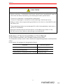
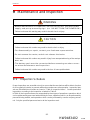
Notes for Safe Operation
Read this manual carefully before installation, operation, maintenance, or inspection of the
NX100.
In this manual, the Notes for Safe Operation are classified as “WARNING”, “CAUTION”,
“MANDATORY”, or “PROHIBITED”.
Even items described as “CAUTION” may result in a serious accident in some situations. At
any rate, be sure to follow these important items.
Indicates a potentially hazardous situation which, if not avoided,
could result in death or serious injury to personnel.
Indicates a potentially hazardous situation which, if not avoided,
could result in minor or moderate injury to personnel and dam-
age to equipment. It may also be used to alert against unsafe
practices.
Always be sure to follow explicitly the items listed under this
heading.
Must never be performed.
To ensure safe and efficient operation at all times, be sure to follow all instructions, even if
not designated as “CAUTION” and “WARNING”.
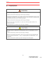
WARNING
CAUTION
MANDATORY
PROHIBITED
NOTE
3/59

iv
HW0483402
HW0483402
• Before operating the manipulator, check that servo power is turned OFF
when the emergency stop buttons on the front door of the NX100 and
programming pendant are pressed.
When the servo power is turned OFF, the SERVO ON LED on the program-
ming pendant is turned OFF.
Injury or damage to machinery may result if the emergency stop circuit cannot stop the
manipulator during an emergency. The manipulator should not be used if the emergency
stop buttons do not function.
Emergency Stop Button
• Once the emergency stop button is released, clear the cell of all items
which could interfere with the operation of the manipulator. Then turn
ON the servo power.
Injury may result from unintentional or unexpected manipulator motion.
Release of Emergency Stop
• Observe the following precautions when performing teaching operations
within the working envelope of the manipulator:
- View the manipulator from the front whenever possible.
- Always follow the predetermined operating procedure.
- Ensure that you have a safe place to retreat in case of emergency.
Improper or unintended manipulator operation may result in injury.
• Confirm that no persons are present in the manipulator’s work envelope
and that you are in a safe location before:
- Turning ON the NX100 power.
- Moving the manipulator with the programming pendant.
- Running check operations.
- Performing automatic operations.
Injury may result if anyone enters the working envelope of the manipulator during opera-
tion. Always press an emergency stop button immediately if there is a problem. The
emergency stop button is located on the right of the front door of the NX100 and the pro-
gramming pendant.
WARNING
TURN
4/59

v
HW0483402
HW0483402
Definition of Terms Used Often in This Manual
The MOTOMAN manipulator is the YASKAWA industrial robot product.
The manipulator usually consists of the controller, the programming pendant, and manipulator
cables.
In this manual, the equipment is designated as follows:
• Perform the following inspection procedures prior to conducting manip-
ulator teaching. If problems are found, repair them immediately, and be
sure that all other necessary processing has been performed.
-Check for problems in manipulator movement.
-Check for damage to insulation and sheathing of external wires.
• Always return the programming pendant to the hook on the NX100 cabi-
net after use.
The programming pendant can be damaged if it is left in the manipulator’s work area, on
the floor, or near fixtures.
• Read and understand the Explanation of the Warning Labels in the
NX100 instructions before operating the manipulator.
Equipment Manual Designation
NX100 controller NX100
NX100 programming pendant Programming pendant
Cable between the manipulator and the controller Manipulator cable
CAUTION
5/59

vi
HW0483402
HW0483402
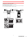
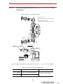
Explanation of Warning Labels
The following warning labels are attached to the manipulator.
Always follow the warnings on the labels.
Also, an identification label with important information is placed on the body of the manipula-
tor. Prior to operating the manipulator, confirm the contents.
MOTOMAN
TYPE
PAYLOAD
ORDER NO.
SERIAL NO.
MASS
DATE
YASKAWA ELECTRIC CORPORAION JAPAN
kg
kg
Warning Label A:
Warning Label B:
Nameplate:
Warning label A
Warning label B Nameplate
Warning label A
Warning label B
WARNING
Do not enter
robot
work area.
WARNING
Moving parts
may cause
injury
6/59

vii
HW0483402
HW0483402
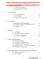
1 Product Confirmation
1.1 Contents Confirmation. . . . . . . . . . . . . . . . . . . . . . . . . . . . . 1-1
1.2 Order Number Confirmation . . . . . . . . . . . . . . . . . . . . . . . 1-2
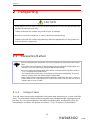
2 Transporting
2.1 Transporting Method . . . . . . . . . . . . . . . . . . . . . . . . . . . . . . 2-1
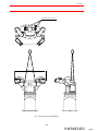
2.1.1 Using a Crane . . . . . . . . . . . . . . . . . . . . . . . . . . . . . . . . . . . . . .2-1
2.1.2 Using a Forklift. . . . . . . . . . . . . . . . . . . . . . . . . . . . . . . . . . . . . .2-3
2.2 Shipping Bolts and Brackets. . . . . . . . . . . . . . . . . . . . . . . 2-4
3 Installation
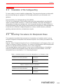
3.1 Installation of the Safeguarding . . . . . . . . . . . . . . . . . . . . 3-2
3.2 Mounting Procedures for Manipulator Base . . . . . . . . 3-2
3.2.1 Mounting Example. . . . . . . . . . . . . . . . . . . . . . . . . . . . . . . . . . .3-3
3.3 Location. . . . . . . . . . . . . . . . . . . . . . . . . . . . . . . . . . . . . . . . . . . 3-3
4 Wiring4.1 Grounding. . . . . . . . . . . . . . . . . . . . . . . . . . . . . . . . . . . . . . . . . 4-1
4.2 Manipulator Cable Connection. . . . . . . . . . . . . . . . . . . . . 4-2
4.2.1 Connection to the Manipulator. . . . . . . . . . . . . . . . . . . . . . . . . .4-2
4.2.2 Connection to the NX100 . . . . . . . . . . . . . . . . . . . . . . . . . . . . .4-2
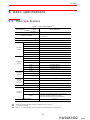
5 Basic Specifications
5.1 Basic Specifications . . . . . . . . . . . . . . . . . . . . . . . . . . . . . . . 5-1
5.2 Part Names and Working Axes . . . . . . . . . . . . . . . . . . . . 5-2
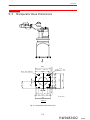
5.3 Manipulator Base Dimensions . . . . . . . . . . . . . . . . . . . . . 5-3
5.4 Dimensions and P-Point Maximum Envelope . . . . . . 5-4
5.5 Alterable Operating Range . . . . . . . . . . . . . . . . . . . . . . . . 5-5
6 Allowable Load for Wrist Axis and Wrist Flange
6.1 Allowable Wrist Load . . . . . . . . . . . . . . . . . . . . . . . . . . . . . . 6-1
6.2 Wrist Flange. . . . . . . . . . . . . . . . . . . . . . . . . . . . . . . . . . . . . . . 6-2
7/59

viii
HW0483402
HW0483402
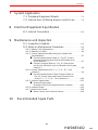
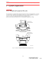
7 System Application
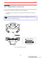
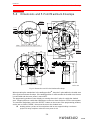
7.1 Peripheral Equipment Mounts . . . . . . . . . . . . . . . . . . . . . .7-1
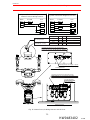
7.2 Internal User I/O Wiring Harness and Air Line . . . . . .7-2
8 Electrical Equipment Specification
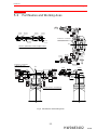
8.1 Internal Connections . . . . . . . . . . . . . . . . . . . . . . . . . . . . . . .8-1
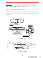
9 Maintenance and Inspection
9.1 Inspection Schedule. . . . . . . . . . . . . . . . . . . . . . . . . . . . . . . .9-1
9.2 Notes on Maintenance Procedures. . . . . . . . . . . . . . . . .9-5
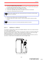
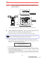
9.2.1 Battery Pack Replacement. . . . . . . . . . . . . . . . . . . . . . . . . . . . 9-5
9.2.2 Batteries in NX100 . . . . . . . . . . . . . . . . . . . . . . . . . . . . . . . . . . 9-6
9.2.3 Grease Replenishment/Exchange for Rotation-Axis
Speed Reducer. . . . . . . . . . . . . . . . . . . . . . . . . . . . . . . . . . . . . 9-7
Grease Replenishment (Refer to " Fig. 23 Grease
Inlet and Grease Exhaust Port for the Rotation-Axis
Speed Reducer ".) . . . . . . . . . . . . . . . . . . . . . . . . . . . . . . . . 9-7
Grease Exchange (Refer to " Fig. 23 Grease Inlet
and Grease Exhaust Port for the Rotation-Axis Speed
Reducer ".) . . . . . . . . . . . . . . . . . . . . . . . . . . . . . . . . . . . . . . 9-8
9.2.4 Grease Replenishment for S-, L-, U-, R-, B-, T-axis
Actuators. . . . . . . . . . . . . . . . . . . . . . . . . . . . . . . . . . . . . . . . . . 9-9
Grease Replenishment of Each Actuator (Refer to
" Fig. 24 Grease Inlets and Grease Exhaust Ports
for the S-, L-, U-, R-, B-, T-Axis Actuators ".) . . . . . . . . . . 9-10
9.2.5 Actuator Replacement . . . . . . . . . . . . . . . . . . . . . . . . . . . . . . 9-11
Actuator Replacement
(Example of the B-Axis Replacement Procedure) . . . . . . . 9-12
9.2.6 Interface Board. . . . . . . . . . . . . . . . . . . . . . . . . . . . . . . . . . . . 9-15
9.2.7 Brake Driver Board. . . . . . . . . . . . . . . . . . . . . . . . . . . . . . . . . 9-16
Alarm Causes and Corrective Actions . . . . . . . . . . . . . . . . 9-16
10 Recommended Spare Parts
8/59

1.1 Contents Confirmation
1-1
HW0483402
HW0483402
1Product Confirmation
1.1 Contents Confirmation
Confirm the contents of the delivery when the product arrives.
Standard delivery includes the following four items (Information for the content of optional
goods is given separately):
• Manipulator
• NX100
• Programming Pendant
• Manipulator Cables (Three cables, between manipulator and NX100)
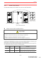
• Confirm that the manipulator and the NX100 have the same order num-
ber. Special care must be taken when more than one manipulator is to
be installed.
If the numbers do not match, manipulators may not perform as expected and cause injury
or damage.
CAUTION
9/59

1.2 Order Number Confirmation
1-2
HW0483402
HW0483402
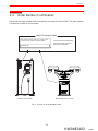
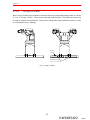
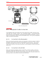
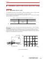
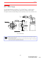
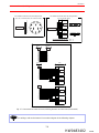
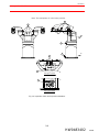
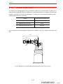
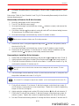
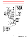
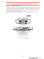
1.2 Order Number Confirmation
Check that the order number of the manipulator corresponds to the NX100. The order number
is located on a label as shown below.
Fig. 1 Location of Order Number Labels
THE MANIPULATOR AND THE CONTROLLER
SHOULD HAVE SAME ORDER NUMBER.
ORDER. No.
Label (Enlarged View)
Check that the manipulator
and the NX100 have the
same order number.
NX100
200V 50Hz kVA3PHASE220V 50/60Hz
NJ2484-1MADE IN JAPAN
DATE
SERIAL No.
ERCR-
TYPE
POWER SUPPLY ******
ORDER NO.
NJ1529
THE MANIPULATOR AND THE CONTROLLER
SHOULD HAVE SAME ORDER NUMBER.
WARNING
Do not open the door
RESET
OFF
TRIPPED
ON
N
P
O
E
T
R
G
Y
C
M
S
E
E
SELECT
SELECT
SELECT
PLAY TEACH
REMOTE
SERVO
POWER
S- X+
S+
MAIN
MENU
R-
xR+
x
ASSIST
COORD.
MULTI
DISPLAY
SWITCH
X-
yy
645
AUXILIARY
AUXILIARY
TIMER
1
WEAVING
COMPLETE
VOLTAGE
CURRENT
2
WELD
COMPLETE
3
RETRUCT
DELETE
BACK
INSERT
NEXT
L+L-
R-
LOCK
INTER
WEAVING
START
7
+
R+
B+B-
z
T-
WELD
START
8
FEED
9
TEST RUN
SHIFT
z
T+
EX-AXIS
SWITCH
ROBOT
SWITCH
-
SHIFT
Y+Y-
0
ENTER
CABCEK
INTER.
REF.
POINT
MODIFY
.-
VOLTAGE
CURRENT
SHORTCUT
MENU
NX100 (Front View) Manipulator (Back View)
10/59
Page is loading ...
Page is loading ...
Page is loading ...
Page is loading ...
Page is loading ...
Page is loading ...
Page is loading ...
Page is loading ...
Page is loading ...
Page is loading ...
Page is loading ...
Page is loading ...
Page is loading ...
Page is loading ...
Page is loading ...
Page is loading ...
Page is loading ...
Page is loading ...
Page is loading ...
Page is loading ...
Page is loading ...
Page is loading ...
Page is loading ...
Page is loading ...
Page is loading ...
Page is loading ...
Page is loading ...
Page is loading ...
Page is loading ...
Page is loading ...
Page is loading ...
Page is loading ...
Page is loading ...
Page is loading ...
Page is loading ...
Page is loading ...
Page is loading ...
Page is loading ...
Page is loading ...
Page is loading ...
Page is loading ...
Page is loading ...
Page is loading ...
Page is loading ...
Page is loading ...
Page is loading ...
Page is loading ...
Page is loading ...
Page is loading ...
-
 1
1
-
 2
2
-
 3
3
-
 4
4
-
 5
5
-
 6
6
-
 7
7
-
 8
8
-
 9
9
-
 10
10
-
 11
11
-
 12
12
-
 13
13
-
 14
14
-
 15
15
-
 16
16
-
 17
17
-
 18
18
-
 19
19
-
 20
20
-
 21
21
-
 22
22
-
 23
23
-
 24
24
-
 25
25
-
 26
26
-
 27
27
-
 28
28
-
 29
29
-
 30
30
-
 31
31
-
 32
32
-
 33
33
-
 34
34
-
 35
35
-
 36
36
-
 37
37
-
 38
38
-
 39
39
-
 40
40
-
 41
41
-
 42
42
-
 43
43
-
 44
44
-
 45
45
-
 46
46
-
 47
47
-
 48
48
-
 49
49
-
 50
50
-
 51
51
-
 52
52
-
 53
53
-
 54
54
-
 55
55
-
 56
56
-
 57
57
-
 58
58
-
 59
59
-
 60
60
-
 61
61
-
 62
62
-
 63
63
-
 64
64
-
 65
65
-
 66
66
-
 67
67
-
 68
68
-
 69
69


Motoman DA20 Manipulator Manual
- Type
- Manipulator Manual
- This manual is also suitable for
Ask a question and I''ll find the answer in the document
Finding information in a document is now easier with AI
Related papers


Other documents
-
YASKAWA motoman NX100 Instructions Manual
-
-
-
-
-
-
-
-
-