
HPAdvanceStack
Switch 208/224
Installationand
Reference Guide
HPJ3175A
HPJ3177A

YUMABOOK.BK : 0_frtcvr.fm5 Page 2 Thursday, February 20, 1997 9:35 AM

Perforate
✂
(over for more services)
HP Customer Support Services
How to get the latest software/agent firmware
You can download from the World Wide Web, HP FTP Library Service, CompuServe,
and HP BBS a compressed file (j3178xx.exe) containing the latest version of the HP
Switch 208/224 Management Module software and proprietary MIB. After you down-
load the file, extract the file by typing
filename
and pressing
[Enter].
For example, j317801 [Enter].
World Wide Web
http://www.hp.com/go/network_city
Select the “Support” section.
From this web site, you can also download information on the HP networking prod-
ucts. If you have a growing network, download the Designing HP AdvanceStack
Workgroup Networks Guide or call 1-800-752-0900 in the U.S. to receive a copy through
the mail.
HP FTP Library Service
1. FTP to Internet IP Address — ftp ftp.hp.com.
2. Log in as anonymous and press [Return] at the password prompt.
3. Enter bin to set the transfer type.
4. Enter cd /pub/networking/software.
5. Enter get
filename
to transfer the file to your computer, then quit.
CompuServe
1. Login to CompuServe.
2. Go to the “hp” service.
3. Select “HP Systems, Disks, Tapes, etc.”
4. Select “Networking Products” library.
5. Download
filename
and then quit.
HP BBS
Set your modem to no parity, eight bits, 1 stop bit, set speed up to 14400 bps, and with
your telecommunication program (e.g., Windows Terminal) dial (208) 344-1691 in the
U.S. to get the latest software for your HP networking product. For other countries,
see http://www.hp.com/cposupport/eschome.html.
Obtain the latest console code (j3178xx.exe) from:
HP FTP Library: ftp ftp-boi.external.hp.com
World Wide Web: http://www.hp.com/go/network_city
HP BBS: (208) 344-1691
(over)
YUMABOOK.BK : 0_perf.fm5 Page 1 Thursday, February 20, 1997 9:35 AM

Perforate
✂
HP FIRST Fax Retrieval Service
HP FIRST is an automated fax retrieval service that is available 24 hours a day, seven
days a week. HP FIRST provides information on the following topics:
■ Product information
■ Troubleshooting instructions
■ Technical reviews and articles
■ Configuration information
To access HP FIRST, dial one of the following phone numbers:
Additional HP Support Services
In addition to the above services, you can purchase various HP telephone support
services which provide you expert HP technical assistance:
■ Network Phone-In Support provides you support at an hourly rate. In the U.S.,
call 1-800-790-5544. In other countries, please contact your local HP Response
Center to see if this service is available in your country.
■ HP SupportPack Comprehensive Network Support provides complete prob-
lem resolution for medium to large interconnected local and wide area
networks. Contact your HP Authorized Reseller or the nearest HP Sales and
Support Office for more information.
HP offers other hardware support services. Please contact your reseller for more
information.
Location Phone Number
U.S. and Canada Only Dial 1 (800) 333-1917 with your fax machine or touch-tone phone
and press 1.
Outside the U.S. and Canada Dial 1 (208) 344-4809 from your fax machine and press 9.
To receive a list of currently available documents, enter document number 19941. The information
you requested will be sent to you by return fax. For other countries, see http://www.hp.com/
cposupport/eschome.html.
CompuServe: Go hpsys
Lib 7.
Download j3178xx.exe
Network Phone-In
Support (hourly):
1-800-790-5544
YUMABOOK.BK : 0_perf.fm5 Page 2 Thursday, February 20, 1997 9:35 AM

HP AdvanceStack Switch 208/224
Installation and Reference Guide
YUMABOOK.BK : 0_front.fm5 Page i Thursday, February 20, 1997 9:35 AM

Hewlett-Packard Company
8000 Foothills Boulevard, m/s 5552
Roseville, California 95747-5552
http://www.hp.com/go/network_city
© Copyright 1997 Hewlett-Packard Company
All Rights Reserved.
This document contains information which is protected by
copyright. Reproduction, adaptation, or translation without
prior permission is prohibited, except as allowed under the
copyright laws.
Publication Number
5966-5225
Edition 1
March 1997
Applicable Products
HP J3175A AdvanceStack Switch 208T
HP J3177A AdvanceStack Switch 224T
Disclaimer
The information contained in this document is subject to
change without notice.
HEWLETT-PACKARD COMPANY MAKES NO WARRANTY
OF ANY KIND WITH REGARD TO THIS MATERIAL,
INCLUDING, BUT NOT LIMITED TO, THE IMPLIED
WARRANTIES OF MERCHANTABILITY AND FITNESS
FOR A PARTICULAR PURPOSE. Hewlett-Packard shall not
be liable for errors contained herein or for incidental or
consequential damages in connection with the furnishing,
performance, or use of this material.
Hewlett-Packard assumes no responsibility for the use or
reliability of its software on equipment that is not furnished
by Hewlett-Packard.
Warranty
A copy of the specific warranty terms applicable to your
Hewlett-Packard products and replacement parts can be
obtained from your HP Sales and Service Office or
authorized dealer.
YUMABOOK.BK : 0_front.fm5 Page ii Thursday, February 20, 1997 9:35 AM

iii
Contents
1 Installing the Switch 208/224
Included Parts . . . . . . . . . . . . . . . . . . . . . . . . . . . . . . . . . . . . . . . . . . . . . . . . 1-2
Installation Steps . . . . . . . . . . . . . . . . . . . . . . . . . . . . . . . . . . . . . . . . . . . . . 1-2
1. Prepare the Installation Site . . . . . . . . . . . . . . . . . . . . . . . . . . . . . . . . 1-3
2. Install Any Optional Modules . . . . . . . . . . . . . . . . . . . . . . . . . . . . . . . 1-4
3. Verify the Switch’s Operation . . . . . . . . . . . . . . . . . . . . . . . . . . . . . . . 1-6
4. Mount the Switch . . . . . . . . . . . . . . . . . . . . . . . . . . . . . . . . . . . . . . . . . 1-8
5. Connect the Switch to a Power Source . . . . . . . . . . . . . . . . . . . . . . 1-12
6. Connect the Network Cables . . . . . . . . . . . . . . . . . . . . . . . . . . . . . . . 1-13
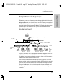
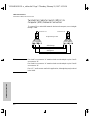
Sample Network Topologies . . . . . . . . . . . . . . . . . . . . . . . . . . . . . . . . . . 1-15
As a Segment Switch . . . . . . . . . . . . . . . . . . . . . . . . . . . . . . . . . . . . . . . . 1-15
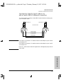
As a Desktop Switch . . . . . . . . . . . . . . . . . . . . . . . . . . . . . . . . . . . . . . . . 1-16
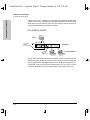
Connecting to a Backbone Switch . . . . . . . . . . . . . . . . . . . . . . . . . . . . 1-17
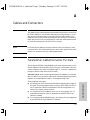
Cable Management . . . . . . . . . . . . . . . . . . . . . . . . . . . . . . . . . . . . . . . . . . . 1-18
Where to Go From Here . . . . . . . . . . . . . . . . . . . . . . . . . . . . . . . . . . . . . . 1-18
2 Switch 208/224 Description
Features . . . . . . . . . . . . . . . . . . . . . . . . . . . . . . . . . . . . . . . . . . . . . . . . . . . . . . 2-1
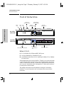
Front of the Switches . . . . . . . . . . . . . . . . . . . . . . . . . . . . . . . . . . . . . . . . . . 2-2
Network Ports . . . . . . . . . . . . . . . . . . . . . . . . . . . . . . . . . . . . . . . . . . . . . . 2-2
LEDs . . . . . . . . . . . . . . . . . . . . . . . . . . . . . . . . . . . . . . . . . . . . . . . . . . . . . . 2-3
Management Slot . . . . . . . . . . . . . . . . . . . . . . . . . . . . . . . . . . . . . . . . . . . . 2-4
Back of the Switches . . . . . . . . . . . . . . . . . . . . . . . . . . . . . . . . . . . . . . . . . . 2-5
Power Connectors . . . . . . . . . . . . . . . . . . . . . . . . . . . . . . . . . . . . . . . . . . . 2-5
Redundant Power Supply (RPS) Connector . . . . . . . . . . . . . . . . . . . . . 2-5
Expansion Slot . . . . . . . . . . . . . . . . . . . . . . . . . . . . . . . . . . . . . . . . . . . . . . 2-5
Switch Operation . . . . . . . . . . . . . . . . . . . . . . . . . . . . . . . . . . . . . . . . . . . . . . 2-6
Address Table Operation . . . . . . . . . . . . . . . . . . . . . . . . . . . . . . . . . . . . . 2-6
Simultaneous Network Communications . . . . . . . . . . . . . . . . . . . . . . . 2-7
YUMABOOK.BK : yumabook.TOC Page iii Thursday, February 20, 1997 9:35 AM

iv
3 Troubleshooting
Solutions to Common Problems . . . . . . . . . . . . . . . . . . . . . . . . . . . . . . . . 3-1
LED Error Indications . . . . . . . . . . . . . . . . . . . . . . . . . . . . . . . . . . . . . . . . . 3-3
Diagnostic Tests . . . . . . . . . . . . . . . . . . . . . . . . . . . . . . . . . . . . . . . . . . . . . . 3-4
Testing the Switch . . . . . . . . . . . . . . . . . . . . . . . . . . . . . . . . . . . . . . . . . . . 3-4
Testing Twisted-Pair Cabling . . . . . . . . . . . . . . . . . . . . . . . . . . . . . . . . . . 3-4
Testing End-to-End Network Communications . . . . . . . . . . . . . . . . . . 3-5
Testing Switch-to-Device Network Communications . . . . . . . . . . . . . 3-5
Resetting the Switch . . . . . . . . . . . . . . . . . . . . . . . . . . . . . . . . . . . . . . . . . 3-6
HP Customer Support Services . . . . . . . . . . . . . . . . . . . . . . . . . . . . . . . . . 3-6
A Cables and Connectors
Twisted-Pair Cable/Connector Pin-Outs . . . . . . . . . . . . . . . . . . . . . . . A-1
Twisted-Pair Cable for Switch (MDI-X) to
Computer (MDI) Network Connection . . . . . . . . . . . . . . . . . . . . . . . . A-2
Twisted-Pair Cable for Switch (MDI-X) to
Hub or Switch (MDI-X) Network Connection . . . . . . . . . . . . . . . . . . . A-3
Twisted-Pair Cable Pin Assignments . . . . . . . . . . . . . . . . . . . . . . . . . . A-4
Fiber-Optic Cables . . . . . . . . . . . . . . . . . . . . . . . . . . . . . . . . . . . . . . . . . . . A-4
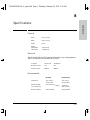
B Specifications
C Safety and Regulatory Statements
Mounting Precautions . . . . . . . . . . . . . . . . . . . . . . . . . . . . . . . . . . . . . . . . C-1
Power Precautions . . . . . . . . . . . . . . . . . . . . . . . . . . . . . . . . . . . . . . . . . . . C-2
Safety Information . . . . . . . . . . . . . . . . . . . . . . . . . . . . . . . . . . . . . . . . . . . C-3
Safety Information (Japanese) . . . . . . . . . . . . . . . . . . . . . . . . . . . . . . . C-8
Regulatory Statements . . . . . . . . . . . . . . . . . . . . . . . . . . . . . . . . . . . . . . . C-9
Declaration of Conformity . . . . . . . . . . . . . . . . . . . . . . . . . . . . . . . . . . . C-10
Index
YUMABOOK.BK : yumabook.TOC Page iv Thursday, February 20, 1997 9:35 AM

1-1
Installing the Switch 208/224
1
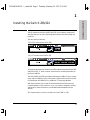
Installing the Switch 208/224
The HP AdvanceStack Switch 208T and 224T are low-latency, high-speed
switches that you can use to build high-performance switched workgroup
networks.
The two switch models are:
Throughout this manual, these switches will be abbreviated as the Switch 208T
and Switch 224T, or, when common characteristics are being described, as
the Switch 208/224.
The Switch 208T and 224T have eight and twenty-four 10Base-T ports, respec-
tively, and two 100Base-T ports: one fixed RJ-45 port and one transceiver slot
for installing an HP 100Base-TX or 100Base-FX Transceiver Module.
With these switches you can build a switched network infrastructure by
connecting hubs or other switches, or you can connect computers, printers,
and servers to these switches to provide dedicated bandwidth to those
devices.
This chapter shows you how to install your Switch 208T or 224T.
HP J3177A AdvanceStack Switch 224T
HP J3175A AdvanceStack Switch 208T
YUMABOOK.BK : 1_instal.fm5 Page 1 Thursday, February 20, 1997 9:35 AM

1-2
Installing the Switch 208/224
Included Parts
Installing the Switch 208/224
Included Parts
The Switch 208T and 224T have the following components shipped with them:
■ HP AdvanceStack Switch 208/224 Installation and Reference Guide
(5964-5225), this manual
■ Warranty booklet
■ Accessory kit (5063-8570)
• two mounting brackets
• two cable ties
• four 10 mm M3 thread-forming screws to attach the mounting
brackets to the switch
• four 5/8-inch number 12-24 screws to attach the switch to a rack
■ Power cord, one of the following:
Installation Steps
Follow these easy steps to install your switch. The rest of this chapter provides
details on these steps.
1. Prepare the installation site
2. Install any optional modules
3. Verify that the switch passes self test
4. Mount the switch
5. Connect power to the switch
6. Connect the network cables
Australia/New Zealand/China (8120-6810)
Denmark (8120-6814)
Europe (8120-6811)
Japan (8120-6798)
Switzerland (8120-6815)
United Kingdom (8120-6809)
United States/Canada (8120-6812)
YUMABOOK.BK : 1_instal.fm5 Page 2 Thursday, February 20, 1997 9:35 AM

1-3
Installing the Switch 208/224
Installation Steps
Installing the Switch 208/224
1. Prepare the Installation Site
■ Cabling Infrastructure - Ensure that the cabling infrastructure meets
the necessary network specifications:
• For the 10Base-T ports, use category 3, 4, or 5, four-pair, 100 ohm UTP
(unshielded twisted-pair) cables. Cable lengths can be up to 100
meters for category 3 or 4, and 150 meters for category 5. For
connecting these ports to end nodes, use “straight-through” cable; for
connecting to hubs or other switches, use “crossover” cable. See
appendix A, “Cables and Connectors” for more information
• For the fixed 100Base-TX port and 100Base-TX transceivers that you
install in the transceiver slot, use category 5, 100-ohm UTP cables.
Cable lengths can be up to 100 meters.
For connecting these ports to end nodes, use “straight-through” cable;
for connecting to hubs and switches, use “crossover” cable.
• For 100Base-FX transceivers that you install in the transceiver slot,
use 1300 nm multi-mode fiber-optic cables that are fitted with SC
connectors, and conform to ISO/IEC 793-2 type B1 and ITU-T G.652
standards. Cable lengths can be up to 1 kilometer.
■ Installation Precautions -
• Before installing the switch, plan its location and orientation relative
to other devices and equipment. In the front of the switch, leave at
least 3 inches (7.6 cm) of space for the twisted-pair and fiber-optic
cabling. In the back, leave at least 1 1/2 inches (3.8 cm) of space for
the power cord.
• Caution: Ensure that the switch does not overload the power
circuits, wiring, and over-current protection. To determine the possi-
bility of overloading the supply circuits, add together the ampere
ratings of all devices installed on the same circuit as the switch and
compare the total with the rating limit for the circuit. The maximum
ampere ratings are usually printed on the devices near the AC power
connectors.
• Caution: Ensure that the power source circuits are properly
grounded. See the Safety Statements at the end of this manual.
• Do not install the switch in an environment where the operating
ambient temperature might exceed 55°C (131°F).
• Make sure the air flow around the sides of the switch is not restricted.
YUMABOOK.BK : 1_instal.fm5 Page 3 Thursday, February 20, 1997 9:35 AM

1-4
Installing the Switch 208/224
Installation Steps
Installing the Switch 208/224
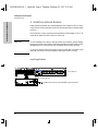
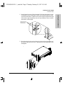
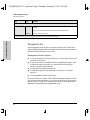
2. Install Any Optional Modules
Install optional modules into the Management Slot, Expansion Slot, or trans-
ceiver slot by following the instructions in the manuals that accompany these
products.
Each of the slot covers can be removed with either a flat-bladed or Torx T-10
screwdriver. Retain the slot covers for future use.
Caution To avoid damage to circuitry in the switch and any modules, always unplug
the power from the switch before installing a module into the Expansion Slot,
Management Slot, or transceiver slot, and when removing any modules.
If you do not install an optional module, make sure that the cover plate is still
attached over the slot for safe operation and proper switch cooling.
Installing Modules
HP J3178A AdvanceStack Switch 208/224 Management Module
Front of Switch
Management Slot
YUMABOOK.BK : 1_instal.fm5 Page 4 Thursday, February 20, 1997 9:35 AM

1-5
Installing the Switch 208/224
Installation Steps
Installing the Switch 208/224
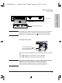
Note An expansion slot module uses the switch port 1 circuitry to communicate
with the other switch ports. Therefore, installing an expansion module
disables port 1 as reflected by the LED on the front of the switch.
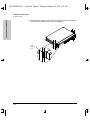
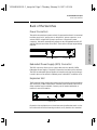
Installing Transceivers
Install either of these HP 100Base-T transceiver modules into the transceiver
slot:
- HP J3192B 100Base-TX Twisted-Pair Transceiver Module
- HP J3193B 100Base-FX Fiber-Optic Transceiver Module
Cautions Make sure you install only the “B” model or later versions of these
100Base-T transceiver modules into the Switch 208/224.
Do not install any 100VG transceiver modules in this slot.
Back of Switch
Expansion Slot
supported expansion module
Blue color bar with “100T” in it,
and “B”, or later, model number
identifies a correct transceiver
for the Switch 208T and 224T
YUMABOOK.BK : 1_instal.fm5 Page 5 Thursday, February 20, 1997 9:35 AM

1-6
Installing the Switch 208/224
Installation Steps
Installing the Switch 208/224
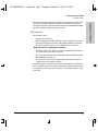
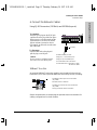
3. Verify the Switch’s Operation
After you have installed any modules, but before mounting the switch in its
network location, you should first verify that it is working properly by plugging
it into a power source and verifying that it passes its self test.
1. Connect the power cord supplied with the switch to the power connector
on the back of the switch, and then into a properly grounded electrical
outlet.
Note The Switch 208/224 does not have a power switch. It is powered on when the
power cord is connected to the switch and to a power source.
If your installation requires a different power cord than the one supplied with
the switch, be sure to use a power cord displaying the mark of the safety
agency that defines the regulations for power cords in your country. The mark
is your assurance that the power cord can be used safely with the switch.
2. Check the LEDs on the switch’s front panel (and on the Switch Manage-
ment Module, if one is installed in the switch). The LED behavior is
described on the next page.
Connect power cord to
p
ower connector.
switch LEDs
Switch Management Module LEDs
YUMABOOK.BK : 1_instal.fm5 Page 6 Thursday, February 20, 1997 9:35 AM

1-7
Installing the Switch 208/224
Installation Steps
Installing the Switch 208/224
When the switch is powered on, it performs its diagnostic self test. With
the Switch Management Module installed, the self test takes approxi-
mately 15 seconds to complete. Without the Switch Management Module,
the test completes in approximately 4 seconds.
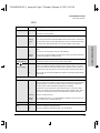
LED Behavior:
During the self test:
• Initially, all LEDs are on.
• With a Management Module installed, the switch port LEDs all go off
after approximately 10 seconds, and the Management Module Self
Test and Fault LEDs stay on for an additional 5 to 7 seconds.
When the self test completes successfully:
• The Power LED and, if an RPS is connected, the RPS LED remain on.
The “100” LED for port A also stays on.
• The Fault LED on the switch, and the Self Test and Fault LEDs on the
Management Module go off.
• The port LEDs go into their normal operational mode, if they are
connected to active network devices.
If the LED display is different than what is described above, especially if
any Fault LEDs stay on for more than 30 seconds or flash, the self test has
not completed correctly. Refer to chapter 3, “Troubleshooting” for diag-
nostic help.
YUMABOOK.BK : 1_instal.fm5 Page 7 Thursday, February 20, 1997 9:35 AM

1-8
Installing the Switch 208/224
Installation Steps
Installing the Switch 208/224
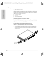
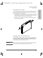
4. Mount the Switch
After the modules are inserted and you have verified that the switch passes
self test, you are ready to mount the switch in a stable location. The Switch
208/224 can be mounted in three ways:
■ in a rack or cabinet
■ on a wall
■ on a horizontal surface
Mounting the Switch in a Rack or Cabinet
The Switch 208/224 is designed to be mounted in any EIA-standard 19-inch
telco equipment rack. To order a rack for your switch, call HP at 1-800-538-
8787 to order product number HP 46298D.
For safe operation, please read the mounting precautions in
appendix C, “Safety and Regulatory” before mounting a switch.
1. Use a #1 Phillips (cross-head) or Pozidriv screwdriver and attach the
mounting brackets to the switch with the included 10-mm M3 thread-
forming screws.
10 mm
M3
screws
YUMABOOK.BK : 1_instal.fm5 Page 8 Thursday, February 20, 1997 9:35 AM

1-9
Installing the Switch 208/224
Installation Steps
Installing the Switch 208/224
2. Partially install a screw (5/8-inch number 12-24) into the top hole of a pair
of holes that are 0.5 inches apart in each rack/cabinet upright as shown
in the illustration below. Tighten each screw enough to support the weight
of the switch, approximately two turns. Ensure that the screws are at the
same level in each upright.
3. Place the switch in the rack and lower it so the notches in the bottom of
the bracket slide onto the screws. Tighten these screws-be careful not to
overtighten.
Insert a screw into
the top hole of a
close (0.5-inch)
YUMABOOK.BK : 1_instal.fm5 Page 9 Thursday, February 20, 1997 9:35 AM

1-10
Installing the Switch 208/224
Installation Steps
Installing the Switch 208/224
4. Install the other number 12-24 screw into the upper hole in each bracket.
Tighten these screws-be careful not to overtighten.
install
additional
screw
YUMABOOK.BK : 1_instal.fm5 Page 10 Thursday, February 20, 1997 9:35 AM

1-11
Installing the Switch 208/224
Installation Steps
Installing the Switch 208/224
Mounting the Switch on a Wall
You can mount the switch on a wall as shown in the illustration below. Note
that the switch should be mounted only to a wall or wood surface that is at
least 1/2-inch plywood or its equivalent.
1. Using a Phillips (cross-head) or Pozidriv screwdriver with the 10-mm M3
thread-forming screws included in the accessory kit, attach the mounting
brackets to the switch as shown in the illustration below.
2. Attach the switch to the wall or wood surface with 5/8-inch number 12
wood screws (not included}.
Mounting the Switch on a Horizontal Surface
Place the switch on a table or other horizontal surface. Use a sturdy surface
in an uncluttered area. You may want to secure the networking cables and
switch power cord to the table leg or other part of the surface structure to
help prevent people from tripping over the cords.
Caution Make sure the air flow is not restricted around the sides and back of the switch,
and around the HP J2692A Redundant Power Supply, if used.
YUMABOOK.BK : 1_instal.fm5 Page 11 Thursday, February 20, 1997 9:35 AM

1-12
Installing the Switch 208/224
Installation Steps
Installing the Switch 208/224
5. Connect the Switch to a Power Source
1. (Optional.) This product supports use of the HP J2962A Redundant
Power Supply (RPS), which can help ensure continuous switch operation
in the event of a power failure. If you have this HP RPS, connect the RPS
to the switch now and connect the RPS to an appropriate AC power
source.
Caution When installed, the RPS is used in place of the standard power cord, so make
sure you disconnect the standard power cord from the switch before you
connect the RPS. Using both the standard power cord and the RPS at the same
time could damage the switch’s components.
For information on how to install and connect the HP RPS, refer to the
documentation supplied with the RPS.
2. If you are not using an RPS, plug the included power cord into the switch's
power cord receptacle and into an AC power source as shown below.
3. Re-check the LEDs during self test. Initially, all LEDs are on. After the
four-second self test (or 15 second self test with Management Module),
only the Power and port A “100” LEDs (and optionally the RPS LED) are
on. See “LED Behavior” on page 7.
Back of RPS
Back of Switch
power receptacle
on the back of the switch
YUMABOOK.BK : 1_instal.fm5 Page 12 Thursday, February 20, 1997 9:35 AM
Page is loading ...
Page is loading ...
Page is loading ...
Page is loading ...
Page is loading ...
Page is loading ...
Page is loading ...
Page is loading ...
Page is loading ...
Page is loading ...
Page is loading ...
Page is loading ...
Page is loading ...
Page is loading ...
Page is loading ...
Page is loading ...
Page is loading ...
Page is loading ...
Page is loading ...
Page is loading ...
Page is loading ...
Page is loading ...
Page is loading ...
Page is loading ...
Page is loading ...
Page is loading ...
Page is loading ...
Page is loading ...
Page is loading ...
Page is loading ...
Page is loading ...
Page is loading ...
Page is loading ...
Page is loading ...
Page is loading ...
Page is loading ...
Page is loading ...
Page is loading ...
Page is loading ...
Page is loading ...
Page is loading ...
Page is loading ...
-
 1
1
-
 2
2
-
 3
3
-
 4
4
-
 5
5
-
 6
6
-
 7
7
-
 8
8
-
 9
9
-
 10
10
-
 11
11
-
 12
12
-
 13
13
-
 14
14
-
 15
15
-
 16
16
-
 17
17
-
 18
18
-
 19
19
-
 20
20
-
 21
21
-
 22
22
-
 23
23
-
 24
24
-
 25
25
-
 26
26
-
 27
27
-
 28
28
-
 29
29
-
 30
30
-
 31
31
-
 32
32
-
 33
33
-
 34
34
-
 35
35
-
 36
36
-
 37
37
-
 38
38
-
 39
39
-
 40
40
-
 41
41
-
 42
42
-
 43
43
-
 44
44
-
 45
45
-
 46
46
-
 47
47
-
 48
48
-
 49
49
-
 50
50
-
 51
51
-
 52
52
-
 53
53
-
 54
54
-
 55
55
-
 56
56
-
 57
57
-
 58
58
-
 59
59
-
 60
60
-
 61
61
-
 62
62


HP J3177A User manual
- Category
- Network switches
- Type
- User manual
Ask a question and I''ll find the answer in the document
Finding information in a document is now easier with AI
Related papers
Other documents
-
Sitecom LN-131 Datasheet
-
Panasonic VLGT001A Operating instructions
-
Cisco Systems BPX 8600 Series Installation & Configuration Guide
-
Transition Networks FAST ETHERNET E-TX-MC01 User manual
-
 Hood J3250M User manual
-
3com SuperStack 3 Switch 4400 FX Getting Started Manual
-
3com 1100 User manual
-
-
HP (Hewlett-Packard) Laptop 2500 User manual
-
SMC Switch SMC8848M User manual
