
FrameSaver
®
SLV
Configuration Reference
Document No. 9000-A2-GB31-00
December 2002

A December 2002 9000-A2-GB31-00
Copyright © 2002 Paradyne Corporation.
All rights reserved.
Printed in U.S.A.
Notice
This publication is protected by federal copyright law. No part of this publication may be copied or distributed,
transmitted, transcribed, stored in a retrieval system, or translated into any human or computer language in any form or
by any means, electronic, mechanical, magnetic, manual or otherwise, or disclosed to third parties without the express
written permission of Paradyne Corporation, 8545 126th Ave. N., Largo, FL 33773.
Paradyne Corporation makes no representation or warranties with respect to the contents hereof and specifically
disclaims any implied warranties of merchantability or fitness for a particular purpose. Further, Paradyne Corporation
reserves the right to revise this publication and to make changes from time to time in the contents hereof without
obligation of Paradyne Corporation to notify any person of such revision or changes.
Changes and enhancements to the product and to the information herein will be documented and issued as a new
release to this manual.
Warranty, Sales, Service, and Training Information
Contact your local sales representative, service representative, or distributor directly for any help needed. For additional
information concerning warranty, sales, service, repair, installation, documentation, training, distributor locations, or
Paradyne worldwide office locations, use one of the following methods:
Internet: Visit the Paradyne World Wide Web site at www.paradyne.com. (Be sure to register your warranty at
www.paradyne.com/warranty.)
Telephone: Call our automated system to receive current information by fax or to speak with a company
representative.
— Within the U.S.A., call 1-800-870-2221
— Outside the U.S.A., call 1-727-530-2340
Document Feedback
We welcome your comments and suggestions about this document. Please mail them to Technical Publications,
Paradyne Corporation, 8545 126th Ave. N., Largo, FL 33773, or send e-mail to userdoc@paradyne.com. Include the
number and title of this document in your correspondence. Please include your name and phone number if you are
willing to provide additional clarification.
Trademarks
ACCULINK, COMSPHERE, FrameSaver, Hotwire, MVL, NextEDGE, OpenLane, and Performance Wizard are
registered trademarks of Paradyne Corporation. GranDSLAM, GrandVIEW, ReachDSL, and TruePut are trademarks of
Paradyne Corporation. All other products and services mentioned herein are the trademarks, service marks, registered
trademarks, or registered service marks of their respective owners.
Patent Notification
FrameSaver products are protected by U.S. Patents: 5,550,700 and 5,654,966. Other patents are pending.

9000-A2-GB31-00 December 2002 i
Contents
About This Guide
n Purpose and Intended Audience . . . . . . . . . . . . . . . . . . . . . . . . . . . . . v
n Document Organization . . . . . . . . . . . . . . . . . . . . . . . . . . . . . . . . . . . . v
n Product-Related Documents . . . . . . . . . . . . . . . . . . . . . . . . . . . . . . . . vi
n Conventions Used . . . . . . . . . . . . . . . . . . . . . . . . . . . . . . . . . . . . . . . . viii
1 Configuration Procedures
n Configuration Menu . . . . . . . . . . . . . . . . . . . . . . . . . . . . . . . . . . . . . . . 1-2
n Configuration Option Areas . . . . . . . . . . . . . . . . . . . . . . . . . . . . . . . . . 1-3
n Accessing and Displaying Configuration Options . . . . . . . . . . . . . . . . 1-4
n Changing Configuration Options . . . . . . . . . . . . . . . . . . . . . . . . . . . . . 1-5
n Saving Configuration Options . . . . . . . . . . . . . . . . . . . . . . . . . . . . . . . 1-6
2 Basic Configuration
n Using the Easy Install Feature . . . . . . . . . . . . . . . . . . . . . . . . . . . . . . . 2-2
n Using RIP with FrameSaver SLV CSU/DSUs . . . . . . . . . . . . . . . . . . . 2-11
n Entering System Information and Setting the System Clock . . . . . . . . 2-12
n Setting Up Auto-Configuration . . . . . . . . . . . . . . . . . . . . . . . . . . . . . . . 2-13
Selecting a Frame Relay Discovery Mode. . . . . . . . . . . . . . . . . . . 2-14
Automatically Removing a Circuit . . . . . . . . . . . . . . . . . . . . . . . . . 2-16
3 Configuration Options
n Configuration Option Tables . . . . . . . . . . . . . . . . . . . . . . . . . . . . . . . . 3-1
n Configuring the Overall System . . . . . . . . . . . . . . . . . . . . . . . . . . . . . . 3-3
Configuring Frame Relay and LMI for the System (CSU/DSUs) . . 3-3
Configuring PPP Options. . . . . . . . . . . . . . . . . . . . . . . . . . . . . . . . 3-7
Configuring Class of Service Definitions . . . . . . . . . . . . . . . . . . . . 3-8
Code Point Definitions . . . . . . . . . . . . . . . . . . . . . . . . . . . . . . . . . . 3-10
Configuring Service Level Verification Options . . . . . . . . . . . . . . . 3-11
Configuring General System Options . . . . . . . . . . . . . . . . . . . . . . 3-14

Contents
ii December 2002 9000-A2-GB31-00
n Configuring Physical Interfaces . . . . . . . . . . . . . . . . . . . . . . . . . . . . . . 3-17
Configuring the Network Interface . . . . . . . . . . . . . . . . . . . . . . . . . 3-17
T1 Network Interface . . . . . . . . . . . . . . . . . . . . . . . . . . . . . . . . . . . 3-18
T3 Network Interface . . . . . . . . . . . . . . . . . . . . . . . . . . . . . . . . . . . 3-22
DDS Network Interface . . . . . . . . . . . . . . . . . . . . . . . . . . . . . . . . . 3-23
IDSL Network Interface . . . . . . . . . . . . . . . . . . . . . . . . . . . . . . . . . 3-25
SDSL Network Interface . . . . . . . . . . . . . . . . . . . . . . . . . . . . . . . . 3-26
SHDSL Network Interface . . . . . . . . . . . . . . . . . . . . . . . . . . . . . . . 3-27
Synchronous Network Interface. . . . . . . . . . . . . . . . . . . . . . . . . . . 3-28
HSSI Network Interface . . . . . . . . . . . . . . . . . . . . . . . . . . . . . . . . . 3-30
Configuring a User Data Port (CSU/DSUs) . . . . . . . . . . . . . . . . . . 3-31
V.35 Data Port Physical Interface . . . . . . . . . . . . . . . . . . . . . . . . . 3-31
EIA-530-A/X.21/V.35 Data Port Physical Interface . . . . . . . . . . . . 3-36
HSSI Data Port Physical Interface. . . . . . . . . . . . . . . . . . . . . . . . . 3-38
Configuring the T3 User Port (9520-ILM) . . . . . . . . . . . . . . . . . . . 3-41
Configuring the DSX-1 Interface (9126, 9128) . . . . . . . . . . . . . . . 3-42
Configuring the ISDN DBM Interface (9126, 9128, 9626) . . . . . . . 3-44
Setting Up ISDN Link Profiles (9126, 9128, 9626) . . . . . . . . . . . . 3-48
n Assigning Time Slots/Cross Connections . . . . . . . . . . . . . . . . . . . . . . 3-50
Assigning Time Slots to the Network Interface . . . . . . . . . . . . . . . 3-51
Assigning DSX-1 Time Slots to the Network Interface . . . . . . . . . 3-52
Assigning a Synchronous Data Port to Network or DSX-1 Time Slots 3-
58
Clearing Assignments . . . . . . . . . . . . . . . . . . . . . . . . . . . . . . . . . . 3-59
n Configuring Frame Relay for an Interface . . . . . . . . . . . . . . . . . . . . . . 3-60
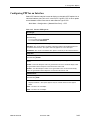
n Configuring PPP for an Interface . . . . . . . . . . . . . . . . . . . . . . . . . . . . . 3-63
n Manually Configuring DLCI Records . . . . . . . . . . . . . . . . . . . . . . . . . . 3-64
n Configuring Circuit Records for the Network Interface. . . . . . . . . . . . . 3-68
n Configuring ATM for the Network Interface . . . . . . . . . . . . . . . . . . . . . 3-71
n Configuring PVC Connections . . . . . . . . . . . . . . . . . . . . . . . . . . . . . . . 3-72
n Configuring the IP Path List . . . . . . . . . . . . . . . . . . . . . . . . . . . . . . . . . 3-76
n Setting Up Management and Communication Options . . . . . . . . . . . . 3-77
Configuring Node IP Information . . . . . . . . . . . . . . . . . . . . . . . . . . 3-78
Configuring Management PVCs . . . . . . . . . . . . . . . . . . . . . . . . . . 3-82
Configuring General SNMP Management . . . . . . . . . . . . . . . . . . . 3-88
Configuring Telnet and/or FTP Session Support . . . . . . . . . . . . . . 3-89
Configuring SNMP NMS Security . . . . . . . . . . . . . . . . . . . . . . . . . 3-92
Configuring SNMP Traps and Trap Dial-Out . . . . . . . . . . . . . . . . . 3-93
Configuring Ethernet Management . . . . . . . . . . . . . . . . . . . . . . . . 3-99
Configuring the Communication Port. . . . . . . . . . . . . . . . . . . . . . . 3-101
Configuring the Modem Port . . . . . . . . . . . . . . . . . . . . . . . . . . . . . 3-105
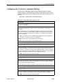
n Configuring the Criteria for Automatic Backup . . . . . . . . . . . . . . . . . . . 3-109

Contents
9000-A2-GB31-00 December 2002
iii
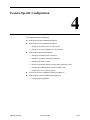
4 Feature-Specific Configuration
n Setting Up an External Modem . . . . . . . . . . . . . . . . . . . . . . . . . . . . . . 4-2
n Setting Up an Internal Modem . . . . . . . . . . . . . . . . . . . . . . . . . . . . . . . 4-3
Setting Up Call Directories for Trap Dial-Out. . . . . . . . . . . . . . . . . 4-3
Setting Up to Use the Modem PassThru Feature . . . . . . . . . . . . . 4-4
n Setting Up Dial Backup . . . . . . . . . . . . . . . . . . . . . . . . . . . . . . . . . . . . 4-5
Setting Up the DBM Physical Interface . . . . . . . . . . . . . . . . . . . . . 4-5
Setting Up Automatic Backup Configuration . . . . . . . . . . . . . . . . . 4-6
Modifying ISDN Link Profiles . . . . . . . . . . . . . . . . . . . . . . . . . . . . . 4-9
Restricting Automatic Backup and Configuring Backup Timers . . 4-10
Configuring the DBM Interface to Send SNMP Traps . . . . . . . . . . 4-11
Assigning DLCIs to a Backup Group . . . . . . . . . . . . . . . . . . . . . . . 4-11
n PVC Backup Over the Network Interface. . . . . . . . . . . . . . . . . . . . . . . 4-12
n Setting Up Back-to-Back Operation . . . . . . . . . . . . . . . . . . . . . . . . . . . 4-12
Changing Operating Mode. . . . . . . . . . . . . . . . . . . . . . . . . . . . . . . 4-12
Index

Contents
iv December 2002 9000-A2-GB31-00

9000-A2-GB31-00 December 2002 v
About This Guide
Purpose and Intended Audience
This document lists and describes the configuration options of the following
FrameSaver SLV CSU/DSUs and routers running firmware release 2.1 or above:
9123, 9126, 9128 standalone, 9128 carrier-mount, 9520, 9520-ILM, 9623, 9626,
9720, 9783, 9788, 9820-2M, 9820-8M, and 9820-45M.
Features introduced in firmware release 2.1 are described in this manual but may
not be available in all models.
Document Organization
A master glossary of terms and acronyms used in Paradyne documents is
available on the World Wide Web at www.paradyne.com. Select Support
→
Technical Manuals → Technical Glossary.
Section Description
Chapter 1, Configuration
Procedures
Shows how to access and save configuration
options.
Chapter 2, Basic Configuration Describes the Easy Install screens, how to set up
RIP, and using Auto-Configuration.
Chapter 3, Configuration Options Describes configuration options for CSU/DSUs and
routers.
Chapter 4, Feature-Specific
Configuration
Provides procedures for setting up internal and
external modems, Data Backup Modules (DBMs),
and back-to-back operation.
Index Lists key terms, acronyms, concepts, and sections.

About This Guide
vi December 2002 9000-A2-GB31-00
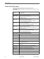
Product-Related Documents
Complete Paradyne documentation for this product is available at
www.paradyne.com. Select Support
→Technical Manuals →FrameSaver Frame
Relay Devices.
Document
Number Document Title
The FrameSaver SLV reference library contains:
9000-A2-GB30 FrameSaver SLV Technical Description
Describes the features, interfaces, and cables for FrameSaver SLV
CSU/DSUs and routers.
9000-A2-GB31 FrameSaver SLV Configuration Reference
Lists and describes the configuration options available for
FrameSaver SLV CSU/DSUs and routers.
9000-A2-GB32 FrameSaver SLV SNMP Reference
Describes MIB details, SNMP traps, and RMON data collection
used for FrameSaver SLV CSU/DSUs and routers.
9000-A2-GB33 FrameSaver SLV Operations Guide
Explains how to operate and troubleshoot FrameSaver SLV
CSU/DSUs and routers.
9000-A2-GB34 FrameSaver SLV Router Command Line Interface
Describes special configuration procedures and the command line
interface for FrameSaver SLV routers.
Other FrameSaver model-specific documentation includes:
9000-A2-GN19 FrameSaver SLV ISDN Installation Instructions
9000-A2-GN1D 9000 Series Access Carrier Installation Instructions
9123-A2-GN10 FrameSaver FLEX 9123 Installation Instructions
9126-A2-GN11 FrameSaver SLV 9126 1-Slot Unit Installation Instructions
9126-A2-GN12 FrameSaver SLV 9126 Router Installation Instructions
9128-A2-GN10 FrameSaver SLV 9128 1-Slot Housing-to-9000 Series Access
Carrier Upgrade Instructions
9128-A2-GN11 FrameSaver SLV 9128 Network Access Module (NAM) Installation
Instructions
9128-A2-GN12 FrameSaver SLV 9128 1-Slot Unit Installation Instruction
9520-A2-GN10 FrameSaver SLV 9520 Installation Instructions
9520-A2-GN11 FrameSaver SLV 9520-ILM Installation Instructions
9623-A2-GN10 FrameSaver FLEX 9623 Installation Instruction
9626-A2-GN10 FrameSaver SLV 9626 Installation Instructions
9783-A2-GN10 Framesaver DSL 9783 CSU/DSU Installation Instructions

About This Guide
9000-A2-GB31-00 December 2002
vii
To order a paper copy of this or any of the above documents:
n Within the U.S.A., call 1-800-PARADYNE (1-800-727-2396)
n Outside the U.S.A., call 1-727-530-8623
9783-A2-GN11 FrameSaver DSL 9783 Router Installation Instructions
9788-A2-GN10 Framesaver DSL 9788 CSU/DSU Installation Instructions
9788-A2-GN11 Framesaver DSL 9788 Router Installation Instructions
9820-A2-GN10 FrameSaver SLV, Models 9820-2M and 9820-8M, Installation
Instructions
9820-A2-GN11 FrameSaver SLV, Model 9820-45M, Installation Instructions
Document
Number Document Title

About This Guide
viii December 2002 9000-A2-GB31-00
Conventions Used
Convention Used When Used
Italic To indicate variable information (for example, DLCI nnnn,
where nnnn denotes a 4-digit number).
Menu sequence: To provide an abbreviated method for indicating the
selections to be made from a menu or selections from within
a menu before performing a procedural step.
For example,
Main Menu →Status → System and Test Status indicates
that you should select Status from the Main Menu, then
select System and Test Status.
(Path:) To provide a check point that coincides with the menu path
shown at the top of the screen. Always shown within
parentheses so you can verify that you are referencing the
correct table (e.g., Path: main/config/alarm).
Brackets [ ] To indicate multiple selection choices when more than one
selection is available (e.g., Performance
Statistics→ Status→ [Network/Port-1]).
Text highlighted in blue To indicate a hyperlink to additional information when viewing
this manual online. Click on the highlighted text.


1. Configuration Procedures
1-2 December 2002 9000-A2-GB31-00
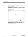
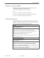
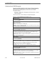
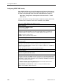
Configuration Menu
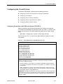
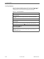
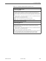
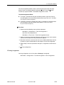
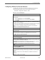
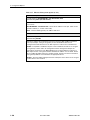
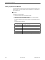
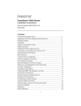
Configuration option settings determine how the FrameSaver unit operates. Use
the FrameSaver unit’s Configuration Edit/Display menu to display or change
configuration option settings.
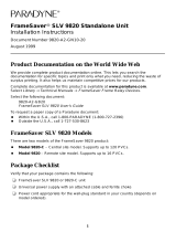
Configuration options available depend on the model and its features. The
Configuration Edit/Display menu shown below is for a FrameSaver SLV 9128 with
the optional ISDN backup feature.
Configuration Menu Example
Changing an Auto-Configuration setting can also change the FrameSaver unit’s
configuration. See Setting Up Auto-Configuration in Chapter 2, Basic
Configuration, for additional information.
main/config 9128-II
Device Name: Node A 11/01/2002 09:32
CONFIGURATION EDIT/DISPLAY
System
Network
DSX-1
Data Ports
ISDN
Time Slot Assignment
PVC Connections
Management and Communication
Auto Backup Criteria
--------------------------------------------------------------------------------
Ctrl-a to access these functions, ESC for previous menu M
ainMenu Exit
S
ave

1. Configuration Procedures
9000-A2-GB31-00 December 2002
1-3
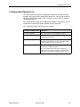
Configuration Option Areas
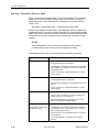
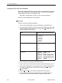
The FrameSaver unit arrives with configured factory default settings, which are
located in the Factory Default Configuration option area. You can find the default
settings for configuration options in the Configuration Option Tables in Chapter 3,
Configuration Options.
If the factory default settings do not support your network’s configuration, you can
customize the configuration options to better suit your application.
Four configuration option storage areas are available.
Configuration Option Area Description
Current Configuration The currently active set of configuration options.
Customer Configuration An alternate set of configuration options that you can set
up and store for future use.
Scratchpad Configuration An alternate configuration area for temporary use. The
Scratchpad configuration is reset to the factory default
settings when the unit is powered off and on.
Default Factory Configuration A read-only configuration area containing the factory
default set of configuration options.
You can load and edit default factory configuration
settings, but you can save changes only to the Current,
Customer, or Scratchpad configuration option areas.

1. Configuration Procedures
1-4 December 2002 9000-A2-GB31-00
Accessing and Displaying Configuration Options
To access and display configuration options, load (copy) the applicable
configuration option set into the edit area.
Procedure
To load a set of configuration options for editing:
1. From the Main Menu, press the down arrow key so the cursor is on
Configuration.
2. Press Enter to display the Configuration menu. The Load Configuration
From: menu appears.
NOTE:
Loading a configuration with many DLCIs from a unit’s Customer or
Scratchpad configuration option area may take time. Allow a minute or
more for the file to be loaded.
3. Select the configuration option area from which you want to load configuration
options and press Enter (Current Configuration, Customer Configuration,
Scratchpad Configuration, or Default Factory Configuration).
The selected set of configuration options is loaded into the configuration edit
area and the Configuration Edit/Display menu appears.
This sequence of steps would be shown as the menu selection sequence:
Main Menu
→ Configuration

1. Configuration Procedures
9000-A2-GB31-00 December 2002
1-5
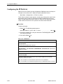
Changing Configuration Options
Procedure
To change configuration option settings:
1. From the Configuration Edit/Display menu, select a set of configuration
options and press Enter.
For example:
Configuration
→ PVC Connections
2. Select the configuration options that are applicable to your network, and make
appropriate changes to the setting(s). See the FrameSaver SLV Operations
Guide for additional information.
When creating new PVC connections or management PVCs, some
configuration options will be blank. For a valid setting to appear, Tab to the
configuration option and press the spacebar.
3. Repeat Steps 1 and 2 until all changes are complete.
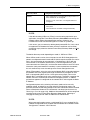
NOTES:
— Only Security Access Level 1 users can change configuration options.
— Security Access Level 2 users can only view configuration options and run
tests.
— Security Access Level 3 users can only view configuration options; they
cannot change configuration options or run tests.

1. Configuration Procedures
1-6 December 2002 9000-A2-GB31-00
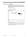
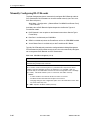
Saving Configuration Options
When changes to the configuration options are complete, use the Save function
key to save your changes to either the Current, Customer, or Scratchpad
configuration areas. Note that the Scratchpad configuration is reset to the factory
default settings when the unit is powered off and on.
Procedure
To save the configuration option changes:
1. Press Ctrl-a to switch to the function key area at the bottom of the screen.
2. Type s or S to select the S
ave function and press Enter.
The Save Configuration To: screen appears.
NOTE:
If you try to exit the Configuration menu without saving changes, a Save
Configuration screen appears requiring a Yes or No response.
— If you select N
o, the Main Menu screen reappears and the changes
are not saved.
— If you select Y
es, the Save Configuration To: screen appears.
3. Select the configuration option area to which you want to save your changes
(normally the Current Configuration) and press Enter.
When Save is complete, Command Complete appears in the message area
at the bottom of the screen.
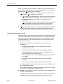
NOTE:
There are other methods of changing configurations, like SNMP and
Auto-Configuration. Since multiple sessions can be active at the same
time, the last change made overwrites any previous or current changes
being made. For instance:
— Saving your configuration changes would cause configuration
changes made via another method to be lost.
— If you are making changes and someone else makes changes and
saves them, your changes would be lost.

9000-A2-GB31-00 December 2002 2-1
2
Basic Configuration
This chapter includes the following:
n Using the Easy Install Feature on page 2-2
n Using RIP with FrameSaver SLV CSU/DSUs on page 2-11
n Entering System Information and Setting the System Clock on page 2-12
n Setting Up Auto-Configuration on page 2-13
— Selecting a Frame Relay Discovery Mode
— Automatically Removing a Circuit

2. Basic Configuration
2-2 December 2002 9000-A2-GB31-00
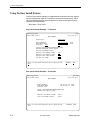
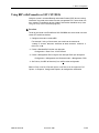
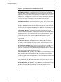
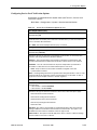
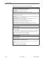
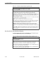
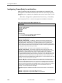
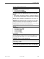
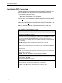
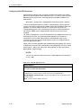
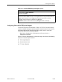
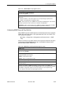
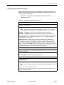
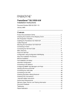
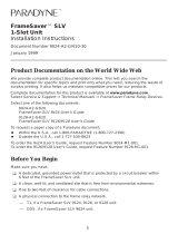
Using the Easy Install Feature
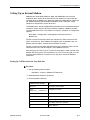
The Easy Install feature provides a straightforward installation menu that requires
minimal configuration to get the FrameSaver unit up and running quickly, and to
set up remote configuration and management via Telnet access from the NOC
(Network Operations Center).
Main Menu
→ Easy Install
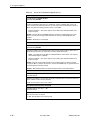
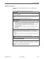
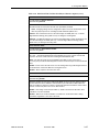
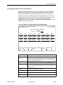
Easy Install Screen Example – T1 Interface
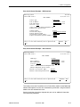
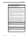
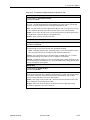
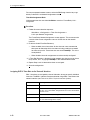
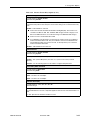
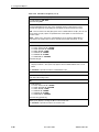
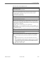
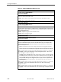
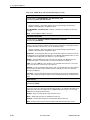
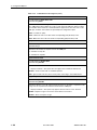
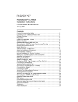
Easy Install Screen Example – T3 Interface
main/easy_install 9126
Device Name: Node A 11/01/2002 02:01
EASY INSTALL
Service Type: Frame Relay
Node IP Address: 000.000.000.000
Clear
Node Subnet Mask: 000.000.000.000
Clear
TS Access: DLCI
980
Create a Dedicated Network Management Link
Ethernet Management Options Screen
Time Slot Assignment Screen
Network 1 Line Framing Format: ESF
Network 1 Line Build Out (LBO): 0.0
Network 1 Line Coding Format: B8ZS
DS0 Base rate (Kbps) Nx64
--------------------------------------------------------------------------------
Ctrl-a to access these functions, ESC for previous menu M
ainMenu Exit
S
ave
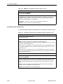
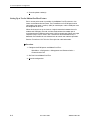
main/easy_install 9520-ILM
Device Name: Wasau 11/01/2002 12:01
EASY INSTALL
Node IP Address: 010.102.070.014 Clear
Node Subnet Mask: 255.255.255.000 Clear
TS Access: None
Create a Dedicated Network Management Link
Ethernet Port Options Screen
Network 1 Line Build Out(LBO): Short
Port 1 Line Build Out(LBO): Short
-------------------------------------------------------------------------------
Ctrl-a to access these functions, ESC for previous menu MainMenu Exit
Save

2. Basic Configuration
9000-A2-GB31-00 December 2002
2-3
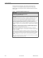
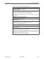
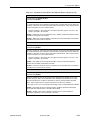
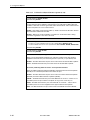
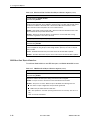
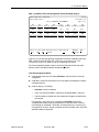
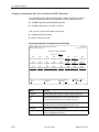
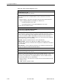
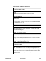
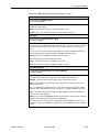
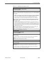
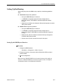
Easy Install Screen Example – DDS Interface
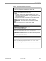
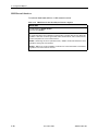
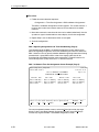
Easy Install Screen Example – DSL Interface
To remotely access the FrameSaver unit in Frame Relay mode, use the Dedicated
Network Management Link that was created during installation, using the Node IP
Address that was entered for the unit.
See the installation instructions shipped with your unit for additional information
and installation procedures.
main/easy_install 9623-SLV
Device Name: Node A 11/01/2002 02:03
EASY INSTALL
Service Type: Frame Relay
Node IP Address: 000.000.000.000
Clear
Node Subnet Mask: 000.000.000.000
Clear
TS Access: DLCI
980
Create a Dedicated Network Management Link
Ethernet Port Options Screen
Transmit Timing: Receive
DDS Line Rate (Kbps): Initialize From Network
Network Initiated DCLM: V.54 & ANSI
DSU Latching Loopback (64KCC): Enable
Require DSU Latching Loopback Preamble: Enable
--------------------------------------------------------------------------------
Ctrl-a to access these functions, ESC for previous menu M
ainMenu Exit
S
ave
main/easy_install 9783
Device Name: Node A 09/06/2002 04:02
EASY INSTALL
DSLAM Type: Paradyne
Node IP Address: 000.000.000.000 Clear
Node Subnet Mask: 000.000.000.000
Clear
TS Access: VPI,VCI
0 , 35
Create a Dedicated Network Management Link
Ethernet Management Options Screen
Network 1 DSL Line Rate (Kbps) AutoRate
Network 1 FRF.8 Encapsulation Mode Transparent
--------------------------------------------------------------------------------
Ctrl-a to access these functions, ESC for previous menu M
ainMenu Exit
S
ave

2. Basic Configuration
2-4 December 2002 9000-A2-GB31-00
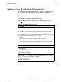
The menu structure and selections, and the features and functions of the
FrameSaver unit, are changed based upon the type of service being used.
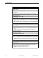
Table 2-1, Easy Install Configuration Options, describes the entries on the Easy
Install screens.
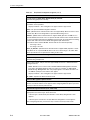
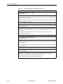
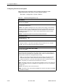
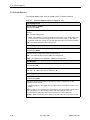
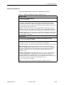
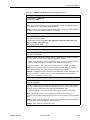
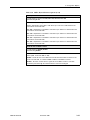
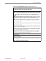
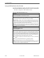
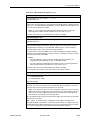
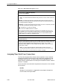
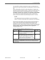
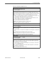
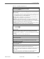
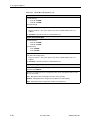
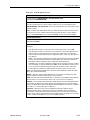
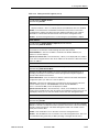
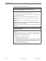
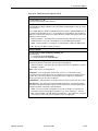
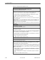
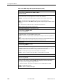
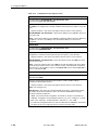
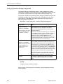
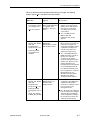
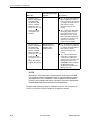
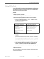
Table 2-1. Easy Install Configuration Options (1 of 7)
Service Type
Possible Settings: Frame Relay, Leased Line, PPP
Default Setting: [Depends on model]
Specifies the type of service to which the unit is to be connected.
Frame Relay – Frame Relay-aware mode, for connection to a frame relay service. This is
the default operational mode, and it is used to configure the FrameSaver unit in frame
relay mode so that frame relay parameters and SLV functionality can be set up.
If a 9123 unit is set to Leased Line, then changed to Frame Relay, Time Slot Discovery is
temporarily suspended until LMI communication is reestablished, and all frame
relay-related configuration options previously set up are restored, except for the Sync
Data Port Assignments. In this case, all port assignments set to S1Port-1 are converted to
FrameRly1 assignments on the Frame Relay Network 1 Assignment timeslot assignment
screen.
Leased Line – Leased-line mode, for connection to a standard leased-line service. This
mode provides a simple and straightforward screen to guide the installer during initial
installation, and to set up remote access to the unit.
When operating in leased-line mode, no frame relay-related statuses, performance
statistics, tests, configuration options, or control features are available; only physical layer
functions are available.
If the unit is set to Frame Relay then changed to Leased Line, all frame relay-related
screens and features are filtered so they are transparent to the user. All frame relay links,
DLCIs. and PVCs are preserved. For 9123 units, all Frame Relay Network 1 FrameRly1
time slot assignments are converted to S1Port-1 on the Sync Data Port Assignments
screen.
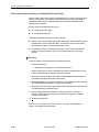
PPP – Point-to-Point Protocol mode. A single PPP circuit exists between Port1 and Net1.
Changing to or from PPP mode causes a reset.
Page is loading ...
Page is loading ...
Page is loading ...
Page is loading ...
Page is loading ...
Page is loading ...
Page is loading ...
Page is loading ...
Page is loading ...
Page is loading ...
Page is loading ...
Page is loading ...
Page is loading ...
Page is loading ...
Page is loading ...
Page is loading ...
Page is loading ...
Page is loading ...
Page is loading ...
Page is loading ...
Page is loading ...
Page is loading ...
Page is loading ...
Page is loading ...
Page is loading ...
Page is loading ...
Page is loading ...
Page is loading ...
Page is loading ...
Page is loading ...
Page is loading ...
Page is loading ...
Page is loading ...
Page is loading ...
Page is loading ...
Page is loading ...
Page is loading ...
Page is loading ...
Page is loading ...
Page is loading ...
Page is loading ...
Page is loading ...
Page is loading ...
Page is loading ...
Page is loading ...
Page is loading ...
Page is loading ...
Page is loading ...
Page is loading ...
Page is loading ...
Page is loading ...
Page is loading ...
Page is loading ...
Page is loading ...
Page is loading ...
Page is loading ...
Page is loading ...
Page is loading ...
Page is loading ...
Page is loading ...
Page is loading ...
Page is loading ...
Page is loading ...
Page is loading ...
Page is loading ...
Page is loading ...
Page is loading ...
Page is loading ...
Page is loading ...
Page is loading ...
Page is loading ...
Page is loading ...
Page is loading ...
Page is loading ...
Page is loading ...
Page is loading ...
Page is loading ...
Page is loading ...
Page is loading ...
Page is loading ...
Page is loading ...
Page is loading ...
Page is loading ...
Page is loading ...
Page is loading ...
Page is loading ...
Page is loading ...
Page is loading ...
Page is loading ...
Page is loading ...
Page is loading ...
Page is loading ...
Page is loading ...
Page is loading ...
Page is loading ...
Page is loading ...
Page is loading ...
Page is loading ...
Page is loading ...
Page is loading ...
Page is loading ...
Page is loading ...
Page is loading ...
Page is loading ...
Page is loading ...
Page is loading ...
Page is loading ...
Page is loading ...
Page is loading ...
Page is loading ...
Page is loading ...
Page is loading ...
Page is loading ...
Page is loading ...
Page is loading ...
Page is loading ...
Page is loading ...
Page is loading ...
Page is loading ...
Page is loading ...
Page is loading ...
Page is loading ...
Page is loading ...
Page is loading ...
Page is loading ...
Page is loading ...
Page is loading ...
Page is loading ...
Page is loading ...
Page is loading ...
Page is loading ...
Page is loading ...
Page is loading ...
Page is loading ...
Page is loading ...
Page is loading ...
Page is loading ...
Page is loading ...
Page is loading ...
Page is loading ...
Page is loading ...
Page is loading ...
Page is loading ...
Page is loading ...
Page is loading ...
Page is loading ...
-
 1
1
-
 2
2
-
 3
3
-
 4
4
-
 5
5
-
 6
6
-
 7
7
-
 8
8
-
 9
9
-
 10
10
-
 11
11
-
 12
12
-
 13
13
-
 14
14
-
 15
15
-
 16
16
-
 17
17
-
 18
18
-
 19
19
-
 20
20
-
 21
21
-
 22
22
-
 23
23
-
 24
24
-
 25
25
-
 26
26
-
 27
27
-
 28
28
-
 29
29
-
 30
30
-
 31
31
-
 32
32
-
 33
33
-
 34
34
-
 35
35
-
 36
36
-
 37
37
-
 38
38
-
 39
39
-
 40
40
-
 41
41
-
 42
42
-
 43
43
-
 44
44
-
 45
45
-
 46
46
-
 47
47
-
 48
48
-
 49
49
-
 50
50
-
 51
51
-
 52
52
-
 53
53
-
 54
54
-
 55
55
-
 56
56
-
 57
57
-
 58
58
-
 59
59
-
 60
60
-
 61
61
-
 62
62
-
 63
63
-
 64
64
-
 65
65
-
 66
66
-
 67
67
-
 68
68
-
 69
69
-
 70
70
-
 71
71
-
 72
72
-
 73
73
-
 74
74
-
 75
75
-
 76
76
-
 77
77
-
 78
78
-
 79
79
-
 80
80
-
 81
81
-
 82
82
-
 83
83
-
 84
84
-
 85
85
-
 86
86
-
 87
87
-
 88
88
-
 89
89
-
 90
90
-
 91
91
-
 92
92
-
 93
93
-
 94
94
-
 95
95
-
 96
96
-
 97
97
-
 98
98
-
 99
99
-
 100
100
-
 101
101
-
 102
102
-
 103
103
-
 104
104
-
 105
105
-
 106
106
-
 107
107
-
 108
108
-
 109
109
-
 110
110
-
 111
111
-
 112
112
-
 113
113
-
 114
114
-
 115
115
-
 116
116
-
 117
117
-
 118
118
-
 119
119
-
 120
120
-
 121
121
-
 122
122
-
 123
123
-
 124
124
-
 125
125
-
 126
126
-
 127
127
-
 128
128
-
 129
129
-
 130
130
-
 131
131
-
 132
132
-
 133
133
-
 134
134
-
 135
135
-
 136
136
-
 137
137
-
 138
138
-
 139
139
-
 140
140
-
 141
141
-
 142
142
-
 143
143
-
 144
144
-
 145
145
-
 146
146
-
 147
147
-
 148
148
-
 149
149
-
 150
150
-
 151
151
-
 152
152
-
 153
153
-
 154
154
-
 155
155
-
 156
156
-
 157
157
-
 158
158
-
 159
159
-
 160
160
-
 161
161
-
 162
162
-
 163
163
-
 164
164
-
 165
165
-
 166
166


Ask a question and I''ll find the answer in the document
Finding information in a document is now easier with AI
Related papers
-
 Paradyne FrameSaver SLV 9128-II Installation Instructions Manual
-
 Paradyne FrameSaver SLV 9126 Installation Instructions Manual
-
 Paradyne SLV Installation Instructions Manual
-
 Paradyne SLV Installation Instructions Manual
-
 Paradyne FrameSaver SLV 9820 Installation Instructions Manual
-
 Paradyne FrameServer SLV 9520-ILM Installation Instructions Manual
-
 Paradyne FrameSaver SLV 9626 Installation guide
-
 Paradyne framesaver 9623 Installation Instructions Manual
-
 Paradyne FrameSaver 9123 Installation Instructions Manual
-
 Paradyne FrameSaver SLV 9126 Installation Instructions Manual


Other documents
-
ADTRAN DSU 56_64 Owner's manual
-
Lucent Technologies FrameSaver SLV 9126 Installation Instructions Manual
-
Black Box SW556AE User manual
-
-
-
 Milliken Millwork Z022399L Installation guide
-
-
Bay Networks 6300 Ordering Manual
-
Aviosys IPPower 9820 Owner's manual
-
