Page is loading ...

1
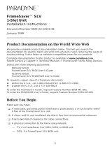
FrameSaver SLV 9128/9128-II
1-Slot Unit
Installation Instructions
Document Number 9128-A2-GN12-20
September 2000
Product Documentation on the World Wide Web
We provide complete product documentation online. This lets you search the
documentation for specific topics and print only what you need, reducing the waste of
surplus printing. It also helps us maintain competitive prices for our products.
Complete documentation for this product is available at www.paradyne.com.
Select
Library
→
Technical Manuals
→
FrameSaver Frame Relay Devices.
Select the following document:
9128-A2-GB20
FrameSaver SLV, Models 9126, 9128, and 9128-II,
User’s Guide
To order a paper copy of a Paradyne document:
Within the U.S.A., call 1-800-PARADYNE (1-800-727-2396)
Outside the U.S.A., call 1-727-530-8623
Package Checklist
Verify that your package contains the following:
FrameSaver SLV unit
Power cord with desktop 120 VAC power transformer.
T1 network cable
ISDN PRI or BRI cable, if applicable
FrameSaver SLV 9128/9128-II Quick Reference
(Document No. 9128-A2-GL10)
Be sure to register your warranty at www.paradyne.com/warranty.

2
Before You Begin
Make sure you have:
A dedicated, grounded power outlet that is protected by a circuit breaker within
6 feet of the FrameSaver SLV (service level verifier) unit.
A clean, well-lit, and ventilated site that is free from environmental extremes.
One-to-two feet of clearance for cable connections.
An asynchronous terminal or PC (personal computer).
If desired, an operable Ethernet LAN (Local Area Network) connection for access
by an NMS (Network Management System)
Configuration information for the FrameSaver unit being installed or replaced.
Appropriate cables:
— DSX cable
— Data port cables
— COM port-to-terminal or COM port-to-PC cable
— Modem cable
— Ethernet cable, if applicable
See the User’s Guide for additional information on:
Troubleshooting
Technical Specifications
Connectors, Cables, and Pin Assignments
Cables You May Need to Order
If connecting to a . . . Order a . . .
Model/Feature
Number
T1 line interface/connector
(For use in Canada
)
T1 line interface cable,
RJ48C-to-CA81A
3100-F1-510
LAN
(Model 9128 only)
Customer converter with a DB25
plug on one end and an 8-pin
modular jack on the other end, with
a custom 8-conductor cable and
LAN adapter
3100-F2-910
Contact your sales representative to order cables.

3
Safety Instructions
Read the
Important Safety Instructions
beginning on page 25.
Installing the Power Supply and Cord
1. Insert the power supply’s 4-prong plug into the POWER jack.
When inserting the plug at the rear of the FrameSaver unit, align the plug with the
notch above the POWER jack. Make sure the locking tab snaps securely into the
jack.
2.
DSX
COM
POWER
MODEM NETDBM
P
O
R
T
2
P
O
R
T
1
ENET
POWER
P
O
R
T
1
00-16841
Power Cord /
Transformer
Insert the 3-prong plug
into an AC outlet.
OK
ALM
The front panel
OK LED lights.
2.
3.
3-Prong
Grounded
AC Outlet
Locking
Tab on
Top
3.
4. Plug the power cord into the grounded power outlet and check the LEDs.
If any LEDs light, you have power. If not, refer to
Troubleshooting
in the User’s
Guide for possible explanations.
NOTE:
The rear panels shown in these instructions are for the Model 9128-II, which has
an Ethernet port. Except where noted, installation instructions are the same for the
Model 9128 without an Ethernet port.

4
Connecting the COM Port to an Asynchronous Terminal
A VT100-compatible asynchronous terminal or a PC providing VT100 terminal
emulation must be used to set up access to and management of the unit.
1. Configure the terminal or PC to be compatible with the FrameSaver unit:
– COM Port in use by your PC: COM1 or COM2.
– COM Port Baud Rate is set to 19.2 kbps.
– Character length is set to 8 data bits.
– Parity is set to none.
– Stop bit is set to 1.
– Flow Control is set to None.
2. Insert the DB25 end of the EIA-232 cable into the FrameSaver unit’s COM port.
DSX
COM
POWER
MODEM NETDBM
P
O
R
T
2
P
O
R
T
1
ENET
To Connect to a PC
or Async Terminal
COM
Port
00-16842
3. Insert the other end of the cable into the terminal or PC.
4. Tighten the screws on each side of the connector to secure the cable.
5. Press Enter on the keyboard to display the Main Menu.
If the Main Menu does not appear, recheck the terminal or PC settings (see
Step 1), or press the Enter key. Refer to
Troubleshooting
in the User’s Guide
for other possible explanations.
Verifying that Self-Test Passed
To verify that the unit passed its self-test, go to the System and Test Status screen.
Main Menu
→
Status
→
System and Test Status
The results of the self-test appears on the next screen line, under the screen title.
If any failure messages appear, reset the unit by disconnecting, then reconnecting the
power cord. The unit will perform the self-test again. If the failure reappears, call your
service representative for assistance.

5
A Quick Guide to Configuration
The FrameSaver unit should operate using the default (factory-set) configuration
options, with exception to the changes specified in these installation instructions. Refer
to the following table for help in navigating the menus.
Press the . . . To . . .
Esc key Go back one screen or menu level. To see a visual
representation of the menu levels, see
Menu Hierarchy
in
the Quick Reference.
Tab key, or
Up (↑), Down (↓),
Left (←) and Right (→)
Arrow keys
Move the cursor from one menu item to the next.
Enter or Return key Complete the menu or option selection.
Spacebar Display the next available setting when changing a
configuration option. All the available settings for an
option appears at the bottom of the screen.
As an example, follow these steps to go to the Configuration Edit/Display menu so you
can start setting up the unit.
To load a configuration for editing:
1. From the Main Menu, press the down arrow key twice so the cursor is on
Configuration.
2. Press Enter to display the Configuration menu. The Load Configuration From
menu appears.
3. Press Enter to select Current Configuration (the cursor is already on this
selection). The Configuration Edit/Display menu appears.
This sequence of steps would be shown as the menu selection sequence:
Main Menu
→
Configuration
To save a configuration option change:
1. Press Ctrl-a to switch to the function keys area at the bottom of the screen.
2. Type s or S (S
ave) and press Enter. The Save Configuration To menu appears.
3. Press Enter again to save your changes to the Current Configuration.
4. Press Esc until the Configuration Edit/Display menu reappears to continue
configuring the unit.
Press Ctrl-a, type m (M
ainMenu), and press Enter to return to the Main Menu.
In the sections that follow, only the minimum option changes required are included so
you will have a quick and trouble-free installation. See the configuration option tables in
the User’s Guide for more information about configuration options.

6
About the Installation Procedures
There are two methods for installing and setting up the FrameSaver unit.
One person can install and set up the unit. If this is the case, see
Full Installation
and Setup
.
An installer can physically install and set up access to the unit, and the network
operation center (NOC) can complete the setup. If this is the case, see
Minimal
Installation for Service Providers
on page 9.
Certain procedures are common to both the full installation and minimal methods.
These procedures are referenced in the full and minimal installation instructions
(starting with
Setting Up Local Management at the Central Site
on page 12). Refer
to them, as needed.
Full Installation and Setup
An Easy Install screen is provided to simplify installation and setup. It can be used
for the first part of the installation when one person is installing and setting up the unit
from beginning to end.
Easy Install Screen Example *
main/easy_install 9128-II
Device Name: Node A 5/26/2000 23:32
EASY INSTALL
Service Type: Frame Relay
Node IP Address: 000.000.000.000 Clear
Node Subnet Mask: 000.000.000.000
Clear
TS Access: DLCI
980
Create a Dedicated Network Management Link
Ethernet Port Options Screen
Time Slot Assignment Screen
Network 1 Line Framing Format: ESF
Network 1 Line Build Out (LBO): 0.0
Network 1 Line Coding Format: B8ZS
DS0 Base Rate (Kbps): Nx64
––––––––––––––––––––––––––––––––––––––––––––––––––––––––––––––––––––––––––––––
Ctrl-a to access these functions, ESC for previous menu M
ainMenu Exit
S
ave
*
The Service Type and Ethernet Port Options Screen only applies to the
Model 9128-II. DS0 Base Rate (Kbps) only applies to the Model 9128.

7
It is assumed that frame relay service is turned on at the site.
1. Select the Easy Install feature.
Main Menu
→
Easy Install
2. Enter the Node IP Address and Subnet Mask.
3. Set TS Access to DLCI, then select a DLCI on the network interface that
will be used for the troubleshooting access link.
4. Create a Dedicated Network Management Link, selecting a DLCI for the
management link at the Which DLCI would you like to Create a
Dedicated Network Management Link on? prompt, which will be used
by the NOC to access the unit.
5. For a FrameSaver SLV 9128-II that will use its Ethernet port, select the Ethernet
Port Options Screen and configure the following:
– Enable Interface Status. If the NMS will be on a different subnet than the unit,
enter Y
es at the Would you like to set the Node’s Default IP
Destination to Ethernet? prompt. Otherwise, enter N
o.
– If the IP Address and Subnet Mask are unique to the interface, enter them for
the port; otherwise, the Node IP Address and Subnet Mask will be used.
– Enter the Default Gateway Address; the IP Address that will be used for packets
without a route.
– Enable Proxy ARP if the unit will proxy for downstream FrameSaver units
learned via the proprietary RIP (Routing Information Protocol) feature.
– Press the Esc key to return to the Easy Install screen.
6. Configure the T1 network interface options to match the service provider’s settings.
7. S
ave the configurations.
8. Install the network cable (see
Connecting to the Network
on page 17). The
FrameSaver unit starts discovering DLCIs and network time slots (see
Automatic
Configuration
on page 12).

8
The remaining steps are optional, depending upon the application. They are performed
from the Main Menu.
9. If the unit will be enforcing CIR (Committed Information Rate) and EIR (Excess
Information Rate) on network frame relay links, enable Traffic Policing.
Main Menu
→
Configuration
→
System
→
Frame Relay and LMI
You can change other Frame Relay and LMI default settings, if necessary.
10. Configure each interface according to the local management interface (LMI) and
assigned line conditions supplied by the service provider.
Configuration
→
Network
→
Frame Relay
Configuration
→
Data Ports
→
Frame Relay
11. Set up SNMP local management (see
Setting Up Local Management at the Central
Site
on page 12).
12. Set up the modem, and the Call Directories if trap dial-out is desired (see
Setting
Up the Modem
on page 13).
13. If the unit is equipped with an ISDN DBM, set up the DBM (see
Setting Up the
ISDN DBM
on page 14).
14. If SNMP traps are wanted, set up managers, select the desired traps, and
configure trap dial-out if desired (see
Configuring SNMP Trap Managers and Trap
Dial-Out
on page 16).
15. S
ave the configurations.
16. Verify the entire path from the remote unit to the NMS is functioning (see
Verifying
the End-to-End Path
on page 18).
17. If the DSX-1 interface will be used, install the DSX-1 cable (see
Connecting to the
DSX
on page 19). Time slots for the DSX-1 interface will need to be assigned to
the network interface (see
Assigning DSX-1 Time Slots to the Network Interface
in
Configuration
of the User’s Guide).
18. Install the DTE cables (see
Connecting to the DTE (Router or FRAD)
on page 20).
19. Install the modem cable (see
Connecting the Modem
on page 21).
20. If the unit is equipped with an ISDN DBM, install the ISDN DBM cable (see
Connecting the ISDN
on page 22).
21. If the FrameSaver SLV 9128-II will use its Ethernet port for management, install
the Ethernet cable (see
Connecting to the Ethernet
on page 23).
22. Verify that data is being received (see
Verifying That Data is Being Received
on
page 23).
23. Verify that all PVCs, including Management PVCs, are configured; and see
whether the PVC is active or not (see
Checking PVC Connections
on page 24).
24. Verify the setup for backup, if applicable (see
Verifying that Data Can Be Passed
Between DBMs
on page 24).
The FrameSaver installation is complete.

9
Minimal Installation for Service Providers
In the following procedures, once the unit is installed and minimal configuration is
completed using the Easy Install feature, the NOC can complete and verify the setup.
For a Model 9128-II, see
Installing and Setting Up a Model 9128-II in Leased Line
Mode
on page 10 to install and set up the unit in Leased Line mode.
Physically Installing the Unit and Setting Up for Remote Access
It is assumed that frame relay service is turned on at the site. For a FrameSaver SLV
9128-II, this procedure is for setting up the unit in Frame Relay mode; the FrameSaver
SLV 9128 is always in Frame Relay mode.
1. Follow Steps 1 through 8 of
Full Installation and Setup
on page 7.
2. If the DSX-1 interface will be used, install the DSX-1 cable (see
Connecting to the
DSX
on page 19).
3. Install the DTE cables (see
Connecting to the DTE (Router or FRAD)
on page 20).
4. Install the modem cable (see
Connecting the Modem
on page 21).
5. If the unit is equipped with an ISDN DBM, install the ISDN DBM cable (see
Connecting to the ISDN
on page 22).
6. If a FrameSaver SLV 9128-II will use its Ethernet port for management, install the
Ethernet cable (see
Connecting to the Ethernet
on page 23).
Physical installation of the unit is complete; the NOC can now remotely access the unit
for additional configuration.

10
Installing and Setting Up a Model 9128-II in Leased Line Mode
It is assumed that frame relay service may not be available at the site and the unit will
be set up in Leased Line mode.
1. Select the Easy Install feature.
Main Menu
→
Easy Install
2. Change the Service Type to Leased Line.
3. Set TS Access to DLCI, then select a DLCI on the network interface that will
be used for the troubleshooting access link.
4. If the Ethernet port will be used, select the Ethernet Port Options Screen and
configure the following:
– Enable Interface Status. If the NMS will be on a different subnet than the unit,
enter Y
es at the Would you like to set the Node’s Default IP
Destination to Ethernet? prompt. Otherwise, enter N
o.
– If the IP Address and Subnet Mask are unique to the interface, enter them for
the port; otherwise, the Node IP Address and Subnet Mask will be used and can
be entered when you return to the Easy Install screen.
– Enter the Default Gateway Address; the IP Address that will be used for packets
without a route.
– Enable Proxy ARP if the unit will proxy for downstream FrameSaver units
learned via the proprietary RIP (Routing Information Protocol) feature.
– Press the Esc key to return to the Easy Install screen.
5. Select the Time Slot Assignment screen to manually assign the user data port to
network interface time slots (see
Assigning Time Slots/Cross Connections
in
Configuration
of the User’s Guide).
6. Configure the T1 network interface options to match the service provider’s settings.
7. S
ave the configurations.
8. Install the network cable (see
Connecting to the Network
on page 17).
9. If the DSX-1 interface will be used, install the DSX-1 cable (see
Connecting to the
DSX
on page 19).
10. Install the DTE cables (see
Connecting to the DTE (Router or FRAD)
on page 20).
11. Install the modem cable (see
Connecting the Modem
on page 21).
12. If the unit is equipped with an ISDN DBM, install the ISDN DBM cable (see
Connecting to the ISDN
on page 22).
13. If the Ethernet port will be used for management, install the Ethernet cable (see
Connecting to the Ethernet
on page 23).
Physical installation of the unit is complete; the NOC can now remotely access the unit
for additional configuration.

11
Completing Setup of the Unit From the NOC
1. Access the remote FrameSaver unit.
– For a unit installed using the procedure in
Physically Installing the Unit and
Setting Up for Remote Access
on page 9
,
access the unit using the dedicated
management link, using the Node IP Address that was entered.
– For a Model 9128-II installed using the procedure in
Installing and Setting Up a
Model 9128-II in Leased Line Mode
on page 10, ping the FrameSaver unit
five times within five seconds on the troubleshooting access link. The unit
automatically configures the TS Access DLCI as a non-multiplexed
management DLCI and assumes the IP address on this management link is the
same as the destination address of the ping.
2. Configure specific frame relay options, like CIR (committed information rate), and
any other configuration options requiring input or changes from the default settings.
3. Configure each interface according to the local management interface (LMI) and
assigned line conditions supplied by the service provider.
Configuration
→
Network
→
Frame Relay
Configuration
→
Data Ports
→
Frame Relay
4. If SNMP traps are wanted, set up managers, select the desired traps, and
configure trap dial-out if desired (see
Configuring SNMP Trap Managers and Trap
Dial-Out
on page 16).
5. Set up the modem and, if trap dial-out is desired, the Call Directories (see
Setting
Up the Modem
on page 13).
6. If the unit is equipped with an ISDN DBM, set up the DBM (see
Setting Up the
ISDN DBM
on page 14).
7. S
ave the configurations.
8. Verify the entire path from the remote unit to the NOC NMS is functioning (see
Verifying the End-to-End Path
on page 18).
9. Verify that data is being received (see
Verifying That Data is Being Received
on
page 23).
10. Verify that all PVCs, including Management PVCs, are configured; and see
whether the PVC is active or not (see
Checking PVC Connections
on page 24).
11. Verify the setup for backup, if applicable (see
Verifying that Data Can Be Passed
Between DBMs
on page 24).
The FrameSaver installation is complete.

12
Setting Up Local Management at the Central Site
1. Create a DLCI for the data port.
Configuration
→
Data Ports
→
DLCI Records
2. Save the configuration.
3. Create a Management PVC using the data port DLCI just created.
Configuration
→
Management and Communication
→
Management PVC
Minimally, enter the following options:
– Name for the management PVC
– Interface IP Address and Subnet Mask, if different from the Node’s
– Primary Link for this Management PVC (the user data port)
– Primary DLCI (i.e., the data port DLCI)
4. S
ave the configuration.
Automatic Configuration
The FrameSaver unit provides several automatic configuration features. Frame Relay
Discovery and configuration is one of these features.
Main Menu
→
Auto-Configuration
The default discovery mode is 1MPort. In this mode, for each DLCI discovered on the
network, the unit creates a network interface DLCI containing two EDLCIs (embedded
DLCIs – one for Port-1 data and the other for management), a Port-1 DLCI with the
same number, and a management PVC, then cross-connects them.
NOTE:
When auto-configuration creates a multiplexed DLCI, but a standard DLCI is
needed, change the DLCI to Standard from the network DLCI Records screen:
Configuration
→
Network
→
DLCI Records
Other modes can be selected. See
Setting Up Automatic Configuration
in
Configuration
of the User’s Guide for information about other modes and how the Frame Relay
Discovery Mode can be changed.
No automatic configuration occurs until the network cable is connected. If you do not
want management links configured or automatic configuration, change the default
setting for the Frame Relay Discovery feature.
Time Slot Assignment
Network time slots are discovered automatically when Time Slot Discovery is enabled
(the default setting) on the Frame Relay Network 1 Assignments screen. This feature
can be disabled if you want to manually configure time slots.
See
Assigning Time Slots/Cross Connections
in
Configuration
of the User’s Guide for
additional information about this feature.

13
Setting Up the Modem
The unit has an integral modem for remote management. It is already set up for dial-in
access to the unit, with Port Use set to Terminal.
If using the modem for dialed IP network connectivity (SNMP, Telnet, FTP, or
trap dial-out):
1. Select Modem Port.
Configuration
→
Management and Communication
→
Modem Port
2. Minimally, change Port Use to Net Link, and assign the interface’s IP Address and
Subnet Mask if it is different from the Node’s. Change Link Protocol to SLIP, if
necessary (PPP is the default setting).
3. S
ave the configuration.
Setting Up Call Directories if Trap Dial-Out Is Desired
1. Set up directory phone numbers.
Main Menu
→
Control
→
Modem Call Directories
2. Select Directory Number A (for Alarm).
3. Enter the phone number(s). Valid characters include:
– ASCII text
– B for blind dialing
– W for wait for dial tone
– P for pulse dialing unless B specified
– T for tone dialing unless B specified
– Space, underscore ( _ ), comma (,) for a 2-second pause, and dash (–)
readability characters
4. S
ave the phone number(s).
Setting Up to Use the Modem PassThru Feature
The Modem PassThru feature allows access to the router via a dial-up connection to
the unit. When this feature is set up and active, a logical connection between the unit’s
modem and COM ports is made, and data received over the modem port is transmitted
out the COM port to the router’s auxiliary (AUX) serial port. When an escape sequence
(minus, minus, minus) is detected, the FrameSaver unit switches back to normal user
interface operation. If this feature will be used, the COM port must be configured for
that use.
1. Configure the COM port to use Modem PassThru.
Main Menu
→
Configuration
→
Management and Communication
→
Communication Port
2. Set Port Use to Modem PassThru.
3. S
ave the configuration.

14
Setting Up the ISDN DBM
FrameSaver SLV 9128s and 9128-IIs may be equipped with an ISDN PRI or BRI DBM.
These instructions are for units with ISDN backup capability.
The following guidelines apply:
Central site configuration guidelines:
– Set up the ISDN DBM physical interface.
– If a BRI DBM, change the Automatic Backup Configuration to
Multi_Site_Backup. (A PRI DBM is already configured for multisite backup.)
– Modify the Link Profile(s) that Automatic Backup Configuration created to add a
phone number.
Remote site configuration guidelines:
– Set up the ISDN DBM physical interface.
– If a PRI DBM, change the Automatic Backup Configuration to
Single_Site_Backup. (A BRI DBM is already configured for single-site backup.)
– Modify the HQ_Site Link Profile that Automatic Backup Configuration created to
add a phone number.
– Set the criteria by which automatic backup will take place.
Setting Up the DBM Physical Interface
1. Configure the DBM interface.
Main Menu
→
Configuration
→
ISDN
→
Physical
2. Minimally, set the following configuration options:
– Interface Status is set to Enable.
– Local Phone Number 1 is entered, plus the following:
FrameSaver Unit with BRI FrameSaver Unit with PRI
Configure the B-channels:
Service Profile ID1 (SPID)
Service Profile ID2 (SPID)
Local Phone Number 2
Configure T1 physical characteristics
to match the service provider’s
settings.
3. Save the configuration and return to the ISDN menu.

15
Setting Up Automatic Backup Configuration
The Automatic Backup Configuration feature, included on the Auto-Configuration menu,
is used to automatically create alternate DLCI records and PVC connections on the
ISDN DBM (backup) interface.
This feature is already set up in FrameSaver units with a DBM.
Single_Site_Backup is the default for a BRI DBM.
Multi_Site_Backup is the default for a PRI DBM.
See the User’s Guide for additional information.
Modifying ISDN Link Profiles
1. Select Link Profiles, then Modify.
The FrameSaver unit automatically configures an ISDN Link Profile on the first
ISDN link, with HQ_Site as the Link Name. For subsequent ISDN Link Profiles,
select N
ew.
2. Add a name and phone number to the ISDN Link Profile(s) created by Automatic
Backup Configuration.
– Name for the destination entered (e.g., Tampa). The default setting of HQ_Site.
– Phone numbers entered:
For Originating a Backup Call For Answering a Backup Call
Outbound and Alternate Outbound
phone numbers
Valid characters include:
Numbers (0–9)
Special characters * and #
Spaces
Parentheses ( )
Inbound Calling ID1 and ID2
These are the phone numbers
of units from which calls will be
accepted.
Valid characters include:
Numbers (0–9)
NOTES:
Remember to include local dial-out numbers (i.e., 9, then the number).
For every originating (outbound) phone number entered, an answering
(inbound) phone number must be entered at the far end, and vice versa.
– Maximum Link Rate is changed, if necessary. The default setting is 64 kbps.
3. S
ave the configuration.

16
Setting the Criteria for Automatic Backup
1. Enable Auto Backup.
Main Menu
→
Configuration
→
Auto Backup Criteria
When a failure occurs, the unit automatically enables the Alternate Link and traffic
is rerouted over the backup (alternate) interface.
2. Specify When Auto Backup Allowed – Always or Restrict. If Restrict is selected,
specify the days and hours of the week during which automatic backup can take
place.
3. S
ave the configuration.
Configuring SNMP Trap Managers and Trap Dial-Out
Once the FrameSaver unit is connected to the network, SNMP trap managers, SNMP
traps, and trap dial-out can be configured.
1. Select SNMP Traps.
Main Menu
→
Configuration
→
Management and Communication
→
SNMP Traps
2. Configure the following:
– Enable SNMP Traps.
– Identify the total Number of Trap Managers.
– Specify the IP address of the NMS(s) to which traps will be sent.
– Specify the network Destination for the Trap Manager(s).
– Select desired trap categories.
– Enable Trap Dial-Out, if desired.
3. S
ave the configuration.
4. Return to the Main Menu.

17
Connecting to the Network
1. Insert the 8-pin connector of the RJ48C network cable into the network interface.
2. Insert the other end of the cable into the RJ48C modular jack.
DSX
COM
POWER
MODEM NETDBM
P
O
R
T
2
P
O
R
T
1
ENET
00-16843
RJ48C
Jack
NOTE:
After connecting the network cable, wait a few minutes to allow
Auto-Configuration a chance to discover the frame relay characteristics
and DLCIs.
3. Verify that the Network signal (SIG) LED is green, and that the Network
out-of-frame (OOF) and alarm (ALM) LEDs are off. If so, the network interface is
set up correctly and is operational. If not, make sure both ends of the network
cable are properly seated.
The FrameSaver SLV 9128-II has a FR (Frame Relay) LED. It will be green when
the unit is operating in Frame Relay mode and LMI is up, yellow when the unit is
operating in Frame Relay mode and LMI is down, and it will be off when the unit is
operating in Leased Line mode.
4. Check Health and Status messages in the left column of the System and Test
Status screen.
Main Menu
→
Status
→
System and Test Status
If LMI Down, Network appears for more than three minutes, or any other
network-related status message appears, refer to the status information in
Operation and Maintenance
of the User’s Guide for possible reasons for the
messages and what can be done to resolve the problem.
If the unit does not have ISDN backup capability, proceed to
Configuring SNMP Trap
Managers and Trap Dial-Out
on page 16.

18
Verifying the End-to-End Path
After installation of a remote site unit, run an IP Ping test to ping the NMS at the central
site and verify that the entire path from the remote unit to the NMS is functioning. To run
the IP Ping test, NMS trap managers must have been configured for the remote unit.
One of those trap managers must be the central site NMS.
1. Select the IP Ping test.
Main Menu
→
Test
→
IP Ping
2. Enter the IP Address of the device being pinged, then select Start.
NOTE:
When running tests, the cursor is positioned over the Start command. Press
Enter to start the test. Stop is displayed while the test is running. Press Enter
again to issue the Stop command.
– While the test is running, In Progress... appears in the Status field.
– When the test is finished, Alive. Latency =
nn
ms should appear as the
Status (
nn
being the amount of time the test took in milliseconds).
If any other message is displayed, additional testing will be required. See
Device
Messages
in
Operation and Maintenance
of the User’s Guide for information
about IP Ping-related messages.

19
Connecting to the DSX
1. Connect the DB15 end of the DSX cable to the DSX-1 interface.
2. Connect the other end of the cable to the CPE (customer premises equipment,
like a PBX).
3. Tighten the screws on each side of the connector to secure the cable.
DSX
COM
POWER
MODEM NETDBM
P
O
R
T
2
P
O
R
T
1
ENET
00-16844
PBX
4. Verify that the DSX signal (SIG) LED is green, and that the DSX out-of-frame
(OOF) and alarm (ALM) LEDs are off. If so, the DSX interface is set up correctly
and is operational. If not, make sure both ends of the DSX cable are properly
seated.
When ALM is on, contact the service provider.
5. Check Health and Status messages in the left column of the System and Test
Status screen.
Main Menu
→
Status
→
System and Test Status
If any DSX-1 messages appear, refer to the status information in
Operation and
Maintenance
of the User’s Guide.

20
Connecting to a DTE (Router or FRAD)
1. Connect one end of the DTE’s V.35 cable to the data port.
2. Plug the other end of the cable into the DTE.
3. Tighten the screws on each side of the connector to secure the cable.
DSX
COM
POWER
MODEM NETDBM
P
O
R
T
2
P
O
R
T
1
ENET
00-16845
DTE
4. Repeat Steps 1–4 of this procedure for Port-2.
5. Verify that the Port OK LED is on. If not, make sure both ends of the cable are
properly seated and secured. Then, check the DTE; RTS or DTR could be down
on the DTE.
– The FrameSaver SLV 9128 has a Port OK LED for each port.
– The FrameSaver SLV 9128-II has one Port OK LED for both ports. If either port
is enabled and active, the LED is on. If both ports are enabled and one of the
ports is inactive, the LED is off.
6. Check Health and Status messages in the left column of the System and Test
Status screen for messages.
Main Menu
→
Status
→
System and Test Status
– If System Operational appears, the port interface is set up correctly and
is operational.
– If not, refer to
Status Information
in the User’s Guide.
NOTE:
When any error conditions are detected, a status message appears along the
bottom right corner of the screen.
1/30