Page is loading ...

Multicast Video Distribution System
MVDS X-1
Installation / User's Guide


- Copying all or a part of this manual without our permission is prohibited.
- The contents of this manual may be changed without advance notice.
- Please note that the actual screens may vary from the examples in this manual.
This can be caused by dierent versions of operating systems on the PC,
upgrades, etc.
- This manual has been edited very carefully. However, Silex Technology, Inc. is
not responsible for any mistakes included in this manual or any damages, direct
or indirect, arising from the use of this manual.
- Information and descriptions contained herein are the property of Silex
Technology, Inc. Such information and descriptions may not be copied,
disseminated, or distributed without the express written consent of Silex
Technology, Inc. This publication is subject to change without notice.
About notation
Thank you very much for purchasing Silex's MVDS X-1, the Multicast Video
Distribution System (this product).
This manual provides how to setup and use this product.
Introduction
- Microsoft and Windows are either registered trademarks or trademarks of
Microsoft Corporation in the United States and/or other countries.
- Ethernet is a registered trademark of Xerox Corporation.
- Other brand or product names are registered trademarks or trademarks of their
respective owners.
About trademarks
©
Copyright 2008 Silex Technology, Inc.


Index
Product Overview..................................................... 1
1.1 About this product ........................................................................................2
1.2 Specication.....................................................................................................4
1.2.1 Hardware specication.....................................................................................................................4
1.2.2 Software specication......................................................................................................................6
1.2.3 Interface specication ......................................................................................................................7
1.2.4 Notes on the radio wave..................................................................................................................8
1.3 Network composition ..................................................................................9
1.4 Parts and function
.......................................................................................
12
Installation .............................................................. 15
2.1 Before you begin ......................................................................................... 16
2.1.1 Necessary items ...............................................................................................................................16
2.1.2 Create environment for setup ....................................................................................................17
2.2 Congure this product .............................................................................. 19
2.2.1 Assign IP address
.............................................................................................................................
19
2.2.2 Congure via Web browser
..........................................................................................................
21
Host name / Password conguration............................................................................................. 22
Network conguration ........................................................................................................................ 23
Adjusting a screen image (at transmitter)
....................................................................................
25
Adjusting a screen image (at receiver(s))......................................................................................27
2.3 Hardware installation................................................................................. 28
2.3.1 Connect to a wired network
........................................................................................................
28
2.3.2 Connect to a wireless network...................................................................................................29
Vertical convergence angle and minimum distance................................................................30
Vertical coverage and Line-of-sight
................................................................................................
31

Monitor and Maintenance ..................................... 33
3.1 Front panel..................................................................................................... 34
3.1.1 Menu structure and how to use it.............................................................................................34
3.1.2 Functions available in each menu.............................................................................................36
Initial screen (Level:0)...........................................................................................................................36
SERVICE ACTIVITY..................................................................................................................................37
CONNECTION STAT
................................................................................................................................
38
DEVICE INFO............................................................................................................................................ 39
ADMIN MODE MENU............................................................................................................................ 40
3.2 Web interface................................................................................................ 46
3.2.1 Status ................................................................................................................................................... 48
General......................................................................................................................................................48
Network
....................................................................................................................................................
49
Video/Audio/Data
.................................................................................................................................
50
3.2.2 Conguration....................................................................................................................................51
General......................................................................................................................................................51
Network ....................................................................................................................................................52
Video/Audio/Data (at transmitter) .................................................................................................. 54
Video/Audio/Data (at receiver).........................................................................................................57
Static Node (at transmitter) ...............................................................................................................59
Static Node (at receiver)...................................................................................................................... 60
Dynamic Node (at transmitter).........................................................................................................61
Dynamic Node (at receiver) ...............................................................................................................62
3.2.3 Tools
.....................................................................................................................................................
63
Common...................................................................................................................................................63
Video/Audio (at transmitter) ............................................................................................................. 64
Video/Audio (at receiver)....................................................................................................................65
Appendix................................................................A-1
A-1 Conguration item list............................................................................ A-2

1.Product Overview
1
Product Overview
1

2
MVDS X-1 User's Guide
1.1 About this product
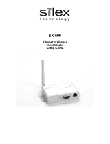
MVDS stands for "Multicast Video Distribution System", which allows to distribute video
or audio data from Player (e.g. PC, DVD player, etc) to Display (e.g. TV, Monitor, etc) by IP
Multicast.
The MVDS consists of transmitter and receiver(s). The transmitter is connected to Player
and the receiver(s) are connected to Display. Transmitter encodes the signal output
from the Player (e.g. video, audio, etc.) and distributes its codec data to receiver(s) in
real time, and the receiver(s) decodes and outputs it on Display.
A/D
D/A
Encode
Decode
IP Network
X-1T X-1R
Audio
Vi
deo
Serial

1.Product Overview
3
Feature
Video and Audio control
- Adopts JPEG2000 codec. High compression with less image degradation available
- Audio codec: 16bit stereo PCM (Sampling rate: 32KHz)
- Screen size supports WXGA (1280x768)
- Up to 30fps of frame rate
- Synchronization function for video and audio (Lip-sync)
Network control
-
Allow simultaneous distribution to multiple receivers by multicast (up to 32 receivers)
- Time correction between transmitter and receivers allows simultaneous
output among receivers
- Support Wired LAN(10Base-T/100Base-TX) and Wireless LAN (IEEE802.11a/g:
Infrastructure/ad hoc mode)
Others
- Support 1ch of serial port for remote monitoring and control
- Various congurations are available on embedded Web page
- Switch the transmitter automatically at a specied interval
- Connection and communication status can be veried at LCD (Transmitter only)
- Receiver's ID (host name) can be set by rotary switch (Receiver only)

4
MVDS X-1 User's Guide
1.2.1 Hardware specication
Hardware specication is as follows:
CPU TOSHIBA TX4939 400MHz (32/64bit MIPS)
RAM 128MB DDR
ROM 8MB
Interface Video Analog RGB D-SUB15 x 1
Audio 16bit Stereo line in / out (Mini Jack)
Serial RS-232C (D-SUB9) x 1
Ethernet 10BASE-T/100BASE-TX Auto detection (RJ-45) x 1
Wireless IEEE802.11a/b/g mini PCI module x 1 (SX-10WAG)
Power AC adapter (Operating voltage 15V)
LCD 16 Characters x 2 Lines (Transmitter only)
LED 4 Front Side
"Power" / "Status" / "Wireless" / "Ether"
2 Back Side
RJ-45 "Link" / "Status"
Push Switch 4 Front Side
"MEMU" / "-" / "+" / "SET"
Rotary Switch 2 (Receiver only)
1.2 Specication

1.Product Overview
5
This device complies with Part 15 of the FCC Rules. Operation is subject to the
following two conditions: (1) This device may not cause harmful interference, and
(2) this device must accept any interference received, including interference that
may cause undesired operation.
FCC Notices
This equipment has been tested and found to comply with the limits for a Class
B digital device, pursuant to Part 15 of the FCC Rules. These limits are designed
to provide reasonable protection against harmful interference in a residential
installation. This equipment generates, uses, and can radiate radio frequency
energy and, if not installed and used in accordance with the instructions, it
may cause harmful interference to radio communications. However, there is
no guarantee that interference will not occur in a particular installation. If this
equipment does cause harmful interference to radio or television reception, which
can be determined by turning the equipment o and on, the user is encouraged
to try to correct the interference by one or more of the following measures:
- Reorient or relocate the receiving antenna.
- Increase the separation between the equipment and receiver.
- Connect the equipment into an outlet on a circuit dierent from that to
which the receiver is connected.
- Consult the dealer or an experienced radio/TV technician for assistance.

6
MVDS X-1 User's Guide
1.2.2 Software specication
Software specication is as follows:
Protocol
TCP/IP Network Layer ARP , RARP , IPv4 , ICMP
Multicast : IPv4 Organization Local Scope 239.192.0.0/14
Transport Layer TCP , UDP
Application Layer TELNET , BOOTP , DHCP , HTTP , UPnP ,
JCP (proprietary #19541) ,
RTP (proprietary #50001 - #65535) ,
MVDS Announcement Protocol (proprietary #50000)
SX-RPC (proprietary via HTTP/RTP)
Others FLDP For rmware version up
Other
Serial Data Transfer Protocol Proprietary

1.Product Overview
7
1.2.3 Interface specication
Interface specication is as follows:
Video
Interface Analog RGB (15pin Dsub)
Codec JPEG2000
Resolution 1280 x 768 pixel (WXGA)
Flame rate 30 fps (MAX)
Conguration Video Adjustment(Contrast , Bright , Position etc…)
Others Startup screen, Stop signal screen, Maintenance screen
(Display a still image specied in each mode.)
Audio
Interface Stereo mini jack
Codec 16bit PCM
Sampling rate 32 (KHz)
Serial Data
Baud rate 300 , 600 , 1200 , 2400 , 4800 , 9600 , 14400 , 19200 , 38400 , 57600 , 115200 (bps)
Bit length 8 , 7 (bit)
Stop bit 1 , 2 (bit)
Parity NONE , EVEN , ODD
Flow Control NONE , XON/XOFF , RTS/CTS
Timeout 50 to 1000(ms)

8
MVDS X-1 User's Guide
1.2.4 Notes on the radio wave
Do not use this product near the following equipment or places.
- Microwave, scientic instruments, pacemaker or other medical equipment.
- Licensed radio station in a factory.
- Small power radio station (a non-licensed radio station).
Wireless Equipment for 2.4GHz and 5GHz band
This frequency band is used by a microwave, industry, science, medical equipment
and licensed in room or low power (non licensed) radio stations.
- Before you use this equipment, verify that it will not interfere with other
broadcasting.
- If interference happens, stop using the equipment or change the band.
Contact us to discuss ways of avoiding interference (example: create the wall).
The following equipment may use the same band. If you use this product near
this equipment, the radio waves from this product and the following devices may
interfere with each other.
A cellular phone, TV, and radio use dierent radio bands than our product.
Generally if they are used near this product, it will not cause a problem. However,
when near this product, sound or image noise can happen.
If there is reinforced concrete/metal between wireless devices, they may not
connect.
This product can connect through wood or glass, but can have trouble
communicating through reinforced concrete/metal.
Do not use this product near a cellular phone, TV or Radio.

1.Product Overview
9
1.3 Network composition
A MVDS network is composed of one MVDS transmitter and 32 MVDS receivers
(at maximum). In each group, a video or audio data are distributed in multicast (or
unicast).
As for network interface, both Wired and Wireless LAN ports are supported. Since
MVDS transmitter and receivers exchange their status each other regularly, you
can easily install and congure this product as well as support various network
environment.
- UDP is used as a protocol for data distribution and information exchange.
- Not available via an Internet.
Wireless system - Network composition for Infrastructure mode
The player (e.g. PC, DVD player, etc.) outputs data (e.g. video, audio, serial data,
etc.) to MVDS transmitter. The transmitter captures and sends them to Access Point
via a wired LAN. These data are distributed to the MVDS receivers being connected
to the Access Pint in Infrastructure mode.
{
AV Cable
Ethernet (100Base, PLC)
Wireless (IEEE802.11a/g)

10
MVDS X-1 User's Guide
Wireless system - Network composition for Ad-Hoc mode
The player (e.g. PC or DVD player, etc.) outputs data (e.g. video, audio, serial data,
etc.) to MVDS transmitter. The transmitter captures and sends them to the MVDS
receivers being connected to the transmitter in Adhoc mode.
Network composition for wired connection
The player (
e.g.
PC or DVD player, etc) outputs data (
e.g.
video, audio, serial data,
etc.) to MVDS transmitter. The transmitter captures and distributes it to the MVDS
receivers being connected to an Ethernet LAN.
{
AV Cable
Wireless (IEEE802.11a/g)
AV Cable
Ethernet (100Base, PLC)

1.Product Overview
11
Network composition for wired/wireless connection mix
If the wired/wireless system are mixed, you can support wider variety of
environment.
{
AV Cable
Ethernet (100Base, PLC)
Wireless (IEEE802.11a/g)

12
MVDS X-1 User's Guide
1.4 Parts and function
The name of each part and the function are explained below:
Front
Transmitter
Push button Description
MENU Go into LCD menu from initial screen.
Return to initial screen from LCD top menu.
Go back to higher level in LCD menu.
Start a factory default conguration when this button and [SET] button are
pushed together while turning on this product.
- Return to previous option in LCD menu.
Select a value to set.
+ Move to next option in LCD menu.
Select a value to set.
SET Go into the selected menu in LCD menu.
Enable the selected value.
Start a factory default conguration when this button and [MENU] button are
pushed together while turning on this product.

1.Product Overview
13
LED (both Transmitter and Receiver)
LED Description
POWER OFF: Powered o or being on boot process.
ON: Powered on (Normal status)
STATUS Blink: Blink every time when codec of 1 frame data is complete.
ON: Factory default conguration using push buttons is complete.
WIRELESS OFF: Wireless communication is disabled.
Blink: Wireless communication is not established. (Detecting AP or other node,
or unable to connect for wireless conguration mismatch).
ON: Wireless communication is established.
ETHER OFF: Not connected to wired LAN (Not linked)
ON: Connected to wired LAN (Being linked)
Receiver
Push button Description
MENU Start a factory default conguration when this button and [SET] button are
pushed together while turning on this product.
- Not use.
+ Not use.
SET Start a factory default conguration when this button and [MENU] button are
pushed together while turning on this product.

14
MVDS X-1 User's Guide
Back
Both Transmitter and Receiver
Part Description
DCIN 15V1A AC connector (15V 1A)
* In case of X-1ER, AC power can be supplied via internal DC connector.
ETHER Ethernet interface (RJ45)
RS232C Serial interface (9pin Male)
AUDIO Audio interface (3.5mm mini)
ANALOG RGB RGB interface (D-Sub15pin)
Antenna SMA Connector
(Connect the antenna to either or both of the connectors.)
Ethernet LED Description
Backside
(Ethernet Connector)
Green
OFF: Not connected to a wired LAN (Not linked)
ON: Connected to a wired LAN (Linked)
Orange
Blink: Blink when receiving a packet via wired or wireless LAN.
Flash: Data error in a conguration area
ROM/RAM check error
LED (both Transmitter and Receiver)
/