Page is loading ...


i
Warnings and Cautions:
Installation Instructions
Secure Racking
If Secure Racked units are installed in a closed or multi-unit rack assembly, they may
require further evaluation by Certification Agencies. The following items must be
considered.
1. The ambient within the rack may be greater than room ambient. Installation
should be such that the amount of air flow required for safe operation is not
compromised. The maximum temperature for the equipment in this environment is
60°C. Consideration should be given to the maximum rated ambient.
2. Installation should be such that a hazardous stability condition is not achieved due
to uneven loading.
Input Supply
1. Check nameplate ratings to assure there is no overloading of supply circuits that
could have an effect on overcurrent protection and supply wiring.
2. When installing -48 VDC rated equipment, it must be installed only per the
following conditions:
A. Connect the equipment to a 48 VDC supply source that is electrically isolated
from the alternating current source. The 48 VDC source is to be connected to
a 48 VDC SELV source.
B. Input wiring to terminal block must be routed and secured in such a manner
that it is protected from damage and stress. Do not route wiring past sharp
edges or moving parts.
C. A readily accessible disconnect device, with a 3 mm minimum contact gap,
shall be incorporated in the fixed wiring.
Grounding
Reliable earthing of this equipment must be maintained. Particular attention should
be given to supply connections when connecting to power strips, rather than direct
connections to the branch circuit.
No Serviceable Parts Inside; Authorized Service Personnel Only
Do not attempt to repair or service this device yourself. Internal components must be
serviced by authorized personnel only.
• ShockHazard-DoNotEnter
• LithiumBattery
CAUTION:Dangerofexplosionifbatteryisincorrectlyreplaced.Replace
onlywithsameorequivalenttyperecommendedbythemanufacturer.
Discardusedbatteriesaccordingtothemanufacturer'sinstructions.

ii
Warnings and Cautions
Disconnect Power
If any of the following events are noted, immediately disconnect the unit from the outlet
and contact qualified service personnel:
1. If the power cord becomes frayed or damaged.
2. If liquid has been spilled into the device or if the device has been exposed to rain
or water.
Disconnect Power Before Servicing
Before attempting to service or remove this unit, please make certain to disconnect the
power supply cable from the power source.
Modem Cables
CAUTION: To reduce the risk of fire, use only No. 26 AWG or larger (e.g., 24 AWG) UL
Listed or CSA Certified Telecommunication Line Cord.

iii
Agency Approvals
FCC Part 15 Regulation
This equipment has been tested and found to comply with the limits for a Class A digital
device, pursuant to part 15 of the FCC Rules. These limits are designed to provide
reasonable protection against harmful interference when the equipment is operated
in a commercial environment. This equipment generates, uses, and can radiate radio
frequency energy and, if not installed and used in accordance with the instruction
manual, may cause harmful interference to radio communications. Operation of this
equipment in a residential area is likely to cause harmful interference in which case the
user will be required to correct the interference at his own expense.
This device complies with part 15 of the FCC Rules. Operation is subject to the following
two conditions: (1) This device may not cause harmful interference, and (2) this device
must accept any interference received, including interference that may cause undesired
operation
WARNING: Changes or modifications to this unit not expressly approved by
the party responsible for compliance could void the user’s authority to operate
the equipment
EMC, Safety, and R&TTE Directive Compliance
The CE mark is affixed to this product to confirm compliance with the following
European Community Directives:
• CouncilDirective2004/108/ECof15December2004ontheapproximationof
thelawsofMemberStatesrelatingtoelectromagneticcompatibility;
and
• CouncilDirective2006/95/ECof12December2006ontheharmonizationof
thelawsofMemberStatesrelatingtoelectricalequipmentdesignedforuse
withincertainvoltagelimits;
and
• CouncilDirective1999/5/ECof9March1999onradioequipmentand
telecommunicationsterminalequipmentandthemutualrecognitionoftheir
conformity.
Industry Canada - EMI Information
This Class A digital apparatus complies with Canadian ICES-003.
Cet appareil numérique de la classe A est conforme à la norme NMB-003 du Canada.
This product meets the applicable Industry Canada technical specifications
The Ringer Equivalence Number is an indication of the maximum number of devices
allowed to be connected to a telephone interface. The termination on an interface may
consist of any combination of devices subject only to the requirement that the sum of
the RENs of all the devices does not exceed five.

iv
Table of Contents
1. Introduction.............................................................1-1
2. UnitDescription..........................................................2-1
2.1. Front Panel ...........................................................2-1
2.2. Back Panel ...........................................................2-2
2.3. Front Panel Button Functions .............................................2-3
3. GettingStarted..........................................................3-1
3.1. Apply Power to the SRM ................................................3-1
3.2. Connect Your PC to the SRM .............................................3-1
3.3. Communicating with the SRM ............................................3-2
3.4. Basic Modem Commands ...............................................3-4
3.5. The WMU Enterprise Management Solution . . . . . . . . . . . . . . . . . . . . . . . . . . . . . . . . . 3-5
4. HardwareInstallation.....................................................4-1
4.1. Connecting the Power Supply Cables . . . . . . . . . . . . . . . . . . . . . . . . . . . . . . . . . . . . . . 4-1
4.1.1. Connect the SRM to Your Power Supply . . . . . . . . . . . . . . . . . . . . . . . . . . . . . 4-1
4.1.2. Installing the Power Supply Cable Keeper . . . . . . . . . . . . . . . . . . . . . . . . . . . . 4-1
4.1.3. DC Powered Units ...............................................4-1
4.2. Cable Connection ......................................................4-2
4.2.1. Connecting the Network Cable . . . . . . . . . . . . . . . . . . . . . . . . . . . . . . . . . . . . . 4-2
4.2.2. The Modem Port ................................................4-2
4.2.3. The SetUp Ports ................................................4-2
4.2.4. The Phone Line Port .............................................4-2
5. BasicOperation..........................................................5-1
5.1. Communicating with the SRM Unit via Network or Setup Port . . . . . . . . . . . . . . . . . . . 5-1
5.1.1. The Text Interface ...............................................5-1
5.1.2. The Web Browser Interface . . . . . . . . . . . . . . . . . . . . . . . . . . . . . . . . . . . . . . . . 5-3
5.2. Configuring the SRM for Common Applications . . . . . . . . . . . . . . . . . . . . . . . . . . . . . . 5-4
5.2.1. Dial-Up Access to a Device Connected to the SRM Modem Port . . . . . . . . . . 5-4
5.2.1.1. Alternate Configuration for Dial-Up Access to
Connected Device:. . . . . . . . . . . . . . . . . . . . . . . . . . . . . . . . . . . . . . . 5-4
5.2.2. Network Accessible Shared Modem . . . . . . . . . . . . . . . . . . . . . . . . . . . . . . . . . 5-5
5.2.2.1. Alternate Configuration for Network Accessible
Modem Application ......................................5-5
5.2.3. Dial-Up Access to Outbound SSH/Telnet . . . . . . . . . . . . . . . . . . . . . . . . . . . . . 5-6
5.3. Dialing Commands .....................................................5-6
5.4. Manual Operation ......................................................5-6
5.5. Logging Out of Command Mode ..........................................5-6
6. ConfigurationOptions....................................................6-1
6.1. Configuration Menus ...................................................6-1
6.2. Defining System Parameters .............................................6-2
6.2.1. The Real Time Clock and Calendar . . . . . . . . . . . . . . . . . . . . . . . . . . . . . . . . . 6-5
6.2.2. The Serial Port Invalid Access Lockout Feature . . . . . . . . . . . . . . . . . . . . . . . . 6-7
6.2.3. Log Configuration ..............................................6-10
6.2.3.1. The Audit Log and Alarm Log Configuration Options . . . . . . . . . . . 6-10
6.2.3.2. The Temperature Log . . . . . . . . . . . . . . . . . . . . . . . . . . . . . . . . . . . . 6-10
6.2.3.3. Reading, Downloading and Erasing Logs . . . . . . . . . . . . . . . . . . . . 6-11
6.2.4. Callback Security ...............................................6-12
6.2.5. Scripting Options ...............................................6-13
6.3. User Accounts .......................................................6-15
6.3.1. Command Access Levels ........................................6-15
6.3.2. Granting Serial Port Access . . . . . . . . . . . . . . . . . . . . . . . . . . . . . . . . . . . . . . 6-16

Table of Contents
v
6. ConfigurationOptions(continued)
6.4. Managing User Accounts ...............................................6-17
6.4.1. Viewing User Accounts ..........................................6-17
6.4.2. Adding User Accounts ..........................................6-17
6.4.3. Modifying User Accounts ........................................6-19
6.4.4. Deleting User Accounts ..........................................6-19
6.5. Modem and Serial Port Configuration . . . . . . . . . . . . . . . . . . . . . . . . . . . . . . . . . . . . . 6-20
6.5.1. Modem Modes ................................................6-20
6.5.2. The Serial Port Configuration Menus . . . . . . . . . . . . . . . . . . . . . . . . . . . . . . . 6-20
6.5.2.1. Serial SetUp Port Parameters . . . . . . . . . . . . . . . . . . . . . . . . . . . . . 6-21
6.5.2.2. Serial Modem Port Parameters . . . . . . . . . . . . . . . . . . . . . . . . . . . . 6-21
6.5.2.3. Internal Modem Parameters. . . . . . . . . . . . . . . . . . . . . . . . . . . . . . . 6-22
6.6. Network Configuration .................................................6-26
6.6.1. Network Port Parameters ........................................6-27
6.6.2. Network Parameters ............................................6-29
6.6.3. IP Security ....................................................6-34
6.6.3.1. Adding IP Addresses to the Allow and Deny Lists . . . . . . . . . . . . . 6-35
6.6.3.2. Linux Operators and Wild Cards . . . . . . . . . . . . . . . . . . . . . . . . . . . 6-36
6.6.3.3. IP Security Examples . . . . . . . . . . . . . . . . . . . . . . . . . . . . . . . . . . . . 6-36
6.6.4. Static Route ...................................................6-37
6.6.5. Domain Name Server ...........................................6-37
6.6.6. SNMP Access Parameters .......................................6-38
6.6.7. SNMP Trap Parameters ..........................................6-40
6.6.8. LDAP Parameters ..............................................6-41
6.6.8.1. Adding LDAP Groups . . . . . . . . . . . . . . . . . . . . . . . . . . . . . . . . . . . . 6-43
6.6.8.2 Viewing LDAP Groups . . . . . . . . . . . . . . . . . . . . . . . . . . . . . . . . . . . 6-44
6.6.8.3. Modifying LDAP Groups . . . . . . . . . . . . . . . . . . . . . . . . . . . . . . . . . 6-44
6.6.8.4. Deleting LDAP Groups . . . . . . . . . . . . . . . . . . . . . . . . . . . . . . . . . . . 6-44
6.6.9. TACACS Parameters ............................................6-45
6.6.10. RADIUS Parameters ............................................6-47
6.6.10.1. Dictionary Support for RADIUS . . . . . . . . . . . . . . . . . . . . . . . . . . . . 6-49
6.6.11. Email Messaging Parameters . . . . . . . . . . . . . . . . . . . . . . . . . . . . . . . . . . . . . 6-50
6.7. Save User Selected Parameters . . . . . . . . . . . . . . . . . . . . . . . . . . . . . . . . . . . . . . . . . 6-51
6.7.1. Restore Configuration ...........................................6-51
7. AlarmConfiguration......................................................7-1
7.1. The Over Temperature Alarms ............................................7-2
7.2. The Ping-No-Answer Alarm ..............................................7-4
7.2.1. Ping-No-Answer Notification . . . . . . . . . . . . . . . . . . . . . . . . . . . . . . . . . . . . . . . 7-4
7.2.1.1. Defining Ping No Answer IP Addresses . . . . . . . . . . . . . . . . . . . . . . 7-4
7.2.1.2. Configuring the Ping No Answer Alarm . . . . . . . . . . . . . . . . . . . . . . . 7-6
7.3. The Serial Port Invalid Access Lockout Alarm . . . . . . . . . . . . . . . . . . . . . . . . . . . . . . . . 7-8
7.4. The Power Cycle Alarm ................................................7-10
7.5. The No Dialtone Alarm .................................................7-11
8. TheStatusScreens.......................................................8-1
8.1. Product Status ........................................................8-1
8.2. The Network Status Screen ..............................................8-1
8.3. The Port Status Screen .................................................8-2
8.4. The Port Diagnostics Screen .............................................8-2
8.5. The Alarm Status Screen ................................................8-2
8.6. The Port Parameters Screens ............................................8-3
8.7. The Event Logs ........................................................8-4
8.7.1. The Audit Log ..................................................8-4
8.7.2. The Alarm Log ..................................................8-4
8.7.3. The Temperature Log ............................................8-4

Table of Contents
vi
9. Telnet&SSHFunctions...................................................9-1
9.1. Network Port Numbers ..................................................9-1
9.2. SSH Encryption .......................................................9-1
9.3. Creating an Outbound Telnet Connection . . . . . . . . . . . . . . . . . . . . . . . . . . . . . . . . . . . 9-2
9.4. Creating an Outbound SSH Connection . . . . . . . . . . . . . . . . . . . . . . . . . . . . . . . . . . . . 9-3
10.SyslogMessages.......................................................10-1
10.1. Configuration ........................................................10-1
11.OperationviaSNMP.....................................................11-1
11.1. SRM SNMP Agent ....................................................11-1
11.2. SNMPv3 Authentication and Encryption . . . . . . . . . . . . . . . . . . . . . . . . . . . . . . . . . . . 11-1
11.3. Configuration via SNMP ................................................11-2
11.3.1. Viewing Users .................................................11-3
11.3.2. Adding Users ..................................................11-3
11.3.3. Modifying Users ................................................11-3
11.3.4. Deleting Users .................................................11-3
11.4. Configuring Serial Ports ................................................11-3
11.5. Viewing Unit Status via SNMP ...........................................11-4
11.5.1. System Status - Ethernet Port Mac Addresses . . . . . . . . . . . . . . . . . . . . . . . . 11-4
11.5.2. Unit Temperature Status .........................................11-4
11.5.3. Alarm Status ..................................................11-4
11.6. Sending Traps via SNMP ...............................................11-5
12SettingUpSSL/TLSEncryption............................................12-1
12.1. Creating a Self Signed Certificate . . . . . . . . . . . . . . . . . . . . . . . . . . . . . . . . . . . . . . . . 12-2
12.2. Creating a Signed Certificate ............................................12-3
12.3. Downloading the Server Private Key . . . . . . . . . . . . . . . . . . . . . . . . . . . . . . . . . . . . . . 12-4
12.4. TLS Mode ...........................................................12-5
13.SavingandRestoringConfigurationParameters. . . . . . . . . . . . . . . . . . . . . . . . . . . . . . 13-1
13.1. Sending Parameters to a File ............................................13-1
13.1.1. Downloading & Saving Parameters via Text Interface . . . . . . . . . . . . . . . . . . 13-1
13.1.2. Downloading & Saving Parameters via Web Browser Interface . . . . . . . . . . . 13-2
13.2. Restoring Downloaded Parameters . . . . . . . . . . . . . . . . . . . . . . . . . . . . . . . . . . . . . . . 13-2
13.3. Restoring Recently Saved Parameters . . . . . . . . . . . . . . . . . . . . . . . . . . . . . . . . . . . . 13-3
14.UpgradingSRMFirmware.................................................14-1
14.1. WMU Enterprise Management Software (Recommended) . . . . . . . . . . . . . . . . . . . . . 14-1
14.2. The Upgrade Firmware Function (Alternate Method) . . . . . . . . . . . . . . . . . . . . . . . . . 14-1
15.CommandReferenceGuide...............................................15-1
15.1. Command Conventions ................................................15-1
15.2. Command Summary ..................................................15-2
15.3. Command Set .......................................................15-3
15.3.1. Display Commands .............................................15-3
15.3.2. Control Commands .............................................15-6
15.3.3. Configuration Commands ........................................15-9
Appendices:
A. Specifications.........................................................Apx-1
B. InterfaceDescriptions...................................................Apx-2
C. CustomerService......................................................Apx-4

Table of Contents
vii
List of Figures
2.1. Front Panel .............................................................2-1
2.2. Back Panel ..............................................................2-2
4.1. Terminal Block Assembly (DC Units Only) . . . . . . . . . . . . . . . . . . . . . . . . . . . . . . . . . . . . . 4-1
12.1. Web Access Parameters (Text Interface Only) . . . . . . . . . . . . . . . . . . . . . . . . . . . . . . . . . 12-1
B.1. RJ45 SetUp Port (DTE) ..................................................Apx-2
B.2. DB25 Modem Port (DCE) ................................................Apx-2
B.3. RJ45 Modem Port (DCE) .................................................Apx-2
B.4. RJ11 Phone Line Port ...................................................Apx-3

1-1
1. Introduction
The SRM Secure Rack Modem is designed for applications that require secure, dial-up
access to remote, rack mounted network elements. In addition to password security
and a multi-level user directory, the SRM also supports SSHv2 encryption, IP address
filtering and HTTPS/SSL Secure web, plus popular authentication protocols such as
LDAP, Kerberos, TACACS+ and RADIUS.
In order to simplify the process of configuring and managing modem functions,
administrators can access the SRM via Ethernet Port, RJ45 Serial port or USB Mini
Port. A convenient logging function tracks user activity, alarms, rack temperatures and
other factors to provide administrators with an audit trail of events and environmental
conditions.
Security and Co-Location Features:
Secure Shell (SSHv2) encryption and address-specific IP security masks help to prevent
unauthorized access to command and configuration functions.
The SRM provides four different levels of security for user accounts: Administrator,
SuperUser, User and ViewOnly. The Administrator level provides complete access to
all serial port and switched plug functions, status displays and configuration menus.
The SuperUser level allows control of serial ports and plugs, but does not allow access
to configuration functions. The User level allows access to only a select group of
Administrator-defined serial ports and plugs. The ViewOnly level allows you to check
unit status, but does not allow control of serial ports or switched outlets or access to
configuration menus.
WTI Management Utility
SRM units include the WTI Enterprise Management Utility (WMU,) which allows you to
manage multiple WTI units via a single menu. For more information on the Enterprise
Management Utility, please refer to the WMU User’s Guide, which can be downloaded
from the WTI web site at: http://www.wti.com/t-product-manuals.aspx.

1-2
Introduction
Typographic Conventions
^ (e.g. ^X) Indicates a control character. For example, the text
"^X" (Control X) indicates the [Ctrl] key and the [X]
key must be pressed simultaneously.
COURIER FONT Indicates characters typed on the keyboard.
For example, /RB or /ON 2.
[BoldFont] Text set in bold face and enclosed in square brackets,
indicates a specific key. For example, [Enter] or [Esc].
< > Indicates required keyboard entries:
For Example: /P <n>.
[ ] Indicates optional keyboard entries.
For Example: /P [n].

2-1
2. Unit Description
2.1. Front Panel
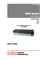
As shown in Figure 2.1, the SRM front panel includes the following components:
RESET: Can be used to restart the SRM operating system as described in
Section 2.3.
DEFAULT: Can be used to initialize the SRM to default parameters as described in
Section 2.3.
ON: Lights when AC Power is applied.
à RDY: (Ready) Flashes when the unit is ready to receive commands.
ModemStatusIndicators: Four LEDs which function as follows:
• DCD: (Data Carrier Detect) Lights when the DCD signal is present.
• RXD: (Recieve Data) Lights when the RXD signal is present.
• DTR: (Data Terminal Ready) Lights when the DTR signal is present.
• TXD: (Transmit Data) Lights when the TXD signal is present.
SetUpPortActivityLED: Lights when the SetUp Port (Console Port) is active.
ModemPortActivityLED: Lights when the Modem Port is active.
Dialtone: Lights when a dialtone is detected.
STATUS
MODEM
STATUS
PORT
ACTIVITY STATUS
ON RDY DCD SETUP MODEM DIALTONERXD DTR TXD
DEFRST www.wti.com
SRM
Secure Rack Modem
12 3 4 5 6 7 8
Figure 2.1: Front Panel

2-2
Unit Description
2.2. Back Panel
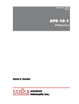
As shown in Figure 2.2, the SRM Back Panel includes the following components:
PowerInlet: An IEC-320-C14 inlet, for connection to your 100 to 240 VAC power
supply.
Note: 48 VDC powered models include a terminal block assembly (see
Figure 4.1) in place of the power inlet. For more information, please refer to
Section 4.1.3.
SwitchedContact: A dry contact that can be connected to an external alarm unit.
When an external alarm unit is connected to the Switched Contact, the alarm unit
will be activated when the No Dialtone Alarm is triggered. For more information on
the No Dialtone Alarm, please refer to Section 7.5. The switched contact includes
three pins: A Normally Closed (NC) pin, a Common (COM) pin and a Normally
Open (NO) pin. The switched contact is rated for 2 Amps maximum.
SetUpPorts: A USB Mini Port and an RJ45 Serial Port that can be used to connect
a local device to the SRM unit as described in Section 4.2. For a description of the
Setup Port interface, please refer to Appendix B.
à ModemPorts: An RJ45 RS232 serial port (DCE configuration) and a DB25 serial
port that can be used for connection to a PC or tablet.
NetworkPort: An RJ45 Ethernet port for connection to your 10/100Base-T,
TCP/IP network. Note that the SRM features a default, IPv4 format IP address
(192.168.168.168). This allows you to connect to the unit without first assigning an
IP address. Note that the Network Port also includes two, small LED indicators for
Link and Data Activity. For more information on Network Port configuration, please
refer to Section 6.6.
PhoneLinePort: The phone line port is used for connection to your external
phone line.
Ethernet RJ11
PHONE
ACT LINK
100 - 120V ~ 50/60 Hz 0.2A
SETUP PORT MODEM PORT
USB MINI
NC NOCOM
NC NOCOM
SERIAL RJ45 DB25
12 3 4 5 6
Figure 2.2: Back Panel

2-3
Unit Description
2.3. Front Panel Button Functions
The front panel buttons can be used to perform several functions described below:
Notes:
• FrontPanelbuttonfunctionscanalsobedisabledviatheSystemParameters
menu, as described in Section 6.2.
• WhentheSRMisresettofactorydefaults,alluser-definedconfiguration
parameters will be cleared and the default “super” user account will also be
restored.
• Duringtherebootprocedure,allportactivityLEDswillflashonce.
1. RebootOperatingSystem-KeepUser-DefinedParameters:
a) Press and hold the CLEAR (or RESET) button for five seconds, and then
release.
b) The SRM operating system will reboot; all user-defined parameters will be
retained.
2. RebootOperatingSystem-ResetAllParameterstoFactoryDefaults:
a) Simultaneously press both the SET (or DEFAULT) button and the CLEAR (or
RESET) button, hold them for five seconds, and then release.
b) The SRM operating system will reboot; all user-defined parameters will be reset
to factory default settings.
Note:TheRDYIndicatorwillcontinuetoblinkforabout45secondswhile
parametersarebeingerasedandkeysarerebuilt.TheRDYIndicatorwillthen
stop blinking during the reboot.

3-1
3. Getting Started
This section describes a simplified installation procedure for the SRM hardware, which
will allow you to communicate with the unit in order to demonstrate basic features and
check for proper operation. Note that this Quick Start procedure does not provide a
detailed description of unit configuration, or discuss advanced operating features in
detail. For more information, please refer to the remainder of this User’s Guide.
3.1. Apply Power to the SRM
Refer to the safety precautions listed at the beginning of this User's Guide, and then
connect the unit to an appropriate power source. Connect the power supply cable to
the unit’s power inlet, snap the Cable Keeper into place, and then connect the cable
to an appropriate power supply. Please refer to the power rating label on the unit
concerning power requirements and maximum load.
When power is applied to the SRM, the ON LED on the instrument front panel should
light, and the RDY LED should begin to flash within 90 seconds. This indicates that the
unit is ready to receive commands.
3.2. Connect Your PC to the SRM
The SRM can either be controlled via local PC Serial Port, USB Mini Port, modem,
or TCP/IP network. In order to connect ports or select parameters, commands are
issued to the SRM via either the Network Port, Modem or Setup Port. Note that it is not
necessary to connect to both the Network and Setup Ports.
• NetworkPort: Connect your network interface to the SRM's Network port.
• SetUpPort: Connect your PC COM Port to either the RJ45 Serial SetUp Port or
USB Mini Port.
► RJ45SetUpPort: When connecting to the RJ45 SetUp Port, use the supplied
DX9F-DTE-RJ adapter and RJ45 Ethernet cable to connect your PC COM port to
the SRM's SetUp Port (Serial Port 1.) For a description of the RJ45 SetUp Port,
please refer to Figure B.1.
► USBMiniSetUpPort: When connecting to the USB Mini Port, use a standard
USB Mini Port cable.
• ModemPort: The Modem Port includes both a DB25 Connector and an RJ45
connector. Note that both ports cannot be used at the same time. In the default
state the Modem is connected to the Modem Port.
► DB25ModemPort: When connecting a PC or other device to the DB25 Modem
Port use a standard Modem Cable. For pinout, see Figure B.2.
► RJ45ModemPort: When connecting a PC or other device to the RJ45
connector, use a standard Ethernet patch cable. For pinout, see Figure B.3.
• PhoneLine:Connect your phone line to the SRM’s RJ11 Phone Line Port. For a
description of the RJ11 Phone Line Port pinout, please refer to Figure B.4.

3-2
Getting Started
3.3. Communicating with the SRM
The SRM command mode can be used to configure the unit's internal modem,
selected communication parameters, define user accounts and to perform other unit
management related functions. When properly installed and configured, the SRM will
allow command mode access via Telnet, Web Browser, SSH client, modem, or local
PC. However, in order to ensure security, both Telnet and Web Browser access are
disabled in the default state. To enable Telnet and/or Web Browser access, please refer
to Section 6.6.2.
Notes:
• DefaultSRMserialportparametersaresetasfollows:9600bps,RTS/
CTSHandshaking,8DataBits,OneStopBit,NoParity.Althoughthese
parameters can be easily redefined, for this Quick Start procedure, it is
recommended to configure your communications program to accept the
default parameters.
• TheSRMfeaturesadefaultIPAddress(192.168.168.168)andadefault
SubnetMask(255.255.255.0.)Thisallowsnetworkaccesstocommand
mode,providingthatyouarecontactingtheSRMfromanodeonthesame
subnet.WhenattemptingtoaccesstheSRMfromanodethatisnotonthe
same subnet, please refer to Section 6.6 for further configuration instructions.
• WhenconnectingonlyasinglenetworkcabletoaSRMunitthatincludes
twoEthernetports,makecertaintoconnecttoPortETH0(theupperEthernet
Port.)
1. AccessCommandMode:The SRM includes two separate user interfaces; the Text
Interface and the Web Browser Interface. The Text Interface is available via Local
PC, SSH Client, or Telnet and can be used to both configure the SRM and create
connections between ports. The Web Browser interface is only available via
TCP/IP network, and can be used to configure the unit, but cannot create
connections between ports.
a) ViaSetUpPort: Start your communications program, then select the
appropriate COM port and press [Enter]. Note that when viewed by a PC
running Windows XP or later, the Serial COM Port menu will list the USB Mini
Port as, "USB to Serial."
b) ViaSSHClient: Start your SSH client, enter the default IP address
(192.168.168.168) for the SRM and invoke the connect command.
c) ViaWebBrowser: Make certain that Web Browser access is enabled as
described in Section 6.6.2. Start your JavaScript enabled Web Browser, enter
the default IPv4 format SRM IP address (192.169.168.168) in the Web Browser
address bar, and then press [Enter].
d) ViaTelnet: Make certain that Telnet access is enabled as described in
Section 6.6.2. Start your Telnet client, and enter the SRM's default IPv4 format
IP address (192.168.168.168).

3-3
Getting Started
2. Username/PasswordPrompt: A message will be displayed, which prompts you
to enter your username (Login) and password.. The default username is "super"
(all lower case, no quotes), and the default password is also "super". If a valid
username and password are entered, the SRM will display either the Main Menu
(Web Browser Interface) or the Port Status Screen (SSH, Telnet, or Modem.)
Notes:
• ThedefaultUsernameis"super".
• ThedefaultPasswordis"super"
• IfaLoginBannerhasbeendefinedasdescribedinSection6.2,thena
banner page will appear before the command interface is displayed. The
LoginBannercanbeusedtodisplaylegalwarningsorotherinformation.
3. ReviewHelpMenu: If you are communicating with the SRM via the text interface
(SSH, Telnet or Modem), type /H and press [Enter] to display the Help Menu,
which lists all available SRM commands. Note that the Help Menu is not available
via the Web Browser Interface.

3-4
Getting Started
3.4. Basic Modem Commands
This section describes basic Modem AT commands that can be used to demonstrate
basic modem capabilities. For a complete list of available modem commands, please
refer to the AT Command Reference Guide, which can be found in WTI's online User's
Guide Archive at: http://www.wti.com/t-product-manuals.aspx
AT Attention command. Must be included as a prefix for all commands unless
otherwise noted.
+++ Switches Modem from data mode to command mode. This command is
not proceeded by the AT command. The +++ command can be used in
conjeunction with the Hn command to disconnect a session. To disconnect,
enter the +++ comand followed by a one second delay, type ATH and then press
[Enter]
(e.g., +++ ATH [Enter])
A Tells the modem to attempt to answer an incoming call. (e.g., ATA)
Dn Causes the modem to dial the number n. Offers the following command options:
T (Tone Dialing,) P (Pulse dialing,) - (Pause 2 seconds,) @ (Wait for 5 seconds of
silence,) L (Call last number dialed.) (e.g., ATD 5551212)
En Toggles command echo On/Off. Allows commands to either be displayed or
hidden (0 = Off, 1 = On.) (e.g., ATE1)
Hn When data mode is active, this command instructs modem to hang up or pick up
(0 = hang up, 1 = pick up.) (e.g., ATH1)
Qn Displays/hides result codes. (0 = Display result codes, 1 = Hide Result codes.)
(e.g., ATQ1)
S0=n Number of rings to answer. (e.g., ATS0=1 will cause the modem to answer on
the first ring.)
Z Soft Reset. Restores basic defaults. (e.g., ATZ)
&Fn Resets modem to factory settings. (0 = Fetch default configuration, 1 = Recall
factory default configuration, 2 = Recall Sierra factory default for auto.)
(e.g., AT&F1)

3-5
Getting Started
3.5. The WMU Enterprise Management Solution
The WMU Enterprise Management Solution provides a centralized interface that can be
used to configure, manage and control multiple WTI out-of-band management devices
spread throughout a large corporate network infrastructure. When installed at your
network operation center or support facility, the WMU eliminates the need to individually
access WTI units in order to perform firmware updates, edit user accounts and perform
other management and control functions.
The WMU software and user's guide can be downloaded at:
ftp://wtiftp.wti.com/pub/TechSupport/WMU/WtiManagementUtilityInstall.exe
This completes the Quick Start procedure for the SRM. Prior to placing the unit into
operation, it is recommended to refer to the remainder of this user’s guide for important
information regarding advanced configuration capabilities and more detailed operation
instructions. If you have further questions regarding the SRM unit, please contact WTI
Customer Support as described in Appendix C.

4-1
4. Hardware Installation
4.1. Connecting the Power Supply Cables
4.1.1. Connect the SRM to Your Power Supply
Refer to the cautions listed below and at the beginning of this User's Guide, and then
connect the SRM unit to an appropriate power supply.
CAUTIONS:
• Beforeattemptingtoinstallthisunit,pleasereviewthewarningsand
cautions listed at the front of the user’s guide.
• Thisdeviceshouldonlybeoperatedwiththetypeofpowersource
indicated on the instrument nameplate. If you are not sure of the type of
powerserviceavailable,pleasecontactyourlocalpowercompany.
• Reliableearthing(grounding)ofthisunitmustbemaintained.Particular
attentionshouldbegiventosupplyconnectionswhenconnectingto
powerstrips,ratherthandirectlytothebranchcircuit.
4.1.2. Installing the Power Supply Cable Keeper
The SRM includes a cable keeper, which is designed to prevent the AC power supply
cable from being accidentally disconnected from the unit.
When attaching power supply cable(s) to the unit, first swing the cable keeper out of
the way, then plug the power cable securely into the power input. When the cable is in
place, snap the cable keeper over the plug to secure the cable to the unit.
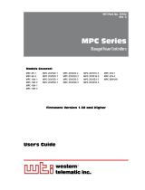
4.1.3. DC Powered Units
When connecting a DC Powered SRM unit to your DC Power source, note that the DC
terminal block is designed for connection to two separate power sources. First remove
the protective cover from the terminal block, attach the wires from the -48 VDC power
sources to the screw terminals, connect the ground line to the labeled ground screw,
tighten the screw terminals, making certain that the wires are securely fastened, and
then replace the protective cover.
-48V
-48V -48V00
0.1A
BUS A BUS B
Ground Screw
Figure4.1:TerminalBlockAssembly(DCUnitsOnly)

4-2
Hardware Installation
4.2. Cable Connection
4.2.1. Connecting the Network Cable
The Network Port is an RJ45 Ethernet jack, for connection to a TCP/IP network.
Connect your 100Base-T cable to the Network Port. Note that the SRM includes a
default IPv4 protocol IP address (192.168.168.168) and a default IPv4 protocol subnet
mask (255.255.255.0.) When installing the SRM in a working network environment, it is
recommended to define network parameters as described in Section 6.6.
4.2.2. The Modem Port
The Modem Port includes both a DB25 Connector and an RJ45 connector. Note that
both ports cannot be used at the same time. In the default state the internal Modem is
connected to the Modem Port. For a description of the Modem Port pinout, please refer
to Appendix B.
• DB25ModemPort: When connecting a PC or other device to the DB25 Modem
Port use a standard Modem Cable. For pinout, see Figure B.2.
• RJ45ModemPort: When connecting a PC or other device to the RJ45 connector,
use a standard Ethernet patch cable. For pinout, see Figure B.3.
4.2.3. The SetUp Ports
In order to select configuration parameters and review unit status, commands are issued
to the SRM via either the Network Port or Setup Port. Note that it is not necessary to
connect to both the Network and Setup Ports. Connect your PC COM Port to either the
RJ45 format Serial SetUp Port or USB Mini format SetUp Port. For a description of the
RJ45 SetUp Port pinout, please refer to Appendix B.
• RJ45SetUpPort: When connecting to the RJ45 SetUp Port, use the supplied
DX9F-DTE-RJ adapter and RJ45 Ethernet cable to connect your PC COM port to
the SRM's SetUp Port (Serial Port 1.)
• USBMiniSetUpPort: When connecting to the USB Mini Port, use a standard USB
Mini Port cable.
4.2.4. The Phone Line Port
Connect your RJ11 phone line to the RJ11 Phone line connector. For information on
Modem configuration, please refer to Section 6.5.2.3. For a description of the Phone
Line Port pinout, please refer to Appendix B.
This completes the SRM installation instructions. Please proceed to the next Section for
instructions regarding basic unit configuration.
/