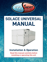
Calorex AA 300-500 Installation guide

Category
Above ground pool accessories
Type
Installation guide

This manual is also suitable for

AA300AVH/AA500AVH
Owner installation manual (SD611250 issue 7)
2 SD611250 ISSUE 7
AA300AVH/AA500AVH OWNER INSTALLATION MANUAL
Contents
HEATH AND SAFETY WARNING ..............................................4
1.0 HOW THE CALOREX ‘AA300/AA500’ WORKS ..............5
FEATURES....................................................................................6
1.1 OPERATION ..........................................................................8
1.2. HUMIDITY & AIR TEMPERATURE AND CONTROLS ...... 9
1.3 TIME CLOCK SETTINGS ................................................... 10
2.0 INSTALLATION .................................................................. 11
SITING, MACHINE LOCATION ................................................ 12
2.1 PLUMBING ......................................................................... 14
2.2 WATER CONNECTIONS .................................................... 15
2.3 ELECTRICAL INSTALLATION ........................................... 16
2.3.1 MAINS SUPPLY TERMINAL BLOCK LAYOUT ............ 17
2.3.2 NOTES ON TERMINAL BLOCK CONNECTIONS ......... 18
2.4 COMMISSIONING CHECKLIST ........................................ 19
2.5 CIRCUIT DIAGRAMS ......................................................... 20
2.6 REGULAR PLANNED MAINTENANCE ........................... 26
3.0 CONTROLS......................................................................... 27
4.0 DATA SHEET ...................................................................... 31
5.0 DIMENSION DRAWING .................................................... 32
6.0 WARRANTY CONDITIONS ............................................... 33
HEALTH AND SAFETY WARNING
As e dehumidifier embodies electrical and rotational equipment, ONLY competent persons
should carry out any work on is type of machine.
(SEE GUARANTEE)
3
SD611250 ISSUE 7
HEALTH AND SAFETY WARNING
This appliance is not intended for use by persons (including children) wi reduced physical,
sensory or mental capabilities, or lack of experience and knowledge, unless ey have been given
supervision or instruction concerning use of e appliance by a person responsible for eir safety.
Children should be supervised to ensure at ey do not play wi e appliance.
Disconnect from e mains supply and wait ree minutes before removing panels and
commencing work on is machine.
HEALTH AND SAFETY WARNING
4 SD611250 ISSUE 7
AA300AVH/AA500AVH OWNER INSTALLATION MANUAL
1.0 HOW THE CALOREX ‘AA300/AA500’ WORKS
The Calorex ‘AA300 and AA500’ are packaged refrigerant type dehumidifiers
at are specifically designed to provide humidity control and room heating
(optional) for a swimming pool hall.
The Calorex units are designed to be connected into an air distribution system
at will provide a uniform flow of air rough out e hall. An optional fresh air
entry point is available.
The Calorex ‘AA300/AA500’ works by physically removing excess moisture
from e pool hall air. This is achieved by recirculating air from e pool hall
rough e unit and removing moisture from e air by use of e machines
internal refrigeration circuit.
As a by product of is process e Calorex ‘AA300/AA500’ will convert e
energy it has absorbed into sensible heat. This heat is added back into e
return air stream and consequently provides supplementary hall heating.
For every 1kw of power consumed e Calorex ‘AA300/AA500‘ will return
approximately 2.5kW of heat. This process is controlled by a humidistat at
measures e pool hall humidity and controls e machine to a set point at
can be adjusted to suit e clients need.
As an option e Calorex ‘AA300/AA500’ can be supplied wi a low pressure
hot water (LPHW) air heater. The LPHW should be fed wi hot water at 80ºC#
and will provide space heating for e pool hall. The LPHW is integrally fitted
into e Calorex ‘AA300/AA500’ and is supplied wi an adjustable ermostat,
ree way control valve and a switch relay to control a boiler or pump. The
boiler and pump are not supplied wi is option.
# Note.
Consult Danerm Ltd. for heat exchangers at are suitable for lower flow
temperatures.
Humid Air Dry,
Warm Air
20ºC
80%
28ºC
40%
Evaporator
Expansion
Condensate
to waste
Principles of operation - air to air dehumidifier
The process of dehumidification involves moisture laden air being drawn rough a refrigerated
coil (evaporator). At is point e air is rapidly cooled below its dew point, condensing e water
vapour and recovering its latent heat energy for reuse. The cooled air is en passed across a
condenser where it is reheated and returned to e room as warm, dry air.
How a Calorex Dehumidifier Works
Condenser Compressor
3
SD611250 ISSUE 7
THE CALOREX AA300 AND AA500.
FEATURES
1.Remote control panel
The Calorex ‘AA300/AA500’ is supplied as standard wi a remote control
panel at can be mounted up to 20m away from e unit. (The cable supplied
wi e AA300/AA500 is 1.8m).The control panel features 12V circuits and
interconnecting cable is easily connected to e unit by ‘D’ type fittings.
The control panel will indicate pool hall humidity rough an adjustable set point
digital humidistat, power on, fault, machine ‘dehumidifying’ and defrost status.
An on/off switch is also provided.
When e unit is supplied wi an optional LPHW e panel will also indicate
pool hall air temperature rough an adjustable set point ermostat. A time
clock will allow ‘set back air temperature’ for unoccupied periods. An indicator
light will show when e unit is heating.
The power to each model in e range is fed via din rail mounted terminal
blocks located in e electric box of e unit.
CONTROL PANEL STANDARD UNIT
CONTROL PANEL WITH AIR LPHW FITTED
Humidity display
and lamp
Mains On/Off
switch
Mains lamp
Fault lamp
Defrost lamp
Humidity display
and lamp
Mains On/Off
switch
Mains lamp
Fault lamp
Defrost lamp
Air temperature
display and lamp
Time Clock
4 SD611250 ISSUE 7
AA300AVH/AA500AVH OWNER INSTALLATION MANUAL
Humidity display
and lamp
Mains On/Off
switch
Mains lamp
Fault lamp
Defrost lamp
Air temperature
display and lamp
Time Clock
Water temperature
display and lamp
Economy
switch
CONTROL PANEL WITH AIR AND WATER LPHW FITTED
2. Constant flow centrifugal fan.
When e AA300/AA500 is delivered e fan is set to run at two speeds:
medium speed when e machine senses a demand for dehumidification
(and air heating) and low speed for when ere are no demands.
If little or no ducting is fitted and e air flow is too high, e top speed of e
fan can be changed from high to medium. See instructions on page 10 and
circuit diagram in section 2.5 for instructions on how to do is.
When fitting e remote sensor box it is possible to switch off e low
speed fan MCB us making e fan run only when ere are demand for
dehumidification and/or air heating. See page 25.
3. Optional flexible duct fittings.
4. Rotary compressor
5. A non CFC refrigeration circuit.
5
SD611250 ISSUE 7
1.1 OPERATION
The AA300/AA500 is connected to e control panel and en to e isolated
mains supply as described in section 2.3. The isolator is en energised. The
MAINS light on e side of e heat pump will illuminate indicating mains ON.
If e AA300/AA%00 is fitted wi an LPHW e time clock will start to run.
The time clock has a battery reserve fitted which when charged will run for
100 hours so at isolating e machine for short periods will not affect e time
clock settings.
The AA300/AA500 unit is switched on to normal operation by an ON (I)/OFF
(O) switch on e console.
When switched on e red indicator light will illuminate and digital controller(s)
will light up.
Providing at e controls are set to e correct parameters; nominally 60%
RH, (28ºC air temperature), e machine will operate automatically.
For AA300/AA500s wi LPHW fitted, e ‘unoccupied’ temperature is set on
e digital air controller and will be switched in/out by e time set on e time
clock.
As e unit operates, e indicator lights will show e state of e control
conditions, ie dehumidification, heat to air.
See section 3.0 for control panel symbols.
PARAMETER CONTROLLERS
Each parameter, Relative Humidity (and Air Temperature) is sensed wiin e
machine and e signal is taken to e relevant digital controller.
The RH controller has two switching channels, OUT1 (e Set Point) which is
set from e front panel, and OUT2 which is factory preset.
When fitted, e Air Temperature controller has ree switching channels, one
of which is for setting e OCCUPIED/ UNOCCUPIED air temperature. (See
section 1.2)
When fitted, e Water temperature controller has two switching channels,
OUT1 (e Set Point) which is set from e front panel, and OUT2 which is
factory preset.
Each channel has a switching differential which is also factory pre-set. None of
e factory settings should be tampered wi.
When e re-settable channel is adjusted all oer settings and differentials
automatically follow at e correct relationship.
Nominal set point values & diffs
RH% = 60% diff 3%
Air temperature = 28ºC diff 0.5 ºC
Water temperature = .26ºC diff 0.2 ºC
Please note: on AA machines wi LPHW, in occupied mode dehumidification
stops once e air temperature is 2.5ºC above set point.
6 SD611250 ISSUE 7
AA300AVH/AA500AVH OWNER INSTALLATION MANUAL
1.2. HUMIDITY & AIR TEMPERATURE AND CONTROLS
HUMIDITY DIGITAL CONTROLLERS
To Program e Set Point. Press down P, SP1 and Set Point value will be
displayed alternately.
Press e or key to change e value of SP1. Once e desired value is
displayed press P to memorise e value. The display will revert to e present
reading.
NOTE: If anying else shows on e display leave alone for 1 minute until e
display returns to normal.
AIR TEMPERATURE DIGITAL CONTROLLER AND AA
MACHINES WITH AIR HEATING
The digital controller for controlling air temperature can be changed as follows:
To program e set point, press P button once and release it. SP1 (set point)
and set point value e.g. 28 will be displayed alternately. Press P again AL1
(-4.5) will show. This is e difference between e set point and AL1 plus
a constant 0.5 e.g. 28 - 4.5 + 0.5 = 24ºC (unoccupied) SP1 and AL1 can be
changed in e same way as described for humidity.
NOTE: AL1 can only be set -1 to -10 below SP1 value.
WATER TEMPERATURE CONTROLLER
To Program e Set Point. Press down P, SP1 and Set Point value
will be displayed alternately.
Press e or key to change e value of SP1. Once e
desired value is displayed press P to memorise e value. The
display will revert to e present reading.
NOTE: If e readings on e digital controllers are not e same as e actual
pool hall conditions, an offset into e digital controller can be set. However,
before is is done an inspection of e installation should be made to ensure air
conditions into e unit are e same as ose in e pool hall. Air leakage into
e units return air from oer spaces should be sealed before adjustments are
made. See technical manual.
NOT USED
INCREASE SET POINT
DECREASE SET POINT
ACCESS SET POINT
7
SD611250 ISSUE 7
1.3 TIME CLOCK SETTINGS
TIME CLOCK (Machines wi LPHW only)
The time clock is a quartz 24 hour clock wi 100 hours battery reserve used
to control e automatic operation on e AA300/500 units per 24 hour time
cycles.
The time clock setting determines e OCCUPIED/UNOCCUPIED periods and is
set to match e operators requirements regarding opening and closing times
for e pool and possible times where e pool is covered.
The two settings are OCCUPIED or day time, and UNOCCUPIED or night time
(covered).
The most obvious action of is change is to lower e pool hall air temperature
to a determined level to conserve air heating energy. This lowering of
temperature is allowable because of e quiescent, and ideally covered,
condition of e pool.
Pool water occupied
(no pool cover)
Pool water unoccupied
(pool covered)
SETTING ACTUAL TIME
Turn e large clock hand clockwise until e correct time of day is set, ensuring
at e correct half of e day is chosen (24 hour clock).
SETTING FOR AUTOMATIC OCCUPIED/UNOCCUPIED
OPERATION WITH TIME CLOCK
To set for automatic time clock control of occupied/unoccupied, slide e lever
to ‘A’. Each yellow segment represents a 15 minute time period. Extend
outward e segments for a period of time when e pool is occupied (i.e. used
or uncovered) per day.
SETTING FOR AUTOMATIC OCCUPIED/UNOCCUPIED
OPERATION WITH REMOTE INTERFACE
To set for remote control of occupied/unoccupied, slide lever to ‘O’. See section
2.3.2, Note 1 for more information on remote interface.
SETTING FOR MANUAL OCCUPIED/UNOCCUPIED OPERATION
To set for manual occupied period (or override automatic unoccupied period)
slide e lever to ‘I’ for ‘occupied’.
=
=
O
SEGMENTS
AUTOMATIC AND
MANUAL SETTING
LEVER
8 SD611250 ISSUE 7
AA300AVH/AA500AVH OWNER INSTALLATION MANUAL
On delivery e console for e AA300/AA500 will be inside e
machine. To retrieve e console unfasten e removable panel
on e heat pump. The console should be in e position shown,
protected by bubblewrap.
Note: e removable panel is on e opposite face of e heat
pump to e water connections.
When a machine is supplied wi Air and Water LPHW e console
will be in a box on top of e machine.
2.0 INSTALLATION
UNPACKING
CONTROL CONSOLE
D
REMOVABLE
PANEL
CONSOLE*
DUCT
CONTROL CONSOLE
WITH AIR LPHW
FITTED
ºC
%
=?
=?
= AUTO
CONTROL CONSOLE
CONNECTION POINT
CONTROL CONSOLE
WITH AIR AND WATER
LPHW FITTED
*EXCEPT WHEN A
MACHINE WITH AIR AND
WATER LPHW IS
ORDERED
ºC
ºC
\
\
%
= AUTO
CONSOLE IN
AIR AND WATER
LPHW MACHINES
9
SD611250 ISSUE 7
SITING, MACHINE LOCATION
If e optional flexible ducting flange is not used, due consideration to resonant
noise rough e duct work must be made.
Ensure duct work pressure drop does not exceed resistance given in data sheet.
If unit is located in a plant room at pool hall air temperatures, any ambient air ducting must be heavily insulated.
Recommend fresh air/exhaust spring return dampers to be fitted to ductwork for sub zero ambient
applications in case of power failure.
800
AIR FILTER ACCESS
800
SERVICE ACCESS
TO ELECTRIC BOX
BOILER WATER
CONNECTIONS
(AIR AND WATER
LPHW VERSIONS)
CONSOLE
POSITION
AIR ON AIR OFF
CONTROL PANEL
CONNECTION POINT
RED LAMP 12V
REMOTE CONTROL
PANEL LIVE
INDICATION
FILTER ACCESS PANEL
SERVICE
PANEL
ALTERNATIVE
CONSOLE
POSITION
CONDENSATE
DRAIN CONNECTION
POOL WATER
CONNECTIONS
(WATER LPHW
VERSION)
10 SD611250 ISSUE 7
AA300AVH/AA500AVH OWNER INSTALLATION MANUAL
INSTALLATION WITH OPTIONAL FEATURES
Ensure duct work pressure drop does not exceed resistance given in data
sheet.
If unit is located in a plant room at pool hall air temperatures, any ambient air
ducting must be heavily insulated.
Recommend fresh air/spring return dampers to be fitted to Fresh air ductwork
for sub zero ambient applications in case of power failure.
Ensure duct work pressure drop does not exceed resistance given in data sheet.
If e static resistance drops below e figure stated in e data sheet and a greater air flow is required, it is possible to
change e speed of e fan from non 'F' to 'F'.
Wi e machine isolated move e blue wire connected to terminal 17 on e fan motor to terminal 18 on e fan
motor. (See circuit diagram section 2.5)
If unit is located in a plant room at pool hall air temperatures, any ambient air ducting must be heavily insulated.
Recommend fresh air/exhaust spring return dampers to be fitted to ductwork for sub zero ambient
applications in case of power failure.
OPTIONAL FLEXIBLE
DUCTING FLANGE
FILTER ACCESS PANEL
OPTIONAL FLEXIBLE
DUCTING FLANGE
SERVICE
PANEL
CONSOLE
POSITION
ALTERNATIVE
CONSOLE
POSITION
SERVICE
ACCESS TO ELECTRIC BOX
800
AIR ON
BLANKING PLATE
FOR OPTIONAL
FRESH AIR GRILLE
4 HOLES DIA 6 ON
125mm DIA.
CONTROL PANEL
CONNECTION POINT
RED LAMP 12V
REMOTE CONTROL
PANEL ON
INDICATION
11
SD611250 ISSUE 7
2.1 PLUMBING
CONDENSATE DRAIN
The condensate driptray in e ‘AA300/AA500’ unit collects e water
removed by e dehumidification process.
It is erefore necessary to ensure at e’AA300/AA500’ unit is placed on a
level plin so at e condensate can run away and not overflow e edges of
e driptray inside e machine.
The ‘AA300VHF’ has a 3/4” BSPM readed condensate drain connection.
The drain pipe should run away wi adequate fall to waste ie 1/2” per foot
minimum and must incorporate a ‘U’ trap & tun dish.
BOILER PLUMBING
The boiler connections on e machine are 3/4”BSPM. for connecting e boiler
water flow and return.
Suitable breakable couplings, isolation, and drain down valves should be
installed in e boiler water flow and return pipes local to e ‘AA300/AA500’
unit.
Refer to e boiler manufacturers instructions before designing e pipework
system.
POOL WATER CONNECTIONS
The pool water connections in e machine are 1” BSPM uPVC.
Suitable breakable couplings, isolation, and drain down valves should be
installed in e pool water flow and return pipes local to e ‘AA300/AA500’
unit.
IMPORTANT GENERAL CONDITIONS
1) Do not route water pipes across service access panels or air inlet/outlets.
2) The water circuits to and from e ‘AA300/AA500’ unit should be capable
of maintaining e specified water flow limits required by e machine. See Data
sheet section 4.0.
3) All pipework must be adequately supported wi allowance for expansion
and contraction especially wi regard to e plastic pipework.
4) It is recommended at when installing water systems e last connections
to be made should be adjacent to e ‘AA300/AA500’ unit to avoid undue
stresses on e unit connections.
12 SD611250 ISSUE 7
AA300AVH/AA500AVH OWNER INSTALLATION MANUAL
2.2 WATER CONNECTIONS
(ALSO SEE SECTION 2.1)
CUSTOMERS "TUN DISH"
AA300 DRAIN
COPPER STUB
DRAIN TO WASTE
U TRAP
AA300 UNIT
BOILER WATER SCHEMATIC
BOILER
PUMP RADIATORS
(IF FITTED)
FLOW
BALANCE
VALVE
INTERNAL 3 WAY MOTORISED VALVE
(DIVERTING) CONTROLLED BY VARIHEAT .
FLOW METER LPHW
CONNECTIONS
AW300/AA500AVH
CABINET
(FACTORY SET)
CONDENSATE DRAIN 3/4" BSPM (BRASS)
POOL WATER IN/ OUT 1" BSPM (u PVC)
BOI L ER WA TER I N / O U T 3/ 4 " BSPM ( BRASS)
WATER
OUT
WATER
IN
WATER
IN
WATER
OUT
CONDENSATE DRAIN PLUMBING
WATER CONNECTIONS
13
SD611250 ISSUE 7
ELECTRICAL SAFETY
It is important to ensure at all aspects of e installation comply wi e latest
I.E.E. Regulations.
It is also important to ensure at any remote devices which terminate
wiin e pool hall are of e type and voltage as specified in e latest I.E.E.
Regulations.
The machine should be installed in accordance wi EMC2004/108/EC.
PROTECTED SUPPLY
Whilst not mandatory, Danerm Ltd. recommends at an R.C.C.B. is always
fitted or at e supply is to local electricity auority recommendations, and
at all ducting is bonded in accordance wi ese regulations.
The supply to e machine should incorporate fuses or motor rated circuit
breakers (type GU) to specified rating (see data sheet) H.R.C. fuses are
recommended. An all pole swtched isolator must be fitted wiin clear view
of e machine and not more an 2 metres away. The isolator must have a
minimum of 3mm air gap when in e off position.
INCONSISTENT ELECTRICAL SUPPLY.
The following limits of operation must not be exceeded if Calorex machines are
to be guaranteed eier in performance or warranty terms :
Min Max
Voltage, single phase 207V 253V
Frequency 47.5Hz 52.5Hz
N.B The voltage must be measured at e heat pump mains terminals wi all
e fans/compressors
running at e rated condition.
CORRECT CABLE SIZING
The cable supplying electricity to a machine wi a given load must increase in
cross sectional area (CSA) as e leng increases in order at e voltage drop
wiin e cable does not exceed recommended limits.
Cable sizing should be calculated by an approved electrician wi due
consideration to I.E.E. and local codes of practice.
MAINS ENTRY
POINT
ELECTRIC BOX LIVE
INDICATOR LAMP
CONTROL CONSOLE
CONNECTION POINT
REMOVE LID TO GAIN
ACCESS TO ELECTRIC BOX
ELECTRIC BOX
REMOTE
OVERRIDE
SWITCH
REMOTE
ON/OFF
(12V)
N L
BOILER
DEMAND
REMOTE
POWER
INDICATER
(12V)
F1 2.5A
F2 1.0A
COMP
FAN H
FAN L
CONT
A1
A2
1 2
34
56
21 22
COMP
CONT
RE1 R1 R2 R3 R4
4 5 6 7 8 9 1011 12
13141516171819202122232425262728293031
2.3 ELECTRICAL INSTALLATION
14 SD611250 ISSUE 7
AA300AVH/AA500AVH OWNER INSTALLATION MANUAL
2.3.1 MAINS SUPPLY TERMINAL BLOCK LAYOUT
TERMINAL
BLOCK UNDER
FLANGE IN
ELECTRIC BOX AIR
PROBE
HUMIDITY
SENSOR
P5 P6 P7
P3 P4
34 5
12
TERMINALS IN
REMOTE
SENSOR BOX
OPTIONAL REMOTE SENSOR BOX
SWITCHED FUSED ISOLATOR TO BE
WITHIN SIGHT OF FRONT OF UNIT &
NOT MORE THAN 2M AWAY
N
SWITCHED FUSE
ISOLATOR SEE
DATA SHEET FOR
RATINGS
L
NOTE 'a'
LINK THESE TERMINALS WHEN REMOTE NOT REQUIRED
REMOVAL OF LINK WILL STOP FAN, COMPRESSOR &
DIGITAL CONTROLLERS .
1 2 3 4 5
NO LINK WIRES
NECESSARY IF TERM'S 6
TO 9 NOT IN USE
E LN
IF THIS FACILITY IS USED TIME CLOCK
(IF FITTED) MUST BE SET TO UNOCCUPIED
REMOTE OCC/UNOCCUPIED
SEE NOTE 1 SECTION 2.3.2
LOAD N
LUNIT WITH LPHW ONLY
BOILER DEMAND
SEE NOTE 3 SECTION 2.3.2
BOILER
DEMAND
12V REMOTE
CONTROL PANEL ON INDICATION
REMOTE
OCC/UNOCCUPIED
SOFT START
OPTIONS
23 24 ELECTRIC BOX
TERMINAL RAIL
6 7 8 9 10 11
REMOTE
ON/OFF
12V
15
SD611250 ISSUE 7
2.3.2 NOTES ON TERMINAL BLOCK CONNECTIONS
NOTE 1 - Remote occupied/unoccupied
These contacts (from terminals 10 & 11) are to enable e air temperature set
back facility to be remotely overridden.
There is a 12 V AC output from ese terminals and closing a remote switch
will enable e unit to regain e normal operating air temperature for when e
pool is in use.
This can be done via a voltage free pool cover switch or some oer form of
voltage free switch.
If is facility is used en e time clock (if fitted) on e control panel of e
unit should be set to e ‘unoccupied’ (O) position. (See note on time clock and
switch settings, section 1.3).
NOTE 2 - Boiler demand -AA+LPHW machines only
These are voltage free contacts (from terminals 6 & 7) rated at 3(1) Amp at
230 Volts.
If e low pressure hot water supply to e unit is to be governed by e
Calorex unit en ese contacts should be utilised to bring water to e unit via
e boiler, motorised valve, boiler pump etc. Remember e maximum inductive
load is one amp.
This is dependant on how e low pressure hot water supply to e unit has
been designed.
If e supply of low pressure hot water to e unit is not dependant on a signal
from e unit en ese contacts can be ignored.
CONTROL PANEL 25 WAY CABLE CONNECTION
Data signal between e console and e heat pump is via a 25 way cable
wi ‘D’ connection (plug & socket) bo ends. The cable provided wi e
heat pump is 1.8m in leng. An optional 10m cable is available, part number
SD434052. A recommended maximum distance between e console and e
heat pump is 20 metres, 2 cables being used.
16 SD611250 ISSUE 7
AA300AVH/AA500AVH OWNER INSTALLATION MANUAL
2.4 COMMISSIONING CHECKLIST
a) Is e building finished in accordance wi e original plans and specification.
b) Is e plenum chamber and all ductwork insulated, special attention should
be made to e insulation of e fresh air inlet ducting to prevent condensation
problems.
c) Are ere any significant draughts in e pool hall or plant room (plenum
installation) rough poorly fitting doors, windows, pipe ducts, etc. This will let in
unwanted ambient air raising e heating duty required.
d) Is fresh air ducting (if fitted) perfectly sealed from plant room.
NOTE: (c) and (d) above should be checked by measuring plant room and
pool hall air temperatures.If e plant room is acting as a plenum chamber bo
temperatures should correspond. If e plant room temperature is lower en
ambient air is leaking in, is leak should be located and rectified.
e) Are e fresh air inlets free from obstructions ie, undersize grilles, objects in
e pa of exhaust air deflecting it back to e fresh air inlet, etc.
f) Is ‘occupied / unoccupied’ set correctly, (set wi air ermostat) see section
3.2.2.
g) Is e time clock set correctly.
h) Has e fan speed been set to match e sensors fitted.
j) Any sign of abnormal operation such as water dripping should be reported
immediately to an installer or Danerm Ltd..
k) Has fan run amps been recorded against datasheet.
l) Has e unit been installed to allow service personnel access to all areas.
17
SD611250 ISSUE 7
ELECTRICAL CONTROL & POWER CIRCUIT ‘AA’ VERSION
2.5 CIRCUIT DIAGRAMS
CIRCUIT DIAGRAM
AA300/500AVH
D604450
COMPRESSOR
CONTACTOR
SEE BELOW
FAN RELAY
SEE BELOW
R01
R02
R03
R04
R05
16A 16A
AA300AVH/AA500AVH
MODEL FAN MCB COMP MCB
DEVICE VALUE
18 SD611250 ISSUE 7
AA300AVH/AA500AVH OWNER INSTALLATION MANUAL
  • Page 1 1
  • Page 2 2
  • Page 3 3
  • Page 4 4
  • Page 5 5
  • Page 6 6
  • Page 7 7
  • Page 8 8
  • Page 9 9
  • Page 10 10
  • Page 11 11
  • Page 12 12
  • Page 13 13
  • Page 14 14
  • Page 15 15
  • Page 16 16
  • Page 17 17
  • Page 18 18
  • Page 19 19
  • Page 20 20
  • Page 21 21
  • Page 22 22
  • Page 23 23
  • Page 24 24
  • Page 25 25
  • Page 26 26
  • Page 27 27
  • Page 28 28
  • Page 29 29
  • Page 30 30
  • Page 31 31
  • Page 32 32
  • Page 33 33
  • Page 34 34
  • Page 35 35
  • Page 36 36

Calorex AA 300-500 Installation guide

Category
Above ground pool accessories
Type
Installation guide
This manual is also suitable for

Ask a question and I''ll find the answer in the document

Finding information in a document is now easier with AI