Page is loading ...

Page 1
Calorex Heat Pumps Ltd. · The Causeway, Maldon, Essex CM9 4XD, UK · Tel: +44 (0)1621 857 171
Installation Manual
PPT8/12/16/22L/LY R
OWNER/INSTALLATION MANUAL
FOR
PPT8/12/16/22L/LY
(SD617650 Iss.X 08/12/09)
Health and Safety Warning:
As the heat pump includes electrical and rotational components it is required that only trained
and competent persons should remove panels giving internal access to the unit.

Calorex Heat Pumps Ltd. · The Causeway, Maldon, Essex CM9 4XD, UK · Tel: +44 (0)1621 857 171
Installation Manual
PPT8/12/16/22L/LY
Page 2
R
Congratulations!
You are now an owner of a Calorex Heat pump!

Page 3
Calorex Heat Pumps Ltd. · The Causeway, Maldon, Essex CM9 4XD, UK · Tel: +44 (0)1621 857 171
Installation Manual
PPT8/12/16/22L/LY R
Contents
1.0 Introduction and Function ........................................................................................... 4
1.1 Introduction ................................................................................................................ 4
1.2 Function .................................................................................................................... 5
2.0 Installation ................................................................................................................. 6
2.1 Siting ........................................................................................................................ 6
2.2 Air flow ...................................................................................................................... 7
3.0 Plumbing ....................................................................................................................8
3.1 Recommended Plumbing Schematic....................................................................... 10
3.2 Determining Water Flow .......................................................................................... 11
4.0 Electrolytic Corrosion in Swimming Pools................................................................ 12
4.1 Electrical (Machine Wiring and Supply). .................................................................. 13
4.2 Location of Mains Input and External Interlock Terminals .......................................... 14
5.0 Optional Features .................................................................................................... 15
5.1 Pool Pump Kit .......................................................................................................... 15
5.2 Remote Thermostat .................................................................................................. 17
6.0 Circuit Diagrams ..................................................................................................... 18
7.0 Regular planned maintenance ................................................................................. 25
8.0 Controls and indication lamps ................................................................................. 25
8.1 Digital Thermostat ................................................................................................... 27
9.0 Heat Pump Malfunction ............................................................................................ 27
10.0 Datasheets ........................................................................................................... 31
11.0 Installation Drawings .............................................................................................. 32
12.0 Winterisation Procedure ........................................................................................ 36
12.1 Start up Procedure After Winterisation ................................................................... 37
13.0 Warranty Conditions .............................................................................................. 38
14.0. Contacting Calorex ............................................................................................... 39

Calorex Heat Pumps Ltd. · The Causeway, Maldon, Essex CM9 4XD, UK · Tel: +44 (0)1621 857 171
Installation Manual
PPT8/12/16/22L/LY
Page 4
R
1.0 Introduction and Function
The Calorex ‘Propac’ range of air/water heat pumps are designed for swimming
pool heating and consists of 4 models. Heat pumps in this manual are
designed to heat pool water and spas within the range of 10°C to 40°C.
Standard units are suitable for outdoor pools operating in ambient temperatures
above 10ºC. Reverse cycle defrost models operate in ambient temperatures
down to -15ºC.The water heat exchanger is a full flow type, manufactured
from titanium tube, which is a highly corrosion resistant material. The heat
pumps are suitable for use in fresh water and salt water pools. PPT8/12 heat
pumps are fitted with rotary compressors and PP16/22 heat pumps are fitted
with scroll compressors. Both types of compressor are known for quiet running.
With these features the heat pump is designed to have a long, trouble free
life.
All units have integral safety devices to protect the heat pump from internal
and external faults. Indicator lamps indicate operating mode. An adjustable
digital thermostat controls water temperature. Also a 6 minute cycle time
delay is incorporated.
IMPORTANT NOTE
Calorex Heat Pumps Limited is an ISO9001:2000 certified company.
All Calorex heat pumps are CE approved
1.1 Introduction

Page 5
Calorex Heat Pumps Ltd. · The Causeway, Maldon, Essex CM9 4XD, UK · Tel: +44 (0)1621 857 171
Installation Manual
PPT8/12/16/22L/LY R
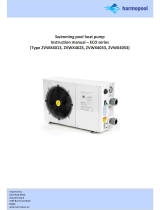
1.2 Function The Calorex Swimming pool heat pump provides thermodynamic heating by
means of a vapour compression cycle, (similar to that employed in a
conventional refrigerator), in addition to acting as an active solar collector.
Coefficient of Performance
The efficiency of a Heat Pump is usually called its ‘Coefficient of Performance’ - (C.O.P.)
which is simply a ratio of heat output to energy input, both being expressed in kW. Thus a
Heat Pump absorbing 1 kW of electricity, collecting 4 kW of energy from the air, and
delivering 5 kW of heat to the pool water is said to have a C.O.P. of 5:1.
This ratio will vary according to the temperature of the water and the ambient air.
2. THE COMPRESSOR where
it is compressed and upgraded
to a much higher temperature.
The hot vapour now enters -
1. THE EVAPORATOR collects the heat from the outside
ambient air, pre-heated by the sun. In the Calorex swimming
pool heat pumps, high volumes of outside air are drawn into
the unit by the fan expelled through the evaporator fins. The
evaporator has liquid refrigerant passing through it which is at
a considerably lower temperature than the ambient air.
Therefore the air gives up its heat to the refrigerant which then
vaporises.This preheated vapour now travels to -
4. THE EXPANSION DEVICE and from there,
now at normal pressure, it is returned to the
evaporator and the cycle starts again.
3. THE CONDENSER where it is surrounded by
the pool water. The heat is given up to the cooler
pool water and the now cooler refrigerant returns
to its former liquid state but still under high
pressure from the compressor.
This pressure is released by passing the liquid
through -
POOL
WATER OUT
POOL
WATER IN
HOT GAS
HEAT
EXCHANGER
CONDENSED
REFRIGERANT
HIGH PRESSURE SIDE
COMPRESSOR
EXPANSION
VALVE
LOW PRESSURE SIDE
COOL LIQUID
REFRIGERANT
AMBIENT
AIR
COOL GAS
EVAPORATOR
1
2
3
4
THE HEAT PUMP CYCLE

Calorex Heat Pumps Ltd. · The Causeway, Maldon, Essex CM9 4XD, UK · Tel: +44 (0)1621 857 171
Installation Manual
PPT8/12/16/22L/LY
Page 6
R
a Ensure heat pump on site is as ordered, i.e. model, electrical supply and
factory fitted options.
b Inspect unit for damage, in particular inspect the evaporator (finned side) to
ensure that it is undamaged. (Minor indentations in the fins do not affect
performance). If severely damaged, endorse delivery note in presence of the
driver and send a recorded delivery letter to transport company giving details.
Protect unit if installation is delayed.
c Provide a firm level base capable of supporting operational weight of unit;
spread load if mounted on timber floor.
d Ensure water cannot collect under unit, it is recommend that units are
installed on plinths 100mm above finished floor level. This also aids
condensate drainage.
e Allow adequate clearance to service panels on unit; recommend 500mm
minimum.
f All Calorex heat pumps are by design as quiet as is practical, however due
consideration should be given to siting the heat pump in order to minimise
the noise coming from the machine, for example by positioning the machine
so that the inlet/outlets are parallel to occupied premises.
g Ensure loose debris such as leaves, grass cuttings, etc will not block air
inlet grilles.
h Consider protection from extreme weather conditions if installed externally,
i.e. lean-to-cover or building
2.0 Installation
2.1 Siting

Page 7
Calorex Heat Pumps Ltd. · The Causeway, Maldon, Essex CM9 4XD, UK · Tel: +44 (0)1621 857 171
Installation Manual
PPT8/12/16/22L/LY R
2.2 Air flow
Suitable opening
Suitable opening
> 50 cm
PLANT ROOM
WALL WALL
FIG 1 POSSIBLE POSITIONS OF A CALOREX HEAT PUMP
SWIMMING POOL/SP
A
CALOREX
CALOREX
CALOREX
CALOREX
CALOREX
MODEL
Inlet Discharge
PPT8 0.157 0.168
PPT12 0.264 0.168
PPT16 0.264 0.173
PPT22 0.308 0.173
Minimum Free Area m²
TABLE 1
Note if multiple units are installed in an enclosed area then the inlet free
areas required for each unit can be added together to form one inlet
aperture. BUT discharge from each unit must be kept separate and must
not be incorporated into one common duct system.
Due consideration must be given to air flow i.e. do not obstruct inlet or outlet
and ensure discharge to air cannot recirculate to inlet. (See figure 1).
Required Free Areas to provide air flow to
and from heat pumps when installed in an
enclosed area or where required to pass air
through a wall etc.
Free areas is the available area through
which air can pass through a grille or
louvres.

Calorex Heat Pumps Ltd. · The Causeway, Maldon, Essex CM9 4XD, UK · Tel: +44 (0)1621 857 171
Installation Manual
PPT8/12/16/22L/LY
Page 8
R
a) Calorex Heat Pumps have water inlet/outlet connections as follows:
All models have 1½” BSP parallel, male threads.
The heat pump is supplied with bungs fitted in the water connection fittings.
These need to be removed before the heat pump is installed. See section
3.2.
b) The Calorex Heat Pump must be connected after the filter in the return
pipe to the pool. If an existing heater is being retained, then the Calorex
Heat Pump should be connected between the filter and the other heater.
(See figure 4).
c) Suitable breakable couplings should be installed local to the heat pump.
d) If the heat pump is installed at a lower level than the pool then isolation
valves should be fitted.
e) A drain valve or plug should be fitted to the lower pipe to facilitate drain
down in the winter period.
f) Connections on all models are by BSP parallel male threaded fittings.
These should be hand tightened only, otherwise damage may result to the
threads of the plastic fittings.
g) The condensate drain at the base of the unit collects condensation from
the evaporator fins. This should run away to waste via ¾” domestic waste
piping. It is therefore necessary to ensure that the Calorex Heat Pump is
placed on a level plinth so that the condensate water can run away with
adequate fall to waste i.e. ½” per foot minimum and must incorporate a “u”
trap as to not overflow the edges of the drip tray inside the heat pump. See
figure 3.
THIS TYPE OF
INSTALLATION
SHOULD BE AVOIDED
INCORRECT DRAINAGE
FOR CONDENSATE
CORRECT DRAINAGE
FOR CONDENSATE ELBOW
'U' TRAP
ADEQUATE FALL
3.0 Plumbing
FIG 3

Page 9
Calorex Heat Pumps Ltd. · The Causeway, Maldon, Essex CM9 4XD, UK · Tel: +44 (0)1621 857 171
Installation Manual
PPT8/12/16/22L/LY R
h. When the pipework installation is complete the pool pump should be
switched on and the system tested for leaks. Also check the filter gauge to
see that there is not an excessive increase in back pressure. If everything is
then working normally the water circulating system is ready for use.
i. Water circuit to and from the unit is to be capable of maintaining within
specified limits the rate of flow required by the heat pump. (See section 10).
j. All pipework must be adequately supported with allowance expansion/
contraction especially with plastic pipework.
k. It is recommended that when installing water systems the last connections
to be made in the system should be breakable connections to avoid any
stresses on the unit connections.
IMPORTANT
1. All Pool Purifying Devices and Chemical Injection Systems to be fitted
down stream of the heat pump unless installation is as per filter dosing
(see figure 4). This includes the practice of dosing chemicals direct into
skimmer basket, which results in concentrated corrosive liquids passing
over vulnerable metal components.
2. Water quality must be maintained as follows:
3. Maximum pressure of water in heat pump circuit should not exceed
3kg/cm2(50 psi)
pH 7.2 - 7.8
Total Alkalinity 80 - 120 ppm as CaCO3
Total Hardness 150 - 250 ppm as CaCO3
Total dissolved solids Max 1000 ppm
Saline Water Max 35,000 ppm
Chlorine - free Cl Range 1.0 - 2.0 ppm Domestic
Chlorine - free Cl Range 3.0 - 6.0 ppm Commercial
Ozone 0.9 Max ppm
Bromine 2 - 5 ppm
Baquacil 25 - 50 ppm
Aquamatic Ionic Purifier Max 2 ppm Copper

Calorex Heat Pumps Ltd. · The Causeway, Maldon, Essex CM9 4XD, UK · Tel: +44 (0)1621 857 171
Installation Manual
PPT8/12/16/22L/LY
Page 10
R
KEY ISOLATION VALVE BREAKABLE COUPLING NON RETURN VALVE THREE WAY VALVE
NON
RETURN
VALVE CHEMICAL DOSING
SANITISER OR
DEVICE, IF FITTED
AUX HEATER
IF FITTED
FILTER
PUMP
TO WASTE FOR
WINTERISING
DRAIN DOWN
ANTI RETURN LOOP
TO BE INCORPORATED,
MINIMUM HEIGHT
100mm ABOVE HEAT PUMP
OUTLET PORT
(IF SANITISER FITTED)
100mm
CONDENSATE WATER
TO WASTE
SPARE PORT FOR
WINTERISING
FLUSHING
CONNECTION
TO WASTE
CALOREX
HEAT PUMP
POOL
3.1 Recommended Plumbing Schematic
FIG 4

Page 11
Calorex Heat Pumps Ltd. · The Causeway, Maldon, Essex CM9 4XD, UK · Tel: +44 (0)1621 857 171
Installation Manual
PPT8/12/16/22L/LY R
3.2 Determining Water Flow
The heat pump is fitted with a water flow switch which inhibits the operation
of the heat pump when the water flow is below 5000l/hr. Adjust the flow rate
until the flow light (green lamp) is illuminated. This lamp indicates that the
water flow through the heat pump is adequate.
POOL WATER IN
POOL WATER OUT
CONDENSATE DRAIN
REMOVE BUNGS
BEFORE INSTALLING
HEAT PUMP
HEAP PUMP SIDE
PPT8/12 FLOW RATE 115 litres per
minute
PPT 16/22 FLOW RATE
FLOW LIGHT

Calorex Heat Pumps Ltd. · The Causeway, Maldon, Essex CM9 4XD, UK · Tel: +44 (0)1621 857 171
Installation Manual
PPT8/12/16/22L/LY
Page 12
R
4.0 Electrolytic Corrosion in Swimming Pools
Electrolytic corrosion will occur when dissimilar metals that are in
contact with each other create a potential difference between
themselves. Sometimes separated by a conductive substance
known as an electrolyte, the dissimilar metals will create a small
voltage (potential difference) that allows the ions of one material to
pass to the other.
Just like a battery, ions will pass from the most positive material to
the more negative material.
Anything more than 0.3 volts can cause the most positive material to
degrade.
A swimming pool with its associated equipment can create this ef-
fect. The pool water being an ideal electrolyte and components of
the filtration circuit, heating system, steps, lights etc providing the
dissimilar metals needed to complete the circuit.
Whilst these small voltages are rarely a safety threat, they can cre-
ate premature failure through corrosion. Not dissimilar to corrosion
through oxidation, electrolytic corrosion can cause complete failure
of a metallic material in a very short period of time.
In order to prevent this type of corrosion all metallic components in
contact with swimming pool water should be bonded together using
10mm² bonding cable. This includes non-electrical items such as
metal filters, pump strainer boxes, heat exchangers, steps and hand-
rails. It is highly recommended that bonding be retrofitted to existing
pools, which may not be protected by this system.

Page 13
Calorex Heat Pumps Ltd. · The Causeway, Maldon, Essex CM9 4XD, UK · Tel: +44 (0)1621 857 171
Installation Manual
PPT8/12/16/22L/LY R
4.1 Electrical (Machine Wiring and Supply).
SEE FIGURES 5,6,7 AND 8 FOR PREFERRED METHOD
All electrical work to be carried out in accordance with l.E.E. standards,
latest issue, or local codes of practice as applicable.
The machine should be installed in line with EMC2004/108/EC.
Protected supply to incorporate fuses or motor type circuit breakers (Type
C) to specified rating, (see Data Sheet). H.R.C. fuses are recommended.
An isolator which disconnects all poles must be fitted within 2m and in
sight of machine.†
All units must be correctly earthed-grounded. An earth leakage trip of the
Current operating type (30mA) is recommended to be fitted to all pool
electrics.
INCONSISTENT ELECTRICAL SUPPLY
The following limits of operation must not be exceeded if Calorex machines
are to be guaranteed either in performance or warranty terms:
Minimum Maximum
Voltage single phase 207V 253V
Voltage three phase 360V 440V
Frequency - Hz 47,5 52,5
This voltage must be made available at the heat pump while running.
† Note the Isolator must have a minimum of 3mm air gap when turned off.
NOTE: Three phase heat pumps are fitted with a phase protection relay
and will not run if the phases are not connected in the correct order
(phase sequence) or if the supply voltage is 15% less than the nominal
voltage (415V for 3N~ 50Hz). The lamp on the phase rotation relay
(situated in the electric box is illuminated when the phases are correctly
connected and the voltage is sufficient.
IMPORTANT
The user should be made aware that THE WHOLE installation should be
isolated when working on ANY PART.

Calorex Heat Pumps Ltd. · The Causeway, Maldon, Essex CM9 4XD, UK · Tel: +44 (0)1621 857 171
Installation Manual
PPT8/12/16/22L/LY
Page 14
R
MAINS IN
BOTH ENDS
REMOVE SCREWS FROM TOP
COVER AND LIFT OFF
FIGURE 5
THREE PHASE 400V ~3N 50Hz
SINGLE PHASE 230V ~1N 50Hz
16
6
7
8
9
10
11
12
13
14
15
17
18
19
20
21
22
23
24
25
26
ENL
N
WATER PRESSURE
SWITCH
SOFT START
KIT
N (12)
L (10)
N/O (14)
COM (16)
SENSOR (18)
SENSOR (20)
VOLT FREE
POOL PUMP RUN
L
16
6
7
8
9
10
11
12
13
14
15
17
18
19
20
21
22
23
24
25
26
EN L3L2L1
N
L
WATER PRESSURE
SWITCH
SOFT START
KIT
N (12)
L (10)
N/O (14)
COM (16)
SENSOR (18)
SENSOR (20)
VOLT FREE
POOL PUMP RUN
L
L
3
2
1
4.2 Location of Mains Input and External Interlock Terminals

Page 15
Calorex Heat Pumps Ltd. · The Causeway, Maldon, Essex CM9 4XD, UK · Tel: +44 (0)1621 857 171
Installation Manual
PPT8/12/16/22L/LY R
5.0 Optional Features
5.1 Pool Pump Synchronisation
For installations where the filter pump, which also priovides water to your
heat pump, is controlled by a time clock (supplied by the installer) your
Calorex heat pump can overridde “pump off” periods set on the time clock
so that the filter pump will run if your swimming pool requires heating. By
doing so your filter pump will only run when:
a) A block period of pump “running” has been set on the time clock for
filtration purposes.
b) The pool requires heating.
This feature operates by overriding the filter pump time clock for three
minutes each hour so that water is pumped through the heat pump.
If during this sampling period the heat pump detects a need for water
heating it will continue to override the time clock until the swimming pool
temperature is satisfied. If water heating is not required the filter pump will
turn off after the three minute sampling period and not restart untl the next
hourly sampling period or time clock pre set run time. This feature will
reduce filter pump run time and consequently save energy as well as
unnecessary filter pump wear and tear.
CUSTOMERS EXTERNAL
PUMP/FILTER TIME CLOCK
N
L
CALOREX HEAT PUMP.
EXTERNAL COMPONENTS TO
BE WIRED TO TERMINAL
BLOCK LOCATED INSIDE
MACHINE ELECTRIC BOX.
23
22
POOL PUMP
STARTER

Calorex Heat Pumps Ltd. · The Causeway, Maldon, Essex CM9 4XD, UK · Tel: +44 (0)1621 857 171
Installation Manual
PPT8/12/16/22L/LY
Page 16
R
5.2 Remote Thermostat
With the heat pump isolated electrically, remove lid from heat pump and
disconnect the links as shown. Connect wires between heat pump and
remote thermostat as shown in the diagram below. See label inside
thermostat cover for further information. When correctly connected replace
lid of heat pump and restore power to the heat pump.
To Change the temperature press and release the P key to display
required temperature, to alter required temperature press the up or down
keys. After 5 seconds the display reverts to actual water temperature.
A remote thermostat kit is available which allows the user of the heat
pump to control the setting of the heat pump away from the heat pump, for
example from inside the home. Please note the thermostat is rated at IP40
and is not suitable for outdoor use.
ILLUMINATED LAMP DENOTES HEATING
34 6
127 8 9 10 1112
23.1
REMOVE LINKS AND WIRE TO
TERMINAL SHOWN
REMOTE STAT L (10)
REMOTE STAT N (12)
REMOTE STAT N/O (14)
REMOTE STAT COM (16)
REMOTE STAT SENSOR (18)
REMOTE STAT SENSOR (20)
1213 14 1510 11 1617 18 19 20 21
SENSOR LEADS TO BE
RUN SEPARATELY
INCREASE SET POINT
DECREASE SET POINT
NOT USED
ACCESS SET POINT

Page 17
Calorex Heat Pumps Ltd. · The Causeway, Maldon, Essex CM9 4XD, UK · Tel: +44 (0)1621 857 171
Installation Manual
PPT8/12/16/22L/LY R
22 23
24 26 25
A1
A2
T3
T2
T1
(6 MINS)
VOLT FREE
POOL PUMP
RUN
LIVE NEUTRAL
WATER FLOW
LIGHT
WATER FLOW
SWITCH
9
8
COMPRESSOR
C
S(A)
R(P)
DELAY
TIMER
CONTROL FUSE
FAULT
LIGHT
MAINS LIGHT
RUN CAP
START CAP
DEFROST
FAN
SOFT
START
CONTACTOR
SOFT START
THERMAL
OVERLOAD
& FAULT
LIGHT
RELAY/HARD
IF FITTED
IF
FITTED
IF FITTED
6
7
LIGHT
TERMINAL
BLOCK
SENSOR
POOL
STAT
INTERLOCK
TERMINALS
A
B
6
4
1211 12
(N/O)
(COM)
HP
SWITCH
LP
SWITCH
BREAKS ON
PRESSURE FALLING
BREAKS ON
PRESSURE RISING
L
C
H
C
(N/O)
L
C
DEFROST
STAT (N/C)
R1
7
41
(N/C) (N/O)
(COM)
(N/C)
(N/O)
5
1
6
2
(N/O)
(N/O)
(3 MINS)
A
B
R2
7
41
(N/C) (N/O)
(COM)
A
B
R3
7
41
(N/C) (N/O)
(COM)
A
B
R4
7
41
(N/C) (N/O)
(COM) 9
63
(N/C) (N/O)
(COM)
8
52
(N/C) (N/O)
(COM)
9
63
(N/C) (N/O)
(COM)
A1
A2
TIMER
(1 Hr)
15
1816
(N/C) (N/O)
(COM)
DELAY
TIMER
STANDARD
HEAT PUMP
POOL PUMP
SYNCHRONISATION
MODEL
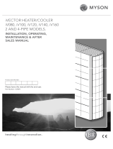
FUSE RATINGS
FUSE
PPT8AL
PPT12AL
3A
3A
6.0 Circuit Diagrams PPT8/12 AL SINGLE PHASE 230V~1N 50Hz

Calorex Heat Pumps Ltd. · The Causeway, Maldon, Essex CM9 4XD, UK · Tel: +44 (0)1621 857 171
Installation Manual
PPT8/12/16/22L/LY
Page 18
R
PPT16/22 AL SINGLE PHASE 230V~1N 50Hz
MODEL
FUSE RATINGS
FUSE
PPT16AL
PPT22AL
3A
3A
MODEL
OVERLOAD SETTING
PPT16AL
PPT22AL
23.9A
29.7A
STANDARD
HEAT PUMP
POOL PUMP
SYNCHRONISATION
CONTACTOR
3
1
4
2
(N/O)
(N/O)
A1
A2
56
(N/O)
LIVE NEUTRAL
WATER FLOW
LIGHT
WATER FLOW
SWITCH
9
8
COMPRESSOR
C
S(A)
R(P)
DELAY
TIMER T1
CONTROL FUSE
FAULT
LIGHT
MAINS LIGHT
RUN CAP
START CAP
DEFROST
FAN
SOFT
START
O/LOAD
SOFT START
THERMAL
OVERLOAD
& FAULT
LIGHT
RELAY/HARD
IF FITTED
IF
FITTED
IF FITTED
6
7
LIGHT
TERMINAL
BLOCK
SENSOR
POOL
STAT
INTERLOCK
TERMINALS
A
B
6
4
1211 10
(N/O)
(COM)
HP
SWITCH
LP
SWITCH
BREAKS ON
PRESSURE FALLING
BREAKS ON
PRESSURE RISING
L
C
H
C
(N/O)
L
C
DEFROST
STAT (N/C)
R1
7
41
(N/C) (N/O)
(COM)
(N/C)
(N/O)
4
2
(3 MINS)
A
B
R2
7
41
(N/C) (N/O)
(COM)
A
B
R3
7
41
(N/C) (N/O)
(COM)
A
B
R4
7
41
(N/C) (N/O)
(COM) 9
63
(N/C) (N/O)
(COM)
8
52
(N/C) (N/O)
(COM)
9
63
(N/C) (N/O)
(COM)
A1
A2
TIMER
(1 Hr)
15
1816
(N/C) (N/O)
(COM)
DELAY
TIMER
FAN CAP
22 23
24 26 25
6
(6 MINS)
96
(N/C)
95
COMPRESSOR
O/LOAD ALARM
T3
T2
VOLT FREE
POOL PUMP
RUN

Page 19
Calorex Heat Pumps Ltd. · The Causeway, Maldon, Essex CM9 4XD, UK · Tel: +44 (0)1621 857 171
Installation Manual
PPT8/12/16/22L/LY R
MODEL
FUSE RATINGS
FUSE
PROPAC T 8ALY
PROPAC T 12ALY
3A
3A
22 23
24 26 25
A1
A2
34
(N/O)
DEFROST LIGHT
FAN
DEFROST
STAT
1 4
2 3
REVERSING VALVE
VOLT FREE
POOL PUMP
RUN
LIVE NEUTRAL
WATER FLOW LIGHT
WATER FLOW
SWITCH
9
8
COMPRESSOR
C
S(A)
R(P)
CONTROL FUSE
FAULT
LIGHT
MAINS LIGHT
RUN CAPACITOR
SOFT
START
KIT (IF
FITTED)
CONTACTOR
SOFT START
THERMAL
OVERLOAD &
FAULT LIGHT
IF FITTED
RELAY/
HARD START
CAPACITOR (IF
FITTED)
6
7
TERMINAL
BLOCK
SENSOR
POOL STAT
INTERLOCK
TERMINALS
A
B
6
4
1211 12
(N/O)
(COM)
L P SWITCH
(BREAKS ON PRESSURE
FALLING)
L
C
H
C
(N/O)
R1
7
41
(N/C) (N/O)
(COM)
(N/C)
(N/O)
5
1
6
2
(N/O)
(N/O)
A
B
R 2
7
41
(N/C) (N/O)
(COM)
A
B
R 3
7
41
(N/C) (N/O)
(COM)
A
B
R 4
7
41
(N/C) (N/O)
(COM) 9
63
(N/C) (N/O)
(COM)
8
52
(N/C) (N/O)
(COM)
9
63
(N/C) (N/O)
(COM)
A1
A2
15
1816
(N/C) (N/O)
(COM)
DELAY TIMER
T2
(3 MINS)
DELAY TIMET
T3
(1 Hr)
DELAY TIMER
T1
(6 MINS)
H P SWITCH
(BREAKS ON PRESSURE
RISING)
POOL PUMP
SYNCHRONISATION
STANDARD
HEAT PUMP
PPT8/12 ALY SINGLE PHASE 230V~1N 50Hz

Calorex Heat Pumps Ltd. · The Causeway, Maldon, Essex CM9 4XD, UK · Tel: +44 (0)1621 857 171
Installation Manual
PPT8/12/16/22L/LY
Page 20
R
MODEL
FUSE RATINGS
FUSE
PPT16ALY
PPT22ALY
3A
3A
MODEL
OVERLOAD SETTING
PPT16ALY
PPT22ALY
23.9A
29.7A
PROPAC16/22 ALY SINGLE PHASE (230V ~ 1 N 50Hz)
22 23
24 26 25
A1
A2
34
(N/O)
1 4
2 3
VOLT FREE
POOL PUMP
RUN
96
95
COMPRESSOR
ALARM
MAINS
9
8
COMPRESSOR
C
S(A)
R(P)
RUN CAPACITOR
CONTACTOR
6
7
A
B
6
4
1211 12
(N/O)
(COM)
L
C
H
C
(N/O)
7
41
(N/C) (N/O)
(COM)
(N/C)
(N/O)
5
1
6
2
(N/O)
(N/O)
A
B
R 2
7
41
(N/C) (N/O)
(COM)
A
B
R 3
7
41
(N/C) (N/O)
(COM)
A
B
R 4
7
41
(N/C) (N/O)
(COM) 9
63
(N/C) (N/O)
(COM)
8
52
(N/C) (N/O)
(COM)
9
63
(N/C) (N/O)
(COM)
A1
A2
15
1816
(N/C) (N/O)
(COM)
DELAY TIMER
T2
(3 MINS)
(N/C)
DELAY TIMER
T3
(1 Hr)
DEFROST LIGHT
FAN
DEFROST
THERMOSTAT
REVERSING VALVE
NEUTRAL
WATER FLOW LIGHT
WATER FLOW
SWITCH
CONTROL FUSE
FAULT LAMP
MAINS LAMP
SOFT
START
KIT IF
FITTED
SOFT START
THERMAL
OVERLOAD
AND FAULT
LIGHT IF
FITTED
RELAY/
HARD START
CAPACITOR
(IF FITTED)
TERMINAL
BLOCK
SENSOR
POOL
THERMOSTAT
INTERLOCK
TERMINALS
L.P SWITCH
(BREAKS ON PRESSURE
FALLING)
R1
DELAY TIMER
T1
(6 MINS)
H.P SWITCH
(BREAKS ON PRESSURE
RISING)
POOL PUMP
SYNCHRONISATION
STANDARD HEAT
PUMP
PPT16/22 ALY SINGLE PHASE 230V~1N 50Hz
/