Page is loading ...

1
SD675650 ISSUE 6 M172 DELTA
Delta system
Owner installation manual (SD675650 issue 6)


3
SD675650 ISSUE 6 M172 DELTA
HEALTH AND SAFETY WARNING
As e dehumidifier embodies electrical and rotational equipment, ONLY competent persons
should carry out any work on is type of machine.
(SEE GUARANTEE)
HEALTH AND SAFETY WARNING ............................................4
FEATURES OF THE DELTA RANGE...........................................5
1.0 HOW THE DELTA SYSTEM WORKS ................................... 6
1.1 HOW THE AIR FLOWS THROUGH THE DELTA ................7
1.2 HOW TO USE THE DELTA ...................................................8
1.3 TOUCHSCREEN USER INTERFACE ....................................9
1.4 DATA ENTRY ...................................................................... 15
2.0 USER SETTINGS ................................................................ 16
2.1 ADVANCED SETTINGS ..................................................... 26
2.2 REMOTE ACCESS TO THE DELTA TOUCHSCREEN ...... 34
3.0 INSTALLATION .................................................................. 37
3.1 SITING, MACHINE LOCATION ......................................... 38
3.2 AIR FLOW (POOL HALL AIR) .......................................... 40
3.3 FRESH AIR AND EXHAUST AIR ...................................... 41
3.4 PLUMBING INSTALLATION ............................................. 42
3.5 ELECTROLYTIC CORROSION IN SWIMMING POOLS .. 46
3.6 ELECTRICAL CONNECTIONS .......................................... 47
3.7 ELECTRICAL INSTALLATION ........................................... 48
3.8 VOLT FREE TERMINALS AND REMOTE ACCESS ......... 49
3.9 AIR QUALITY SENSOR IF OPTION FITTED (KIT D) ..... 52
3.10 NETWORK CONNECTION .............................................. 52
3.11 BMS CONNECTION
(BUILDING MANAGEMENT SYSTEM) ................................. 53
3.12 OPTIONAL REMOTE SENSOR BOX ............................. 54
4.0 AFTER INSTALLATION ..................................................... 55
4.1 MAINTENANCE ................................................................. 57
4.2 CIRCUIT DIAGRAMS ......................................................... 58
5.0 DATA SHEET ...................................................................... 61
5.1 LPHW HEATING DATA - DELTA WITH STANDARD AIR
HEATER ..................................................................................... 62
5.2 LPHW HEATING DATA - DELTA WITH UPGRADED AIR
HEATER ..................................................................................... 63
6.0 DIMENSIONS ..................................................................... 64
7.0 DELTA CONFIGURATIONS ............................................... 78
8.0 WARRANTY CONDITIONS ............................................... 80
9.0 HEAT PUMP RECORD LOG .............................................. 81
CONTENTS
DELTA SYSTEM, OWNER INSTALLATION MANUAL (SD675650 ISSUE 6)

4 SD675650 ISSUE 6 M172 DELTA
DELTA SYSTEM OWNER INSTALLATION MANUAL
HEALTH AND SAFETY WARNING
This appliance can be used by children from eight years and above and persons wi reduced
physical, sensory or mental capabilities or lack of experience and knowledge if ey have been
given supervision or instruction concerning e use of e appliance in a safe way and understand
e hazards involved. Children should not play wi e appliance. Cleaning and maintenance shall
not be made by children wiout supervision.
This machine is classified as “NOT ACCESSIBLE TO THE PUBLIC” and erefore should be located
in a machine room and serviced by qualified personnel.
Disconnect from e mains supply and wait ree minutes before removing panels and
commencing work on is machine.
HEALTH AND SAFETY
WARNING

5
SD675650 ISSUE 6 M172 DELTA
FEATURES OF THE DELTA RANGE
The Delta range consists of nine models: 1, 2, 4, 6, 8, 10, 12, 14 and 16. All
are purpose designed and built for swimming pool use, to provide heat pump
dehumidification, heat recovery and fresh air ventilation. The recirculated air flow
increases across e range, from 2500m³/h for a Delta 1 to 12000m³/h for a
Delta 16. All Delta models are supplied as packaged air handling units wi an
integral control system and a 5.7" touchscreen controller.
Delta models offer e following features and functions:
yRobust chassis and construction specifically designed for a swimming pool
environment
yVentilation of e pool hall by main supply fan
yAutomatically regulated introduction of variable fresh air volume using a
dedicated exhaust fan and damper, set to provide a pool hall negative
pressure
yHeat pump dehumidifier for e recirculation and exhaust air flows,
incorporating heat recovery to pool water and pool hall air
yCondenser for rejection of excess recovered heat to exhaust air (Delta 4
and above only)
yIntegral control system complete wi PLC, sensors and 5.7" colour
touchscreen, providing automatic control of:
- Humidity
- Air temperature
- Pool water temperature
yComprehensive configuration, operation and fault status
yFully controlled LPHW air heater battery
yFully controlled LPHW pool water heat exchanger
yAir filtration
yOptional features
yFor duct connections, pool water and LPHW pipework positions and sizes,
please refer to drawings elsewhere in is manual.
yThe Delta range can be supplied wi many air outlet configurations, see
configuration drawings for versions available. Versions wi a bottom outlet
main supply fan include a fitting kit at includes floor adapter, flexible
ducting and securing straps to facilitate connection to floor ducting.
All Delta models contain a heat recovery heat pump dehumidifier at is
automatically controlled to remove unwanted humidity from e swimming pool
hall and provide swimming pool water heating. Heat recovery from e heat
pump is usually sucient to supply e majority of e evaporation heat losses
from e main pool water. The heat recovery will also contribute significantly
towards e hall heating requirements. The system is optimised for a swimming
pool environment and will provide eciencies upwards of 250%.
For Delta 4 and above, e heat recovery process can also be used to reject
heat to e exhaust air stream to provide cooling when e swimming pool hall
has exceeded its set temperature.
All Delta models have two fans, a main recirculating fan and a smaller exhaust
fan and are designed for connection to supply air ducting, return air ducting and
fresh air/exhaust ducting. All models use ecient, direct drive, EC fans.
All Delta models have e facility to exhaust a percentage of e recirculating
air and introduce a slightly lesser quantity of fresh air, using e heat pump to
provide heat recovery from exhaust air to fresh air. This difference provides a
slight negative air pressure wiin e swimming pool hall, helping to prevent
moisture from being driven into building fabric, and minimizing e opportunity
for e swimming pool environment migrating to oer connected rooms in e
facility.
All Delta models are fitted wi a fully controlled air heater and pool water
heater when connected to a low pressure hot water (LPHW) system. The
output of e standard heat exchangers are rated at an LPHW flow temperature
of 80°C (see data sheet on page 60). As an option, all Delta models can be
factory fitted wi a larger air heater to provide e same output at 60°C as e
standard air heater has at 80°C, to be used wi renewable technology heat
sources and condensing boilers at provide lower LPHW flow temperatures.
Provision is made for e LPHW heat source to be initiated by e Delta control
system. The LPHW heat source is not included.
All Delta models have an exhaust fan and variable fresh air damper,
automatically controlled by high humidity or temperature wiin e swimming
pool hall. As an option ey can be controlled by an air quality sensor at
measures e amount of pollutants wiin e pool hall. The Delta controller can
automatically protect e LPHW circuit from frost damage in extreme climatic
conditions. The Delta also has volt free contacts at could be used to control a
remote damper (not supplied).
All Delta models are fitted wi pairs of “volt free” terminals at provide an
interface for pool pump, heat source and setback control, as well as remote
monitoring/control of e unit. See section 3.8 Volt free terminals and remote
access for a full list of ese terminals.

6 SD675650 ISSUE 6 M172 DELTA
DELTA SYSTEM OWNER INSTALLATION MANUAL
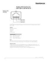
DELTA HEAT RECOVERY DEHUMIDIFIER APPLIED TO AN INDOOR SWIMMING POOL
CONDENSATE DRAIN
REFRIGERATION CIRCUIT
LPHW
SYSTEM
HEAT RECOVERED FROM MOIST POOL
HALL AIR (RETURN & EXHAUST)
UTILISED FOR HEATING POOL WATER
VISUAL FLOW INDICATOR
UTILISED FOR SENSIBLE HEATING OF POOL HALL AIR
+
+-
EXHAUST
FAN
EXHAUST AIR
FRESH AIR
MOIST RETURN AIR FROM POOL HALL
FILTRATION PUMP
FILTRATION UNIT
DEHUMIDIFIED AND HEATED SUPPLY AIR TO POOL HALL *
* A PROPORTION OF SUPPLY AIR SHOULD BE DIRECTED
OVER GLAZED SURFACES AT THE PERIMETER TO PREVENT
CONDENSATION FORMATION
SWIMMING POOL
FLOW INDICATOR OR
COMMISSIONING SET
SANITISER OR CHEMICAL
DOSING POSITION
SUPPLY
AIR FAN
RECOVERED HEAT FROM MOIST POOL HALL AIR (RETURN & EXHAUST)
NRV
1.0 HOW THE DELTA SYSTEM WORKS

7
SD675650 ISSUE 6 M172 DELTA
Delta operating on maximum dehumidification of pool air wi full heat recovery to pool water
and air. Available energy is removed from exhaust air stream. Supplementary heat, if required,
supplied by LPHW (water or air).
CONDENSATE
Return Air
Supply Air
Full Dehumidification&Heat Recovery
WARM DRY AIR
HOT DRY AIR
COOL DRY AIR
WARM HUMID AIR
Full dehumidification and heat recovery
Delta operating on light dehumidification wi full heat recovery and reduced fresh air stream –
control system automatically selects correct operating mode and damper position. LPHW heat
available when required.
CONDENSATE
Return Air
Supply Air
Light Dehumidification&Heat Recovery
WARM DRY AIR
HOT DRY AIR
COOL DRY AIR
WARM HUMID AIR
Light dehumidification and heat recovery
Delta models 4 and above provide an air conditioning facility to minimise e effects of solar gain
from larger glazed areas or very high usage. Automatic damper and mode control.
Return Air
Supply Air
CONDENSATE
Air Conditioning
WARM DRY AIR
HOT DRY AIR
COOL DRY AIR
WARM HUMID AIR
Air conditioning
Air temperature set back control is incorporated as standard in all Delta units and controlled by a
time clock. Pool hall air is dropped to a lower temperature for maximum economy. Air recircula-
tion is maintained, dampers allow low fresh air flow.
CONDENSATE
Return Air
Supply Air
Night Set Back
WARM DRY AIR
HOT DRY AIR
COOL DRY AIR
WARM HUMID AIR
Night set back
1.1 HOW THE AIR FLOWS THROUGH THE DELTA

8 SD675650 ISSUE 6 M172 DELTA
DELTA SYSTEM OWNER INSTALLATION MANUAL
TOUCHSCREEN USER
INTERFACE
POWER LIGHT
HIGH PRESSURE FAULT
RESET BUTTON
LOW PRESSURE FAULT
RESET BUTTON
1.2 HOW TO USE THE DELTA
Power light – when illuminated red, power is connected to e Delta.
Caution – e Delta system remains powered and live. Ensure e Delta
is isolated from e power supply before any servicing or electrical work
commences. When unlit, power is disconnected but remote interfaces
connected to e Delta from oer systems may still be live.
Eernet port – for connection to a local area network. (See page 53.)
Touchscreen user interface – display of operating condition and access to
settings. (See page 9.)
High pressure fault reset button and low pressure fault reset button – reset
buttons for LP/HP Fault. (See pages 11 and 19.)
ETHERNET PORT

9
SD675650 ISSUE 6 M172 DELTA
1.3 TOUCHSCREEN USER INTERFACE
The Delta is controlled by an integral controller wi a touchscreen user
interface. All e settings of e Delta are available via e touchscreen.
If e screen is blank, touch once to activate.
Coloured buttons and parameters wi a white background can be modified,
except where locked by e User Security settings. Grey buttons and
parameters wi a grey background cannot be modified. (See page 23.)
Pressing e + button shows e second home screen. Pressing e home button returns to e first home screen.
Home screens
These two screens display current operating conditions and main controls. Functions on e home screens can be modified if allowed by e User Security Mode
settings. (See page 23.)
First home screen
Second home screen

10 SD675650 ISSUE 6 M172 DELTA
DELTA SYSTEM OWNER INSTALLATION MANUAL
FIRST HOME SCREEN
POOL HALL
HUMIDITY
POOL HALL AIR
TEMPERATURE
1. Pool hall relative humidity (%RH)
Number shows current measurement. Outer ring shows current
measurement (blue bar) in relation to current setting (red arrow). Press
the centre to change humidity setting.
Key to lights
Purple (flashing) – waiting for compressor delay timer to elapse.
Purple (solid) – dehumidification operating (compressor running).
Blue (solid) – air cooling mode operating (compressor running).
2. Pool hall air temperature (°C)
Number shows current measurement. Outer ring shows current
measurement (blue bar) in relation to current Occupied mode setting (red
arrow). Press the centre to change temperature setting.
Key to lights
Yellow (solid) – air heating via LPHW operating.
Blue (solid) – air cooling mode operating.
3. Pool water temperature (°C)
Number shows current measurement. Outer ring shows current
measurement (blue bar) in relation to current setting (red arrow). Press
the centre to change temperature setting.
Key to lights
Yellow (solid) – pool water heating via LPHW operating.
Orange (flashing) – water heating calling for the pool pump to run.
4. Swimming icon
Press to access time clock settings. The swimming icon shows that the
Delta is in the Occupied mode. A red cross indicates that the Delta is in
Unoccupied mode.
Functions on e first home screen can be modified if allowed by e User
Security Mode settings. (See page 23.)
POOL WATER
TEMPERATURE
OCCUPIED/
UNOCCUPIED
TIME CLOCK
SETTINGS
INDICATOR
LIGHTS
ON/STANDBY
BUTTON

11
SD675650 ISSUE 6 M172 DELTA
LIGHTS AND STANDBY SWITCH
Indicator lights
Pressing is area when an alarm is active displays e "Alarms" screen.
Defrost light
Light blue (solid) – defrost is active. Defrosting is a normal function to remove ice from e heat
recovery surfaces, which may be required when e pool hall air temperature drops below 20°C.
Dark blue (solid) – frost protection is active. (See page 27.)
Light blue and dark blue (flashing) - defrost and frost protection are active.
Fault light
Red (solid) – fault wi e refrigeration system.
Orange (solid) – fault wi e main fan.
Yellow (solid) – fault wi e exhaust fan.
Dark blue (solid) – no flow, fault wi e pool pump.
Light blue (flashing) - pool water heat exchanger overheat protection.
Purple (solid) – fault wi e compressor.
There can be more an one fault. All faults should be investigated. (See page 19.)
Alarm light
Red (solid) – fire alarm is active.
Pink (solid) - pool water heat exchanger overheat protection.
Orange (solid) - fan pressure alarm (if option fitted).
Yellow (solid) – filter dirty warning (if option fitted).
Dark blue (solid) – air quality sensor is overriding fresh air control (if option fitted).
Light blue (flashing) – 'Dance Hall Mode' is active. (See page 21.)
Purple (solid) – clock reset required.
Purple (solid) + 'S' – service is overdue. Contact e Danerm Group to arrange servicing of e
Delta.
Standby switch
Green and white – ON.
Delta is powered and operating according to e control system settings.
Red and white – user Standby.
Delta is powered but not operating. The Delta has been put into Standby via e user touchscreen. See
caution below. To enable e Delta, press e red touchscreen button.
Orange and black – remote Standby.
Delta is powered but not operating. The Delta has been put into Standby via e remote On/Off control
interface. See caution below. To enable e Delta, change e remote interface from Off to On.
Red and black – user and remote Standby.
Delta is powered but not operating. The Delta has been put into Standby via e user touchscreen AND
e remote on/off control interface. See caution below. To enable e Delta, press e red touchscreen
button AND change e remote interface from Off to On.
There is a five second delay before e Delta starts.
Caution: in all Standby modes, e Delta system remains powered and live. Ensure e Delta is isolated
from e power supply before any servicing or electrical work commences. See power light on page 8.
Following a power interruption e Delta will eier remain in Standby or attempt to restart automatically,
according to e user setting. See page 29.

12 SD675650 ISSUE 6 M172 DELTA
DELTA SYSTEM OWNER INSTALLATION MANUAL
SECOND HOME SCREEN
5. Fresh air setting
AUTO (recommended) allows automatic control of fresh air quantity
according to control system settings. MIN allows experienced operators
to override automatic fresh air control and force e minimum fresh air
quantity. MAX allows experienced operators to override automatic fresh
air control and force e maximum fresh air quantity.
6. Occupied/Unoccupied override
Normally set to AUTO, allowing e time clock to control e Occupied
and Unoccupied periods of e Delta. The le-hand button sets e
Delta into Occupied mode. The right-hand button sets e Delta into
Unoccupied mode. If remote control of Occupied/Unoccupied is to be
used, is control should be set to Unoccupied. (See page 14.)
7. User settings
Allows e user to change e settings of e Delta (user pin code
required to access).
8. Function button
Green – ON. Enables e Delta to operate wi full function.
Red – OFF. Water heating only mode. Note: There is a 60 minute delay
when water heating is required.
9. Air-conditioning mode button
Normally set to A/C ON, so e Delta provides air-conditioning when
required. When switched to OFF, no air-conditioning will be allowed.
Note: Fresh air will still be controlled irrespective of air conditioning mode
selection.
10. Air/Water priority button
Switches e Delta between priority given to heating e pool water
(recommended for most pools) or air.
11. Service engineer settings
These settings are for Danerm Group service engineers and are
password protected.
Functions on e second home screen can be modified if allowed by e User
Security Mode settings. (See page 23.)
USER SETTINGS
– PIN CODE
REQUIRED
SERVICE ENGINEER
SETTINGS –
PASSWORD
PROTECTED
FRESH AIR SETTING
BUTTONS
OCCUPIED/
UNOCCUPIED
OVERRIDE
FUNCTION
BUTTON
AIR-
CONDITIONING
BUTTON (DELTA
4 AND ABOVE
ONLY)
HEAT
RECOVERY
PRIORITY
SWITCH

13
SD675650 ISSUE 6 M172 DELTA
It is essential to control e pool hall conditions 24 hours per day and, once
commissioned, your Delta should never be turned off if you are to avoid
discomfort and/or expensive building damage due to humidity. It is a common
mistake to believe at by turning e Delta off will save running costs. This is
not true. Turning e Delta off turns off all e energy recovery it provides, and
your swimming pool will cost you more to operate overall.
The energy usage and environment in a swimming pool are a delicate balance
and your Delta has been selected to operate at very specific conditions. The
most important principle in a swimming pool is e difference between e air
and water temperatures. For bo economy and comfort, it is good practice
to keep e air temperature in e pool hall 1-2°C above e pool water
temperature while e cover is removed (Occupied Mode). A normal humidity
target in a pool hall is 60%RH. These settings should correspond to e original
design parameters for e project. Unless oer conditions were specifically
requested at e time e system was designed, e most common conditions
used in indoor pools are:
yWater temperature 28°C-30°C
yAir temperature 29°C-30°C
yRelative Humidity 60%RH
Changing e settings may result in high power consumption or less effective
control of e environment. If you:
yIncrease e water temperature – evaporation from e swimming pool
water will increase, running costs will increase, and e likelihood of
condensation will increase.
yReduce e water temperature – evaporation from e swimming pool
water will reduce, running costs will reduce.
yIncrease e air temperature – evaporation from e swimming pool water
will reduce, running costs usually reduce.
yReduce e air temperature – evaporation from e swimming pool water
will increase, running costs will increase, and e likelihood of discomfort
and condensation will increase.
yIncrease e humidity – running costs will reduce, but comfort will worsen,
and e likelihood of condensation will increase.
yReduce e humidity – running costs will increase, but may not improve
comfort, nor reduce e likelihood of condensation.
If you do find it necessary to adjust settings, firstly ensure at e control
system sensors are measuring accurately by using a calibrated ermometer
and always maintain e air 1°C higher an water temperature. The settings for
humidity, air temperature and pool temperature can be changed by touching
e centre of e corresponding parameter. A keypad appears. (See page 10.)
Unless e Delta has been specifically chosen for e purpose, do not
operate wi e air temperature below e water temperature when
e cover is removed.
The only exception is when a floating cover is in place on e pool (Unoccupied
Mode).
HUMIDITY AND TEMPERATURE SETTINGS
POOL HALL
HUMIDITY
(%RH)
POOL HALL AIR
TEMPERATURE
(°C)
POOL WATER
TEMPERATURE
(°C)

14 SD675650 ISSUE 6 M172 DELTA
DELTA SYSTEM OWNER INSTALLATION MANUAL
POOL OCCUPIED SYMBOL
POOL UNOCCUPIED SYMBOL
Whenever a floating pool cover is in use, e cover suppresses evaporation and
heat loss, so it is not necessary to maintain e air temperature higher an e
pool water. Significant running cost reductions can be achieved by reducing
e air temperature. Do not reduce e air temperature wiout a pool cover in
place.
Normal operation, wi e cover removed, is called Occupied Mode. Reduced
air temperature operation, wi e cover in place, is called Unoccupied Mode.
It is expected at e pool will be covered during Unoccupied periods, to
conserve energy and minimise evaporation. If Unoccupied Mode is used while
e cover is removed, increased power consumption and loss of ideal conditions
may result. The integral time clock on e control system allows fixed times to
be set for when e cover will be in place. If you have an automatic pool cover,
it may be possible to connect is to e Delta as described in section 3.8, to
automatically set Occupied and Unoccupied modes when e cover is moved.
The Delta operates in eier Occupied or Unoccupied Mode according to:
yUser time period settings
yUser override button
yRemote system connected to e interface terminals
In Occupied Mode, all functions operate according to User Settings.
In Unoccupied Mode, e following functions change:
yPool hall air temperature setting reduced to e unoccupied temperature
setting (sometimes called night set back). The pool hall will not be cooled
to is temperature, but if heating is required, it will only heat to is lower
temperature setting.
yRefrigerated air-conditioning does not operate (Delta 4 upwards only). The
economiser will operate, if enabled.
yFresh air is reduced to minimum, unless e user fresh air setting or air
quality sensor (if fitted) activate maximum fresh air.
yWhen water heating is required, ere is a delay of 60 minutes (adjustable)
in activating e pool pump and heating e water.
Going away for extended periods
Your Delta system, once commissioned, should never be turned off completely.
Even a cold pool will allow moisture to evaporate into e environment and if
is is not dealt wi expensive building damage may follow. If you go away for
extended periods or wish to take e pool out of commission, en you should
follow e following procedure:
Use a good swimming pool cover on e pool to minimise evaporation.
ySet e water temperature at 10°C
ySet e air temperature to 12-15°C
yLeave e humidity setting at 60-65%RH
yLeave e time clock setting in Unoccupied Mode
These settings will minimise energy usage whilst providing maximum
protection for your building.
OCCUPIED AND UNOCCUPIED

15
SD675650 ISSUE 6 M172 DELTA
Coloured buttons and parameters wi a white background can be modified,
except where locked by e User Security settings. Grey buttons and
parameters wi a grey background cannot be modified.
To change parameters wi a white background, press e parameter.
A keypad appears for number entry – an alphabet appears for text entry.
The keypad for entering numeric parameters is shown below. The parameter to
be modified is shown at e top. The allowable range at e parameter can
be changed between is shown undernea.
1.4 DATA ENTRY
TYPE IN THE REQUIRED
SETTING
BACKSPACE KEY
MOVES THE CURSOR
TO THE RIGHT
CLEARS SETTING
SAVES THE SETTING
AND RETURNS TO THE
SETTINGS SCREEN
ALLOWABLE RANGE
LEAVES THE SCREEN
WITHOUT SAVING
MOVES THE CURSOR
TO THE LEFT
If Security Mode is enabled (see p23) some functions may not be accessible
from e home screens. Functions at are not accessible are shown wi
hashed lines. In e examples shown below all functions have restricted access
apart from e Occupied/Unoccupied override.
SECURITY MODE

16 SD675650 ISSUE 6 M172 DELTA
DELTA SYSTEM OWNER INSTALLATION MANUAL
2.0 USER SETTINGS
The main User Settings screens are protected by a PIN code. User Settings can be accessed by pressing e cog button on e second Home screen.
Controller Clock Occupied/Unoccupied periods Alarms Set Points and Switches
Dance Hall Mode Language User Security Data Monitoring
USER SETTINGS
INSERT THE PIN AND PRESS
THE ARROW
The default PIN for accessing
e User Settings is 6016.
The Danerm Group
recommend is is changed.
Security options and record of
PIN. (See page 23.)
THE SETTINGS
SCREEN APPEARS
Settings

17
SD675650 ISSUE 6 M172 DELTA
To change e date or time, press e white box wi e number to be
changed. Press Set Clock when e date and time are correct.
Press e Arrow to return to e User Settings screen or if noing else needs
to be changed, press Home to return to e Home screen.
Once e time and date have been set is should not need to be done again
as long as e Delta is On or in Standby. The clock has a battery reserve fitted
which, when charged, has an operating time of ree days so at isolating e
Delta unit for short periods will not reset e clock. It may be necessary to set
e clock if e Delta is isolated from power or if ere is an interruption to e
power supply which lasts longer an ree days.
DAYLIGHT SAVING TIME
This button is red when
daylight saving is disabled
and green when daylight
saving is enabled.
Press e button to
manually toggle between
enabled and disabled.
Default factory settings are UK daylight saving periods and will change
automatically on e dates set in is screen. Where e daylight saving times
and dates are different to ose shown, ey can be changed here.
Press e Arrow to return to e User Settings screen or if noing else needs
to be changed, press Home to return to e Home screen.
CONTROLLER CLOCK
Press is button on e Settings menu.
PRESS SET CLOCK
Arrow icon
Return to
User Settings
Home icon
Return to
Home screen
Arrow icon
Return to
User Settings
Home icon
Return to
Home screen

18 SD675650 ISSUE 6 M172 DELTA
DELTA SYSTEM OWNER INSTALLATION MANUAL
Press e le side of
e colon to change e
hour setting.
Press e right side of
e colon to change e
minute setting.
This screen can also be accessed from e first Home screen if e User Security
settings are set to allow access.
When one of e time settings is touched, e keypad appears to allow e
parameter to be changed. Any time wi a white background can be changed.
There are two periods per day, A and B. Days can be set individually, or copied
to e whole week. If A and B periods overlap, priority is given e Occupied
period. If one Occupied period is required, period B can be disabled.
The current Occupied air temperature and e Unoccupied air temperature
settings are shown. The Unoccupied setting is set as e difference between
e two, which can be changed. In e example above, e Occupied air
temperature setting is 28.0°C and e Unoccupied air temperature setting is
4.5°C below at, 23.5°C. The minimum night set back temperature controlled
by e Delta is 22°C. This means at e greatest difference allowed is 6°C.
Press e Home button to return to e User Settings screen.
TIME CLOCK
Press is button on e Settings menu.
Home icon
Return to
Home screen
If a second occupied period is
required enable is button.
Times in e second period
can be entered in B.
The times for e rest of
e week can be copied by
pressing is button.
08:00

19
SD675650 ISSUE 6 M172 DELTA
ALARMS
Press is button on e Settings menu.
The Alarms screen displays warnings or faults wi e Delta, indicated by a red
highlight. The example above indicates at ere is a problem wi e pool
water flow rate at should be investigated.
The Main Filter Blocked and Exhaust Filter Blocked alarm text is always shown,
but will only function if e optional filter monitoring sensors are fitted in e
Delta. When fitted, gauge symbols are shown beside e text for ese alarms
(see below). When shown, is area can be pressed to access a visualisation of
e sensor measurements.
Arrow icon
Return to
User Settings
Home icon
Return to
Home screen

20 SD675650 ISSUE 6 M172 DELTA
DELTA SYSTEM OWNER INSTALLATION MANUAL
SET POINTS AND SWITCHES
Press is button on e Settings menu.
Arrow icon
Return to
User Settings
Home icon
Return to
Home screen
This screen duplicates settings on e Home screens. If functions on e Home
screens are disabled by e User Security settings, ey may be accessed here.
Press e Arrow to return to e User Settings screen or if noing else needs
to be changed press Home to return to e Home screen.
/