Page is loading ...

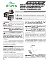
Installer’s Guide
ALL phases of this installation must comply with NATIONAL, STATE AND LOCAL CODES
IMPORTANT – This Document is customer property and is to remain with this unit. Please return to service information pack
upon completion of work.
WARNING
!
WARNING (Medium/high pressure)
Contains Refrigerant!
System contains oil and refrigerant under high pressure.
Recover refrigerant to relieve pressure before opening the
system. See unit nameplate for refrigerant type. Do not
use non-approved refrigerants, refrigerant substitutes, or
refrigerant additives.
Failure to follow proper procedures or the use of non-
approved refrigerants, substitutes, or refrigerant additives
could result in death, serious injury, or equipment damage.
B. APPLICATION INFORMATION
1. FURNACE AND COIL
The coil MUST BE installed downstream (in the outlet air) of
the furnace.
These coils fit the 14½", 17½", 21, and 24½" width furnaces in
vertical upflow and downflow applications.
Coils are equipped with a high temperature composite drain
pan and do not require a heat shield when installed with
Trane, American Standard, RunTru or Ameristar gas or elec-
tric furnaces. Do NOT install with OIL or DRUM type furnaces.
IMPORTANT:
Review your installation requirements. Check the table on
the outline drawings and note all dimensions for your coil
before beginning the installation.
2. INDOOR UNIT AIRFLOW
Indoor unit must provide the required airflow for the heat pump
or cooling combinations approved for these coils.
Figure 1
Uncased Vertical Aluminum Upflow Coils
4AXAA001BS3HAA
4AXAB002BS3HAA
4AXAA003BS3HAA
4AXAB004BS3HAA
CAUTION
!
This coil is pressurized with 35 psi (+/- 5 psi) of nitrogen.
If no pressure is released, check for leaks.
18-AD44D1-1B-EN
4AXAA005BS3HAA
4AXAB006BS3HAA
4AXAB007BS3HAA
4AXAB008BS3HAA
4AXAC009BS3HAA
4AXAB010BS3HAA
4AXAC011BS3HAA
4AXAD012BS3HAA
WARNING
!
This product can expose you to chemicals including
lead, which are known to the State of California to case
cancer and birth defects or other reproductive harm.
For more information go to www.P65Warnings.ca.gov
A. GENERAL
These coils are designed for use in combination with a heat pump
or cooling outdoor section using R-410A REFRIGERANT. They
may be combined with a Gas or Electric Furnace for a complete
system that will provide maximum comfort and energy efficiency
during the entire year.
The *4AXA equipment has been evaluated in accordance with
the Code of Federal Regulations, Chapter XX, Part 3280 or the
equivalent. “Suitable for Mobile Home use” The height of the
Furnace, Coil and discharge duct work must be 7 ft. or less.
Inspect the coil for shipping damaged. Notify the transportation
company immediately if the coil is damaged.

2 18-AD44D1-1B-EN
Installer’s Guide
IMPORTANT:
Do not unseal refrigerant tubing until ready to t
refrigerant lines.
1. Release the entire holding pressure by depressing the
schrader core.
2. Using tubing cutters, remove the least amount of the
refrigerant stub tubes as possible.
3. Ream and deburr both liquid and vapor tubes.
4. Run the refrigerant tubing into the vapor stub tube. Connect
the liquid lines using a 3/8" copper coupling.
5. Make sure copper equalizer lines do NOT touch aluminum.
AIRFLOW
Downflow Configuration
E. INSTALLING / BRAZING REFRIGERANT LINES
CAUTION
!
Do NOT open refrigerant valve at the outdoor unit until the
refrigerant lines and coil have been brazed, evacuated,
and leak checked.
1. The following steps are to be considered when installing the
refrigerant lines:
a. Determine the most practical way to run the lines.
b. Consider types of bends to be made and space
limitations.
c. Route the tubing making all required bends and properly
secure the tubing before making final connections.
C. RECOMMENDATION
If a coil is part of the total system installation, use the Installer’s
Guide packaged with the furnaces, and outdoor sections, and
thermostat for physically installing those components.
D. DOWNFLOW INSTALLATION
CAUTION
!
Condensate water blow-off could occur in downflow
installations in high humidity applications. Please ensure
that the following instructions are followed to ensure proper
operation.
To set up coils for downflow application, install the two 3” wide
by 16” long galvanized metal plates on the outside of the coil,
against the fins on each side of the coil as shown in Figure 2.
These plates are supplied with the coil.
Do NOT exceed 350 cfm/ton of airflow for downflow applications
3 ton or greater.
CAUTION
!
Do NOT install coils with any OIL or DRUM type furnaces.
F. TXV BULB HORIZONTAL MOUNTING
The orientation and location of the TXV bulb has a major
influence on the system performance.
It is recommended that the TXV bulb be installed parallel to
the ground (on a horizontal plane). The bulb position must be
at 2 o'clock or 10 o'clock. Figure 4 shows the recommended
position for the TXV bulb installation in the horizontal plane.
The TXV sensing bulb SHOULD be mounted on the suction
line approximately 6" away from outlet tubes of the circuit
using the metal clamp provided. Should NOT be placed near
any bends. In order to obtain a good temperature reading and
correct superheat control, the TXV sensing bulb must conform
to ALL the following criteria:
1. The sensing bulb MUST be in direct and continuous
contact with the suction line.
2. The sensing bulb MUST be mounted at the 2 o'clock or 10
o'clock position as shown in Figure 4.
3. The sensing bulb MUST be insulated from surrounding air.
A properly mounted sensing bulb will prevent false readings
caused by liquid refrigerant that may have formed inside the
suction/vapor line. Insulation will protect the sensing bulb from
false readings due to contact with warm air.
Figure 2
SENSING BULB
SUCTION LINE
Bulb position at
2 o’clock or
10 o’ clock Figure 4
Figure 3A Figure 3B
UPFLOW APPLICATIONS
NOTE: Cabinet will be eld provided.
DOWNFLOW APPLICATIONS

18-AD44D1-1B-EN 3
Installer’s Guide
J. CLEANING THE COIL
The inside and outside of the coil can be easily cleaned with a
brush and vacuum.
CAUTION
!
If the TXV sensing bulb is mounted vertically; the capillary
MUST be directed upwards. The bulb must be mounted on
the wall opposite to that being directly hit by the refrigerant
and oil leaving the distributor tubes.
G. TXV BULB VERTICAL MOUNTING
As recommended in Section F, the TXV sensing bulb should
be mounted in a horizontal plane in relation to the suction/
vapor line. However, some installation configurations may
require that the sensing bulb be mounted vertically. In this
instance, place the bulb opposite the piping wall being hit
by refrigerant and oil leaving the distributor tubes, and with
capillary tubes directed upwards as shown in Figure 5.
Refrigerant &
Oil Flow
Direct Capillary
Tube Upwards
Metal
Strap
Sensing Bulb location
on pipe wall opposite
to that being hit by
refrigerant and
oil leaving the
distributor tubes
Suction
Line
Figure 5
H. LEAK CHECK
1. Using a manifold gauge, connect an external supply of dry
nitrogen to the gauge port on the liquid line.
2. Pressurize the connecting lines and indoor coil to 150 PSIG
maximum.
3. Leak check brazed line connections using soap bubbles.
Repair leaks (if any) after relieving pressure.
4. Evacuate and charge the system per the instructions
packaged with the outdoor unit.
I. CONDENSATE DRAIN PIPING
Condensate drain connections are located in the drain pan at
the bottom of the coil assembly. The female threaded fitting
protrudes outside of the assembly for external connection. A
field fabricated trap is not required for proper drainage due to the
positive pressure of the furnace; however, it is recommended to
prevent efficiency loss of conditioned air.
1. The drain hole in the drain pan must be cleared of all insulation.
2. Insulate the primary drain line to prevent sweating where
dew point temperatures may be met. (Optional depending
on climate and application needs)
3. Connect the secondary drain line to a separate drain line
(no trap is needed in this line).
4. Install coils with the drain pan and/or casing on a flat, level
surface. Slope the coil 1/4” towards the drain. Condensate
lines must be installed in accordance with building codes.
PRESSURE DROP CHARACTERISTICS FOR 4AXA COOLING AND HEAT PUMP COILS
WET COIL STATIC PRESSURE DROP (INCHES OF WATER COLUMN) @ VARIOUS CFM
600 800 1000 1200 1400 1600 1800 2000 2200
4AXAA001BS3HAA
4AXAB002BS3HAA 0.24 0.3 0.54
4AXAA003BS3HAA
4AXAB004BS3HAA 0.22 0.3 0.44
4AXAA005BS3HAA
4AXAB006BS3HAA 0.26 0.4 0.46
4AXAB007BS3HAA 0.23 0.29 0.4
4AXAB008BS3HAA
4AXAC009BS3HAA 0.3 0.35 0.45
4AXAB010BS3HAA
4AXAC011BS3HAA
4AXAD012BS3HAA
0.29 0.29 0.3 0.37 0.34
K. PRESSURE DROP TABLE

4 18-AD44D1-1B-EN
Installer’s Guide
Outline Drawing for 4AXAA001BS3HAA, 4AXAB002BS3HAA, 4AXAA003BS3HAA, 4AXAB004BS3HAA, 4AXAA005BS3HAA,
4AXAB006BS3HAA, 4AXAB007BS3HAA, 4AXAB008BS3HAA, 4AXAC009BS3HAA, 4AXAB010BS3HAA,
4AXAC011BS3HAA, 4AXAD012BS3HAA (All dimensions are in inches)
HIGH TEMP COMPOSITE
HIGH TEMP COMPOSITE
HIGH TEMP COMPOSITE
HIGH TEMP COMPOSITE
HIGH TEMP COMPOSITE
HIGH TEMP COMPOSITE
HIGH TEMP COMPOSITE
HIGH TEMP COMPOSITE
HIGH TEMP COMPOSITE
HIGH TEMP COMPOSITE
HIGH TEMP COMPOSITE
HIGH TEMP COMPOSITE
PLUGGED
SECONDARY
DRAIN 3/4" NPT
PLUGGED
SECONDARY
DRAIN 3/4" NPT

18-AD44D1-1B-EN 5
Installer’s Guide
Is subcoolingatthe
outdoor unitbetween
8to12F?
Troubleshooting Indoor TXV/Cooling Mode
NO
YES Is superheat
< 5F? YES
Correctair
flow
problem
Is air flow at least
350CFM perton?
YES
NO
Removesensing bulb from the
suction line. Measure superheat
at indoor coil while holdingthe
bulb in barehandfor oneminute.
Does superheat decrease?
Measure superheatat indoorcoil
whileplacing thebulbinanice
andwater bath forone minute.
Does superheatincrease?
YES
Replace the
TXV
TXVisOK
NO
Is superheat
<25F? YES
NO
Is indoor
temperature more
than 85F?
NO
Is subcooling less
than 8F?
YES
Confirmthatcharge
is correct andlook
for dirty or restricted
outdoorcoil.
Confirmthat
charge is
correct.
NO
Beforestarting, insurethe
blower wheel,indoor and outdoor
coils areclean.
Is the liquid line
temperature at indoor
coilwithin8Fofoutdoor
liquid line temperature?
YES
Verify lineset is
sizedproperly
for application
NO
The system is runningat max
capacity andthis may be
causingthe High superheat.
Wait until indoortemperature
is lessthan80F andcheck
superheat again.
YES
YES
VerifyInlet screen
of inlettube
assembly is clear
NO
NO
of debris, if inlet
screen is present.
VerifyInlet screen
of inlettube
assembly is clear
of debris, if inlet
screen is present.

6 18-AD44D1-1B-EN
Installer’s Guide
Notes

18-AD44D1-1B-EN 7
Installer’s Guide
Notes

The manufacturer has a policy of continuous data improvement and it reserves the right to change design and specifications without notice. We are
committed to using environmentally conscious print practices.
© 2023
18-AD44D1-1B-EN 14 Mar 2023
Supersedes 18-AD44D1-1A-EN (November 2022)
About Trane and American Standard Heating and Air Conditioning
Trane and American Standard create comfortable, energy efficient indoor environments for residential applications.
For more information, please visit www.trane.com or www.americanstandardair.com
/