5
Heat Controller CCG / VCG / MCG Coils
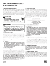
Fig. 3. Recommended location of the TXV bulb in a
horizontal orientation
5) The sensing bulb MUST be mounted above and be-
tween the 4 and 8 o’clock position on the circumfer-
ence of the suction line.
6) The sensing bulb MUST be insulated from outside air.
The mounting location and insulation guards THE sens-
ing bulb from false reading due to hot outside air or liquid
refrigerant formed inside the suction/vapor line.
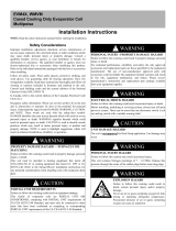
As recommended earlier, the TXV sensing bulb should be
mounted in a horizontal plane in relation to the suction/va-
por line. However, in case such a mounting is not feasible
and the sensing bulb has to be mounted vertically; then
place the bulb as shown in Fig. 4.
Fig. 4. Figure showing the sensing bulb mounted in a
vertical orientation
If the TXV sensing bulb is mounted vertically; the capillary
MUST be directed upwards. The bulb must be mounted
on the wall opposite to that being directly hit by the refrig-
erant and oil leaving the distributor tubes.
IO-123070 Effective 04-15-13
TXV BULB POSI TI ON
4 O' CLOCK OR
8 O' CLOCK
METAL STRAP
SUCTION/ VAPOR LI NE
Fig.3. Recommended location of the TXV bulb in a
horizontal orientation
5) The sensing bulb MUST be mounted above and
between the 4 and 8 o’clock position on the
circumference of the suction line.
6) The sensing bulb MUST be insulated from
outside air.
The mounting location and insulation guards THE
sensing bulb from false reading due to hot outside air or
liquid refrigerant formed inside the suction/vapor line.
As recommended earlier, the TXV sensing bulb should
be mounted in a horizontal plane in relation to the
suction/vapor line. However, in case such a mounting is
not feasible and the sensing bulb has to be mounted
vertically; then place the bulb as shown in Fig.4.
Fig.4. Figure showing the sensing bulb mounted in a
vertical orientation
If the TXV sensing bulb is
mounted vertically; the capillary MUST be directed
upwards. The bulb must be mounted on the wall
opposite to that being directly hit by the refrigerant and
oil leaving the distributor tubes.
Field – Installed Expansion Valve Coils
Remove the valve identification sticker from the valve
and place it adjacent to the Aspen model number on
unit name plate.
When installing an expansion valve, it is not necessary
to remove all the access panels and slide the coil out of
the housing.
1) Disassemble the flowrator body using two
wrenches. Unscrew the body with a counter-
clockwise motion.
2) Replace the white Teflon seal in place (located
between the halves).
3) Remove the existing flowrator piston using a
small wire or pick.
4) Inspect the TXV box to confirm that the valve is
compatible with the refrigerant in the system.
5) Remove the valve from the box and note the
location of the inlet side (threaded male port)
and the outlet side (female swivel nut port).
6) After ensuring that the white Teflon seal is still
in place inside the flowrator body, screw the
female swivel nut onto the flowrator body.
7) Place the attachment nut on the liquid line.
8) Braze the stub-out portion to the liquid line and
let cool.
Do not attempt to touch the braze
joint while hot. Touching it may cause sever burns.
9) Remove the additional white Teflon seal ring
from the box and place on the shoulder just
inside the inlet port. Screw the nut attached to
the stub-out portion of the flowrator body onto
the inlet port of the TXV.
10) Tighten all connections taking care to use
proper back up.
Some Aspen coils come with a Schrader valve on the
suction line. If a Schrader port is present
11) Remove valve stem from the Schrader port
mounted on the suction line
12) Screw flare nut on TXV equalization tube in to
the Schrader valve stem
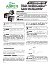
Typical expansion valve assembly is shown below in
Fig. 5.
Using a non-bleed expansion
valve may require the use of a hard-start kit. Follow the
outdoor unit manufacturer’s guidelines.
IO-123070 Effective 04-15-13
TXV BULB POSI TI ON
4 O' CLOCK OR
8 O' CLOCK
METAL STRAP
SUCTION/ VAPOR LI NE
Fig.3. Recommended location of the TXV bulb in a
horizontal orientation
5) The sensing bulb MUST be mounted above and
between the 4 and 8 o’clock position on the
circumference of the suction line.
6) The sensing bulb MUST be insulated from
outside air.
The mounting location and insulation guards THE
sensing bulb from false reading due to hot outside air or
liquid refrigerant formed inside the suction/vapor line.
As recommended earlier, the TXV sensing bulb should
be mounted in a horizontal plane in relation to the
suction/vapor line. However, in case such a mounting is
not feasible and the sensing bulb has to be mounted
vertically; then place the bulb as shown in Fig.4.
Fig.4. Figure showing the sensing bulb mounted in a
vertical orientation
If the TXV sensing bulb is
mounted vertically; the capillary MUST be directed
upwards. The bulb must be mounted on the wall
opposite to that being directly hit by the refrigerant and
oil leaving the distributor tubes.
Field – Installed Expansion Valve Coils
Remove the valve identification sticker from the valve
and place it adjacent to the Aspen model number on
unit name plate.
When installing an expansion valve, it is not necessary
to remove all the access panels and slide the coil out of
the housing.
1) Disassemble the flowrator body using two
wrenches. Unscrew the body with a counter-
clockwise motion.
2) Replace the white Teflon seal in place (located
between the halves).
3) Remove the existing flowrator piston using a
small wire or pick.
4) Inspect the TXV box to confirm that the valve is
compatible with the refrigerant in the system.
5) Remove the valve from the box and note the
location of the inlet side (threaded male port)
and the outlet side (female swivel nut port).
6) After ensuring that the white Teflon seal is still
in place inside the flowrator body, screw the
female swivel nut onto the flowrator body.
7) Place the attachment nut on the liquid line.
8) Braze the stub-out portion to the liquid line and
let cool.
Do not attempt to touch the braze
joint while hot. Touching it may cause sever burns.
9) Remove the additional white Teflon seal ring
from the box and place on the shoulder just
inside the inlet port. Screw the nut attached to
the stub-out portion of the flowrator body onto
the inlet port of the TXV.
10) Tighten all connections taking care to use
proper back up.
Some Aspen coils come with a Schrader valve on the
suction line. If a Schrader port is present
11) Remove valve stem from the Schrader port
mounted on the suction line
12) Screw flare nut on TXV equalization tube in to
the Schrader valve stem
Typical expansion valve assembly is shown below in
Fig. 5.
Using a non-bleed expansion
valve may require the use of a hard-start kit. Follow the
outdoor unit manufacturer’s guidelines.
Field – Installed Expansion Valve Coils
Remove the valve identication sticker from the valve and
place it adjacent to the model number on unit name plate.
When installing an expansion valve, it is not necessary to
remove all the access panels and slide the coil out of the
housing.
1) Disassemble the owrator body using two wrenches.
Unscrew the body with a counter-clockwise motion.
2) Replace the white Teon seal in place (located be-
tween the halves).
3) Remove the existing owrator piston using a small
wire or pick.
4) Inspect the TXV box to conrm that the valve is com-
patible with the refrigerant in the system.
5) Remove the valve from the box and note the location
of the inlet side (threaded male port) and the outlet
side (female swivel nut port).
6) After ensuring that the white Teon seal is still in
place inside the owrator body, screw the female
swivel nut onto the owrator body.
7) Place the attachment nut on the liquid line.
8) Braze the stub-out portion to the liquid line and let
cool.
Do not attempt to touch the braze joint while hot. Touching
it may cause sever burns.
9) Remove the additional white Teon seal ring from the
box and place on the shoulder just inside the inlet
port. Screw the nut attached to the stub-out portion of
the owrator body onto the inlet port of the TXV.
10) Tighten all connections taking care to use proper
back up.
Some coils come with a Schrader valve on the suction
line. If a Schrader port is present
11) Remove valve stem from the Schrader port mounted
on the suction line
12) Screw are nut on TXV equalization tube in to the
Schrader valve stem
Typical expansion valve assembly is shown below in Fig. 5.
Using a non-bleed expansion valve may require the use
of a hard-start kit. Follow the outdoor unit manufacturer’s
guidelines.
!
CAUTION
!
WARNING
!
CAUTION