Trane 4PXFH004BC3HHA Installation guide

Category
Split-system air conditioners
Type
Installation guide

The Trane 4PXFH004BC3HHA is a horizontal, flat "cased" coil designed for use as cooling only or in combination with a heat pump outdoor section. It features a durable construction with copper/aluminum coils, a compact design for easy installation, and a variety of features to enhance performance and efficiency. With its ability to provide reliable cooling and its compatibility with various systems, this coil is an excellent choice for a wide range of residential and commercial applications.

The Trane 4PXFH004BC3HHA is a horizontal, flat "cased" coil designed for use as cooling only or in combination with a heat pump outdoor section. It features a durable construction with copper/aluminum coils, a compact design for easy installation, and a variety of features to enhance performance and efficiency. With its ability to provide reliable cooling and its compatibility with various systems, this coil is an excellent choice for a wide range of residential and commercial applications.

A. GENERAL
These coils are designed for use as cooling only or in
combination with a Heat Pump outdoor section.
B. APPLICATION INFORMATION
1. FURNACE AND COIL
Coil MUST BE installed downstream (discharge air)
of the furnace.
2. INDOOR UNIT AIRFLOW
Indoor unit must provide the required airow for
Cooling only or Heat Pump System Combination.
INSPECTION
Check carefully for any shipping damage. This must be
reported to and claims made against the transportation
com pany immediately. Check to be sure all major
components are in the unit. Any missing parts should
be reported to your supplier at once, and replaced with
authorized parts only.
Horizontal, Flat “Cased” Coils
Copper/Aluminum Coils: 4PXFH001BC3HHA, 4PXFH003BZ3HHA,
4PXFH004BC3HHA, 4PXFH005BZ3HHA, 4PXFH007BC3HHA,
4PXFH009BZ3HHA
Installers Guide
C. RECOMMENDATIONS
CAUTION
!
This coil is pressurized with 8-12 psig of dry air. Do
not stand directly in front of the coil connections
when removing sealing plugs. If no pressure is
released, check for leaks.
1. If this coil is a part of the total system installation, then
use the Installer’s Guide packaged with the furnaces,
Heat Pump outdoor sections, and Control Center for
physically installing those components.
2. It is recommended that the outline drawing
(page 2) be studied and dimensions properly noted
and checked against selected installation site. By
noting in advance proper clearance allowances for
installation and possible future service of the coil.
ALL phases of this installation must comply with NATIONAL, STATE AND LOCAL CODES
IMPORTANT — This Document is customer property and is to remain with this unit. Please return to service information pack
upon completion of work.
18-AD40D1-1C-EN
WARNING
!
This product can expose you to chemicals including lead,
which are known to the State of California to case cancer and
birth defects or other reproductive harm. For more information
go to www. P65Warnings.ca.gov D. INSTALLING 4PXFH COIL /
ENCLOSURE
Coil/enclosure assembly can be used for all horizontal
furnaces (gas and electric) applications (Figure 1), and
for applications of vertical upow furnaces (Figure 2),
where the top clearance is insucient for installing an
“A” coil and enclosure, and there is access to a run of
horizontal duct.
SUPPLY DUCT
2 FEET MINIMUM
RECOMMENDED
FURNACE
FLUE STACK
TRANSITION DUCT
COIL/ENCLOSURE ASSY
WARNING
!
WARNING (Medium/high pressure)
Contains Refrigerant!
System contains oil and refrigerant under high pressure.
Recover refrigerant to relieve pressure before opening
the system. See unit nameplate for refrigerant type. Do not
use non-approved refrigerants, refrigerant substitutes, or
refrigerant additives.
Failure to follow proper procedures or the use of non-
approved refrigerants, substitutes, or refrigerant additives
could result in death, serious injury, or equipment damage.
2 18-AD40D1-1C-EN
Installers Guide
OUTLINE DRAWING - 4PXFH001BC3HHA, 4PXFH004BC3HHA, 4PXFH007BC3HHA, 4PXFH003BZ3HHA, 4PXFH005BZ3HHA, 4PXFH009BZ3HHA
All dimensions are in inches
5
6.5
A
.75 TYP .75 TYP
6.75 1.75
5.88
D
3/4 NPT
SECONDARY DRAIN
3/4 NPT
PRIMARY DRAIN
SUCTION TUBE
SEE TABLE FOR SIZES
3/8
LIQUID
LINE
3.00"
MAX
E
D = OPENING
C
1.76
ISOMETRIC VIEW
FOR REFERENCE ONLY
TRANE MODEL#
A
B
C
D
E
SUCTION
SIZE
4PXFH003BZ3HHA
10 23.502130 35.50
3/4
4PXFH001BC3HHA
10 23.50 21 24 29.50
3/4
4PXFH005BZ3HHA
10 23.50 21 30 35.50
3/4
4PXFH004BC3HHA
10 23.502130 35.50
7/8
4PXFH007BC3HHA
10 23.50 21 30 35.50
7/8
4PXFH009BZ3HHA
10 29.502734 41.50
7/8
18-AD40D1-1C-EN 3
Installers Guide
Since coil/ enclosure assembly must be installed within
the horizontal run of duct, a transition duct must be
fabricated to mate with the furnace supply outlet duct
ange on one end and the duct ange connection on the
coil/ enclosure assembly on the other end.
For maximum performance, it is recommended that the
transition duct be at least 2 feet in length.
1. Secure the transition duct to the furnace with the
furnace in position.
2. The refrigerant lines and condensate connections of
cased coils may be on either side of the supply air
duct. The air may be directed through the coil from
either side of the coil.
3. Attach the coil/ enclosure assembly to the transition
from the furnace, providing proper support for coil/
enclosure assembly’s weight. Keep the coil level.
Extra pitch is not required for coil to drain properly.
4. Secure the downstream side of coil/ enclosure
assembly to the supply air duct.
NOTE:
Secure properly so there will be no air leakage.
5. When hanging the coil for ceiling mounted
applications, do not assemble screws in the cabinet
in areas that may puncture the coil or drainpan. Areas
to be avoided include the back, bottom, front, top
center, and lower 3" of the left and right sides of the
coil cabinet.
6. The indoor coil must be evacuated through the
refrigerant lines at the outdoor unit before opening
the service valves. See evacuation procedure in
Field Fabricated Refrigerant Lines section of the
Installer’s Guide for the outdoor unit.
7. Complete the installation of the unit per installation
instructions.
FLUE
ST
ACK
TRANSITION DUCT
COIL/ENCLOSURE ASSY
SUPPLY DUCT
VERTICAL UPFLOW
FURNACE
E. INSTALLING/BRAZING REFRIGERANT
LINES
CAUTION
!
Do NOT open refrigerant valve at the outdoor
unit until the refrigerant lines and coil have been
brazed, evacuated, and leak checked. This would
cause contamination of the refrigerant or possible
discharge of refrigerant to the atmosphere.
1. The following steps are to be considered when
installing the refrigerant lines:
a. Determine the most practical way to run the lines.
b. Consider types of bends to be made and space
limitations.
c. Route the tubing making all required bends and
properly secure the tubing before making nal
connections.
NOTE:
Refrigerant lines must be isolated from the structure
and the holes must be sealed weather tight after
installation.
IMPORTANT:
Do not unseal refrigerant tubing until ready to t
refrigerant lines.
4 18-AD40D1-1C-EN
Installers Guide
Condensate drain connections are located in the drain
pan at the bottom of the coil/enclosure assembly. The
female threaded tting protrudes outside of the enclosure
for external connection. A eld fabricated trap is not
required for proper drainage due to the positive pressure
of the furnace; however, it is recommended to prevent
eciency loss of conditioned air.
1. The drain hole in the drain pan must be cleared of all
insulation.
2. Insulate the primary drain line to prevent sweating
where dew point temperatures may be met. (Optional
depending on climate and application needs).
3. Connect the secondary drain to a separate drain
line (no trap is needed in this line). The secondary
drain should terminate in an area easily seen by the
homeowner, but not located to drip on sidewalks or
other slip hazard areas.
4. Test drainage of all condensate lines prior to
completing installation.
5. Install coils with the drain pan and/or casing on
a at, level surface. Slope the coil 1/4'' towards
the drain. Condensate lines must be installed in
accordance with building codes. It is the contractor's
responsibility to ensure proper condesate drainage at
the time of the installation.
IMPORTANT:
Plug all drain line connection(s) not used. Do NOT
use heat or torch near drain ttings.
H. DUCT CONNECTIONS
The supply and return air duct should be connected
to the unit with a ame retardant duct connectors.
Duct ange connections are provided at both supply
and discharge openings of the coil.
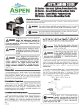
2" MIN.
2" MIN.
2" MIN.
2" MIN.
CAP OR PLUG
Trap must be within 4'
of furnace / air handler
condensate drain connection.
Close as possible
3. Swedge using approved industry practices, or use
eld supplied coupler, on indoor unit coil connections.
Connect eld supplied refrigerant tubing to coil
connections.
4. Flow a small amount of nitrogen through the tubing
while brazing.
5. Use good brazing technique to make leakproof joints.
6. Minimize the use of sharp 90 degree bends.
7. Insulate the suction line and its ttings.
8. Do NOT allow un-insulated lines to come into contact
with each other.
F. LEAK CHECK
1. Using a manifold gauge, connect an external supply
of dry nitrogen to the gauge port on the liquid line.
2. Pressurize the connecting lines and indoor coil to
150 PSIG maximum.
3. Leak check brazed line connections using soap
bubbles. Repair leaks (if any) after relieving pressure.
4. Evacuate and charge the system per the instructions
packaged with the outdoor unit.
G. CONDENSATE DRAIN PIPING
(SEE FIGURE 3)
NOTE:
When coils are installed above ceilings or in other
locations where damage from condensate overow
may occur, a eld fabricated auxiliary drain pan
shall be installed under the coil enclosure. Drain
lines from this pan must be installed, but should
NOT be connected to the primary pan. These drain
lines should terminate in an area easily seen by the
homeowner, but not located to drip on sidewalks or
other slip hazard areas.
FIELD FABRICATED TRAP
There is only a holding charge of dry air in the indoor coil,
therefore no loss of operating refrigerant charge occurs
when the sealing plugs are removed.
1. Remove sealing plugs and use pipe cutter to remove
spun closed ends.
2. Field supplied tubing should be cut square, round
and free of burrs at the connecting end. Clean the
tubing to prevent contaminants from entering the
system.
18-AD40D1-1C-EN 5
Installers Guide
CAUTION
!
TXV sensing bulb is sensitive to heat. Do not
assemble to suction/vapor line until after eld
brazing is complete and line is cool to touch.
I. TXV BULB HORIZONTAL MOUNTING
The orientation and location of the TXV bulb has a major
inuence on the system performance.
It is recommended that the TXV bulb be installed parallel
to the ground (on a horizontal plane). The bulb position
should be at 2 o-clock or 10 o-clock. See Figure 4 for
recommended position of TXV bulb in the horizontal
plane.
J. TXV BULB VERTICAL MOUNTING
While it is recommended that the TXV sensing bulb
is mounted in the horizontal plane, some installation
congurations may require that the sensing bulb be
mounted vertically. In this instance, place the bulb such
that the capillary tubes are directed upwards as shown in
Figure 5.
The TXV sensing bulb should be mounted away from any
bends on a clean smooth section of suction/vapor line,
using the metal clamp provided. In order to obtain a good
temperature reading and correct superheat control, the
TXV sensing bulb must conform to the following criteria:
1. The sensing bulb must be in direct and continuous
contact with the suction line.
2. The sensing bulb should be mounted horizontally on
the suction line.
3. The sensing bulb should be mounted at the 2 o'clock
or 10 o'clock position on the circumference of the
suction line.
4. The sensing bulb must be insulated from outside air.
A properly mounted sensing bulb will prevent false
readings caused by liquid refrigerant that may have
formed inside the suction/vapor line. Insulation will
protect the sensing bulb from false readings due to
contact with warm air.
SENSING BULB
SUCTION LINE
Bulb position at
2 o’clock or
10 o’ clock
Refrigerant &
Oil Flow
Direct Capillary
Tube Upwards
Metal
Strap
Sensing Bulb location
on pipe wall opposite
to that being hit by
refrigerant and
oil leaving the
distributor tubes
Suction
Line
RECOMMENDED LOCATION FOR
VERTICAL TXV BULB MOUNT
RECOMMENDED LOCATION FOR
HORIZONTAL TXV BULB MOUNT
6 18-AD40D1-1C-EN
Installers Guide
Is sub cooling at the
outdoor unit between
8 to 12F?
NO
YES Is superheat
< 5F?YES
Correct air
flow
problem
Is air flow at least
350 CFM per ton?
YES
NO
Remove sensing bulb from the
suction line. Measure superheat
at indoor coil while holding the
bulb in bare hand for one minute.
Does superheat decrease?
Measure superheat at indoor coil
while placing the bulb in an ice
and water bath for one minute.
Does superheat increase?
YES
Replace the
TXV
NO
TXV is OK
NO
Is superheat
< 20F?
NO
YES
NO
Is indoor
temperature more
than 85F?
NO
Is sub cooling less
than 8F?
YES
Confirm that charge
is correct and look
for dirty or restricted
outdoor coil.
Confirm that
charge is
correct.
NO
Before starting, insure the
blower wheel, indoor and outdoor
coils are clean.
Is the liquid line
temperature at indoor
coil within 8F of outdoor
liquid line temperature?
YES
Verify line set is
sized properly
for application
NO
The system is running at max
capacity and this may be
causing the High superheat.
Wait until indoor temperature
is less than 80F and check
superheat again.
YES
YES
Verify inlet screen
of inlet tube
assembly is clear
of debris
NO Has TXV screen
been checked and
cleaned?
YES
Inlet screen located in liquid line. Check, clean, &
replace if necessary.
18-AD40D1-1C-EN 7
Installers Guide
Wrap TXV with wet cloth before
brazing. Direct torch away from
wrapped valve.
About Trane and American Standard Heating and Air Conditioning
Trane and American Standard create comfortable, energy efficient indoor environments for residential applications.
For more information, please visit www.trane.com or www.americanstandardair.com
The manufacturer has a policy of continuous data improvement and it reserves the right to change design and specifications without notice. We
are committed to using environmentally conscious print practices.
© 2022
18-AD40D1-1C-EN 31 Mar 2022
Supersedes 18-AD40D1-1B-EN (January 2022)
  • Page 1 1
  • Page 2 2
  • Page 3 3
  • Page 4 4
  • Page 5 5
  • Page 6 6
  • Page 7 7
  • Page 8 8

Trane 4PXFH004BC3HHA Installation guide

Category
Split-system air conditioners
Type
Installation guide

The Trane 4PXFH004BC3HHA is a horizontal, flat "cased" coil designed for use as cooling only or in combination with a heat pump outdoor section. It features a durable construction with copper/aluminum coils, a compact design for easy installation, and a variety of features to enhance performance and efficiency. With its ability to provide reliable cooling and its compatibility with various systems, this coil is an excellent choice for a wide range of residential and commercial applications.

Ask a question and I''ll find the answer in the document

Finding information in a document is now easier with AI