Page is loading ...

1

2
FACTORY CONTACT INFORMATION
BAY TEK GAMES INC.
Pulaski Industrial Park
1077 East. Glenbrook Drive
Pulaski, WI 54162 USA
PARTS
P: 920.822.3951 X 1101
F: 920.822.1496
E: parts@baytekgames.com
MON - FRI
8 AM - 5 PM C.S.T.
SERVICE
P: 920.822.3951 X 1102
F: 920.822.1496
E: service@baytekgames.com
SALES
P: 920.822.3951
F: 920.822.8936
E: sales@baytekgames.com
All games are proudly manufactured at our factory in Pulaski, Wisconsin, USA
GAME INSPECTION
Inspect the game for any damaged, loose, or missing parts. If damage is found, please
contact your freight carrier rst. Then, contact Bay Tek Games’ Service Department at
920.822.3951 or e-mail them at [email protected] for further assistance.
JOIN OUR SERVICE FIRST NETWORK!
This free service is intended to keep you up to date on the latest
game information, early notication of parts specials, pertinent
technical bulletins, updates on retro t parts, software upgrades,
and much more.
Log on to: www.baytekgames.com/parts
then click on the Parts N’ Service tab, or scan the QR code to
the right with your Smartphone to jump straight to this game’s
parts page!
Scan here!

3
TABLE OF CONTENTS
FACTORY CONTACT INFORMATION ..............................2
WELCOME TO: Grand FUN-alley ..................................4
HOW TO PLAY ................................................5
SPECIFICATIONS ..............................................6
SOFTWARE VERSION ..........................................6
SAFETY PRECAUTIONS ........................................6
DIP SWITCH SETTINGS ........................................7
QUICK SET UP GUIDE ........................................8-9
MAIN MENU FUNCTIONS ......................................10
GAME SETUP MENU ..........................................11
TICKET PATTERNS ...........................................12
DIAGNOSTICS MENU .........................................13
STATISTICS MENU ............................................13
TROUBLESHOOTING GUIDE ................................14-21
UPDATING SOFTWARE ........................................22
WIRING DIAGRAMS ........................................23-28
PARTS LIST .................................................29
PARTS PICTURES .........................................30-32
DECAL IDENTIFICATION .......................................33
MAINTENANCE LOG ..........................................34
TECHNICAL SUPPORT ........................................35
WARRANTY .................................................36

4
WELCOME TO: Grand FUN-alley!
Congratulations on your Grand FUN-alley purchase!
This revolutionary alley bowler will pump up the excitement in your game room with its
fun graphics and sounds, and the ablitlty for up to four players to compete against each
other! The 22” at screen monitor provides a friendly user interface complete with ador-
able characters and two different game play options!
Please take a moment to read through this manual and be sure to contact our factory if
you have any questions, or would like some more information.
Thank you for your purchase! Your business is important to us and we hope you enjoy
this game as much as we do!
Your Friends at Bay Tek Games
GAME INSPECTION
Inspect the game for any damaged, loose, or missing parts.
If damage is found, please contact your freight carrier rst.
Then, contact Bay Tek Games’ Service Department at 920.822.3951
or e-mail them at [email protected] for further assistance.

5
HOW TO PLAY
Step right up and pick your game! Classic
Roller or Ring of Fire, 1-4 players.
Roll all nine balls into the targets, according
to the directions displayed on the monitor.
See frame-by-frame scores and compare with
the other players! In Ring-of-Fire, aim for the
lighted ring for Double Points!
Grab your tickets and play again!

6
GAME SPECIFICATIONS
SAFETY PRECAUTIONS
WEIGHT
NET WEIGHT 450 LBS.
SHIP WEIGHT 550 LBS.
DIMENSIONS
WIDTH 30”
DEPTH 114”
HEIGHT 80”
OPERATING TEMPERATURE
FAHRENHEIT 80-100
CELSIUS 26.7-37.8
POWER REQUIREMENTS
INPUT VOLTAGE
RANGE
100 to 120
VAC /220 to 240
VAC
INPUT FREQUENCY
RANGE 50 HZ / 60 HZ
MAX START UP
CURRENT
OPERATING
CURRENT
2.6 AMPS @ 115 VAC 1.5 AMPS @ 115 VAC
1.3 AMPS @ 230 VAC .75 AMPS @ 230 VAC
DANGER
DO NOT perform repairs or maintenance on this game with the power ON.
Unplug the unit from the wall outlet or shut off the power strip located inside the cabinet.
!!
NOTICE
Modications to the mechanical, electrical and structural components of this game
may void its compliance certications.
!!
WARNING
Use of ammable subtances can cause sever burns or serious injury.
Always use NON-FLAMMABLE solvents for cleaning. DO NOT use gasoline kerosene or thinners.
!!
CAUTION
Lifting heavy objects can cause back, neck or other injuries. Be sure adequate lifting and moving
devices are available when unloading, unpacking and moving this game.
!!
ATTENTION
Be sure the electrical power matches the game requirements. See the serial number located on the
back of the game cabinet. Always plug into a grounded circuit. If the supply cord is damaged, it must
be replaced by an approved cord or assembly provided by the manufacturer.
!!
IN CASE OF EMERGENCY
UNPLUG THE POWER CORD.
The power cord must be accessible at all times in case of an emergency.
!!

7
DIP SWITCH SETTINGS
The dip switch bank is located on the mainboard,
inside the front door of the game.
*factory default settings are highlighted below
SWITCH 1 2 3 4
ON
OFF
THE DIPS MUST BE SET AS SHOWN FOR THE GAME TO FUNCTION PROPERLY

8
QUICK SET UP GUIDE
Place the target cabinet near its nal location.
Push the ramp cabinet to about a foot from
the target cabinet, and plug in the six sets of
cables as shown. The phone cable linkage can
be found in the cashbox of the game.
Slide the ramp cabinet ush to the target cabi-
net.
from the front
from behind

9
QUICK SET UP GUIDE
Drop the 9 balls (found in a box inside the
target cabinet) into the playeld.
Plug the power cable into the back of the
target cabinet and into a standard 110V elec-
trical outlet.
Open the front doors of the ramp and switch
the power strip to “on”.
Congratulations! You’re Ready to Roll!

10
MAIN MENU FUNCTIONS
The menu access buttons are located inside the front
door of the ramp.
Press the MENU/SELECT button to enter the
Main Menu.
Move through the menu with the SCROLL
button.
Make your selection with the MENU/SELECT
button.
CLEAR CREDITS
Press and hold the MENU/SELECT button while “CLEAR CREDITS” is highlighted until
“CREDITS CLEARED” appears to the right.

11
GAME SETUP MENU
Credits/
Game 012345678
Ticket
Pattern
(see next page)
1 2 3 4 5 6 7 8 9 10 11 12 13
14 15 16 17 18 19 20 21 22 23 24 25
Fixed Ticket
Payout DISABLED 1 TICKET TO 40 TICKETS
Attract
Volume 0 10 20 30 40 50 60 70 80 90 100 110 120
Game
Volume 0 10 20 30 40 50 60 70 80 90 100 110 120

12
TICKET PATTERNS
TICKET
PATTERN
GAME SCORE (in thousands)
0
-
9
10
-
14
15
-
19
20
-
24
25
-
29
30
-
34
35
-
39
40
-
44
45
-
49
50
-
59
60
-
69
70
-
79
80
-
89
90
+
TICKETS
11 2 3 4 5 6 7 8 9 10 11 12 13 14
21 2 3 4 5 6 7 8 9 10 25 50 75 100
31 2 3 4 5 6 7 10 15 25 50 100 150 1000
41 3 5 7 9 11 13 15 17 20 25 50 75 100
52 4 6 8 10 12 14 16 18 20 30 40 50 100
62 4 6 8 10 12 14 16 18 25 50 75 100 1000
73 4 5 6 7 8 10 15 20 30 50 100 250 1000
84 5 6 7 8 9 10 15 20 25 35 50 100 1000
96 8 10 12 14 16 20 30 40 60 100 200 500 1000
10 4 8 12 16 20 24 28 32 36 40 60 80 100 200
11 4 8 10 12 14 18 20 25 30 35 50 75 100 1000
12 6 8 12 16 20 22 24 26 30 35 50 100 120 1000
13 6 8 10 12 14 16 20 30 40 60 100 200 500 1000
14 8 10 12 14 18 22 30 35 40 50 60 70 80 100
15 8 10 12 14 16 18 20 22 24 26 28 30 50 250
16 8 16 20 24 28 36 40 50 60 70 100 150 200 1000
17 12 16 24 32 40 44 48 52 60 70 100 200 240 2000
18 0 0 1 1 1 2 2 3 4 6 10 20 30 50
19 0 1 1 2 2 2 3 3 3 4 5 10 20 50
20 1 1 2 2 3 3 4 4 5 6 7 8 9 500
21 1 1 2 3 4 5 6 7 8 9 10 15 23 25
22 1 2 3 4 5 6 7 8 9 10 15 20 25 50
23 2 3 4 5 6 7 8 9 10 11 12 15 20 1000
24 2 3 4 5 6 8 10 12 14 16 18 20 25 30
25 3 4 5 6 7 8 9 10 12 14 16 20 25 30

13
DIAGNOSTICS MENU
STATS MENU
This diagnostic mode will help in determining if all sensors and inputs are functioning correctly.
Activating any input listed here should turn the display from OFF to ON.
The game will automatically alternate lighting the targets in numerical order while diagnostic
mode is on.

14
TROUBLESHOOTING GUIDE
Problem Probable Cause Remedy
No power to the
game.
Unplugged.
Connector loose
between head and ramp
Power strip turned off, or
plugs unplugged.
Circuit breaker tripped.
Bad power supply.
Check wall outlet to line filter in back of game.
(A5FI9010)
Check connection between head
and ramp.
Check rocker switch on power strip. Ensure
power cords are pushed up into power strip securely.
Reset power strip breaker switch or building
circuit breaker. Attempt to determine cause.
Refer to Monitor/Motherboard Power Supply Diagnostics
Bill Acceptor on,
but everything
else off.
(Power Supply
not ON)
Power supply unplugged.
Rocker Switch on power
supply is Off.
Power supply shutting
down because of 12 V
overload.
Faulty power supply.
Insure unit is plugged into power strip.
Make sure rocker switch is set ON.
See power supply diagnostics to isolate bad component.
A bad motor or 12 volt short would cause this.
Refer to Monitor/Motherboard Power Supply Diagnostics
section.
Chase lights on
ramp do not flash.
LED strip faulty
Faulty Cable
Faulty Main Board
Unplug one strip from main board and see if both strips
are bad or just one. Remove
plastic cover and examine LED strip.
Check cables from LED strips to main board.
(AACL2100)
Replace main board. (AANEWGEN-PJ)
LED cabinet light-
ing not working.
LED’s to light up playfield
plug into power sup-
ply behind monitor.
Check for proper connection from power supply to power
supply. Check continuity. (AACE2033, AACE2032,
A5PS1008)
Refer to AC Power & 12 Volt Power Wiring
section.
LED’s lighting up
playfield rings not
working.
LED’s in rings will light up
when hole is scored.
Faulty wire or connection.
Faulty LED light strip.
Faulty main board.
Ensure hole is scoring, if not - refer to Game Scores
Wrong Section.
Check for proper connection from LED’s to main
board. Check continuity. Check for damaged connector
between head and ramp game pieces. Refer to Count-
ers,
Rack Sensor and LED’s Wiring section.
(AACE2041, AACE2042, AACE2036, AACE2035)
Replace LED light strip. (AACE2041 or AACE2042)
Replace main board. (AANEWGEN1-PJ)

15
TROUBLESHOOTING GUIDE
Problem Probable Cause Remedy
Dollar Bill
Acceptor not
functioning.
Ensure bill acceptor has 110
Volts AC.
Note: Game will allow 12 Volt
DBA to be installed.
Dirt or debris in acceptor slot.
Ensure acceptor dipswitch is set
to “always enable”
Pinched, broken, or discon-
nected wiring.
Check coin switch for function.
Bill acceptor problem.
Acceptor should cycle stacker at game power up.
If not, check cable connections to power strip.
Caution – 110 Volts AC
Clean with bill reader cleaning card. (A5CC9000)
There are dips on side of acceptor. Set to “always
enable” (not harness enable)
Check wiring from bill acceptor to main board. Re-
pair or replace wiring harness.
(AACE2012)
If coin switch does not work—refer to “Game does
not coin up” troubleshooting.
Refer to troubleshooting section of dollar bill ac-
ceptor manual included with this game or the
diagnostics label of the back of the unit.
Low tickets
displays on
monitor.
Stack of tickets not resting
properly on either of the low
ticket switches
Faulty switch.
Faulty wire or connection.
Faulty main board.
Adjust stack of tickets so they hold both the switch
actuators down.
Replace low ticket switch. (AASW200)
Check for proper connection from switch to main
board. Check continuity. (AACE2025)
Replace main board. (AANEWGEN1-PJ)
No Audio
Volume too
low.
Loose wire.
Faulty
motherboard
Faulty main
Board
Increase the volume by pressing Menu button,
scroll to “Game Volume” and adjust.
Check audio cable connections
from motherboard to main board to speakers.
Check audio cable connections from speaker(AACE8811), cable(AACE206),
main circuit board(AANEWGEN1-PJ), cable(A5CEAU010), motherboard
(AAMB7)
Replace Motherboard. (AAMB7) Motherboard creates sound. Cable can be
removed from motherboard to MP3 player to test for sound amplification. If the
MP3 player works, then motherboard is faulty.
Replace Main Board. (AANEWGEN1-PJ) Main board amplifies sound from
motherboard.

16
TROUBLESHOOTING GUIDE
Tickets do not
dispense.
Ticket tray empty due to faulty
low ticket switch or broken/
loose wires. Switch stuck or
switch wire bent out of position.
Faulty cable to dispenser.
Dirty opto-sensor or paper
dust buildup in ticket dispenser
Notch on tickets too shallow.
Ticket dispenser faulty.
Main circuit board malfunction.
Fill ticket tray. Replace low ticket switch(AASW200).
Repair wiring. Clean ticket tray of dirt, loose tickets or
debris. Bend switch wire to correct position under tickets.
Check wiring continuity from dispenser to main board
(AACE2025) Check for pinched, broken or disconnected
wires. Replace as necessary.
Clean with compressed air and if necessary wipe
sensor with isopropyl alcohol on a cotton swab.
Flip tickets and load upside-down to have large cut
notch toward opto sensor.
Replace dispenser with spare working dispenser
(A5TD1)
Replace main board if possible to isolate the problem to
the main circuit board. (AANEWGEN1-PJ)
PROBLEM PROBABLE CAUSE REMEDY
Wrong
number
of tickets
dispensed.
Ticket Pattern set wrong.
Dirty opto-sensor on ticket dis-
penser.
Many tickets in memory. If
ticket meter is counting the
tickets coming out, then reset
game.
Notch on tickets cut too
shallow.
Faulty ticket dispenser.
Main circuit board malfunction.
Enter menu and cycle to
Setup Menu.
Verify correct settings for
Ticket Pattern
Clean with compressed air or wipe with isopropyl
alcohol on a cotton swab.
Turn game off, wait 10 seconds, and turn game back
on.
Flip tickets and load upside-down to have large cut notch
toward opto sensor.
Replace with spare working dispenser (A5TD1).
Swap cable from one output on main board to the other
to verify cable/dispenser problem or faulty main board.
(AANEWGEN1-PJ)
Menu buttons
do not work.
Stuck pushbutton.
Cable problem.
Faulty pushbutton.
Inspect pushbutton to make sure it is not stuck.
Check continuity on connector.
Check cable from pushbutton to main board. (AAPB2700
& AACE2018)
Replace pushbutton. (AAPB2700)

17
TROUBLESHOOTING GUIDE
Balls are not
released.
Ball release solenoid sticking.
AC Driver Board defective.
Check for free movement of assembly.
Check for 110 VAC pulse at solenoid.
Check for green LED pulse on driver board
If pulse ok:
Replace fuse located in small box on
AC driver board. (A5FUSE3)
Replace AC Driver board. (AABD5029)
If no pulse, check wires from AC driver to
main board.
Replace main board. (AANEWGEN1-PJ)
Too many balls
are released.
Sensor at ball release blocked,
dirty, or faulty.
Pinched, broken, or discon-
nected wiring.
Clean sensor. Green LED should only come
on when blocked. Replace if needed.
(AACB2203)
Check connections from sensor board to
main board. Check continuity on wires.
Not enough balls
are released.
Game is waiting
for player to throw
balls and there are
none left in track.
Ball count opto
sensor is
defective.
Opto sensor at ball release is
defective.
If this sensor misses a ball, the game will
continue waiting until game time-outs.
Replace sensor. (AACB2203)
If this sensor “sees” 2 balls instead of one.
Replace sensor. (AACB2203)
Meters do not
work.
Game counter
clicks at start of
each game.
Ticket counter
clicks as tickets
come out of
game.
The 2 wires crimped
together may be faulty
Pinched, broken, or discon-
nected wiring
Main board faulty
Inspect crimp to ensure good connection.
Check connections from counters to main
board. Check continuity on wires.
(AACO1000, AACE2035)
Replace main board
Monitor problems
Blurry Monitor
Too bright, or
dim.
Remove marquee in front of monitor.
Press the far left button—black bar will appear on display.
Press the far left button again to select Auto Adjustment.
This may take a few seconds.
Verify that the screen looks good and image is centered.
Problem Probable Cause Remedy

18
TROUBLESHOOTING GUIDE
Problem Probable Cause Remedy
Game scores
wrong.
Game starts with a score
already on display or scores
double points.
Opto is defective under score hole.
Enter menu, go to Diagnostics Menu to check
sensors.
Replace defective opto. (AACB2203)
Game does not
coin up.
Game has audio
track "clinking”
sound from speak-
ers when coin
switch triggered.
If “Power” is not solid ON
Ensure AACE2022 cable is plugged
into blue “IN” socket on main
board. (J16)
Replace if needed.
Replace Serial Interface board.
(AACB2204)
Replace main board.
(AANEWGEN1-PJ)
If “TX” & “RX” are not blinking very fast
Communication to Motherboard faulty.
(Motherboard is located behind monitor.)
Check AACE2011 cable from Serial Interface
board to coupler between head and ramp
(A5CO2002) up to motherboard behind
monitor. Check adaptor (A5CN1031)
Refer to: Monitor/Motherboard Power Supply
Diagnostics
Game does not
coin up.
Game does not
have audio track
"clinking” sound
from speakers
when coin switch
triggered.
One or both coin switches faulty.
Pinched, broken, or
disconnected wiring.
Faulty Main Board
If one is held “closed” - the other will not work
Check connections from coin switches to “Coin”
connector on main board. Check continuity
on wires.
(AACBL4A-DOOR & AACE2004)
Replace main board. (AANEWGEN1-PJ)
Main Board and wiring to coin switch OK.
Check green LED’s on Serial Interface board.
“Power” solid ON
“TX” & “RX” blinking very fast.

19
TROUBLESHOOTING GUIDE
Problem Probable Cause Remedy
Monitor
not work-
ing.
Power
down, wait
10 seconds
and power
up again.
Monitor says
NO SIGNAL
for 5 seconds
after power
up.
Then dark.
Small 12 Volt power connector unplugged
on motherboard.
Monitor VGA cable unplugged.
Large power connector unplugged on
Motherboard
Faulty or loose RAM
Refer to Monitor/Motherboard Power Supply Diagnostics Section
to check for faulty power supply or motherboard.
Monitor has
nothing at all
on power up.
Power cable unplugged from
monitor.
Faulty monitor.
Ensure power is plugged into back of
monitor, down to power strip.
Replace monitor. (A5MO2200)
Error on
screen at
power up.
Re-Boot
game to see
if problem
still exists.
Display stops at "No bootable
device -- insert boot disk and
press any key"
Display shows “Puppy Video
Wizard” or “Xorg”
Flashdrive unplugged from board or
faulty. Re-seat and try power on to
game again.
Replace USB software stick.
Game is not recognizing monitor.
Ensure VGA cable is secure to I/O
board.
Connect keyboard to motherboard
and press enter and enter again on
default settings.
Lights under Red & Blue
Gameplay Pushbutton do
not come on.
Burnt out LED bulb.
Faulty Cable
Faulty Main Board
Replace switch/bulb assy(A5PB2001, A5PB2002)
Check cables from pushbutton to main board.
(AACE2030, AACE2003, AACE2035)
Refer to Board Communication, Player Change
Buttons Wiring Diagram
Replace main board. (AANEWGEN-PJ)
Lights under Red & Blue
Gameplay Pushbutton
stays on.
Surface mounted
transistor blown on
main board.
Replace main board. (AANEWGEN-PJ)
Red & Blue Gameplay
Pushbuttons do not work.
Pushbutton itself is
broken or stuck down
Faulty Cable
Faulty Main Board
Clean switch and ensure it moves freely.
Replace if needed. (A5PB2001, A5PB2002)
Check cables from pushbutton to main board.
(AACE2030, AACE2003, AACE235)
Refer to Board Communication, Player Change
Buttons Wiring Diagram
Replace main board. (AANEWGEN-PJ)

20
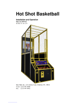
DOLLAR BILL ACCEPTOR DIAGNOSTICS
FLASHING
CODE DESCRIPTION CORRECTIVE
ACTION
LEDs off Power off Turn on power
LEDs on Acceptor is OK
1 flash Bill path blockage Un-jam bill path
2 flashes Stacker jam Un-jam stacker
3 flashes Cassette is full of bills Empty the cassette
4 flashes Cassette is removed Replace the cassette
5 flashes Acceptor is defective Replace the acceptor
6 flashes Acceptor not enabled See service manual
10 flashes Configuration Mode Power down to exit
Rapid flashing
during operation
Stringing attempt de-
tected; or sensors dirty Clean the sensors
To enter Diagnostic Mode, press and hold the
Diagnostic Button on the back left corner of the DBA for
1-3 seconds.
The lights above the bill slot will flash the code.
First determine if Bill Acceptor has power:
Turn game ON—The bill acceptor should make noise as stacker cycles and
green lights on outside bezel should flash.
If NO power:
Due to the different models and brands of Bill Acceptors that are used:
Examine Bill Acceptor and determine if acceptor is 12 Volt DC or 110 VAC
Use meter to measure voltage at cable going into Bill Acceptor.
If power is OK:
Clean Bill Acceptor path to make sure there is nothing jamming unit.
Enter DBA Diagnostics Mode -
Important—Do not hold button down too long or Bill Acceptor will enter
programming mode.
If accidentally entered programming mode by mistake—Unplug game and plug back in.
ERROR CODES
Count the number of flashes on front bezel of Bill Acceptor and
follow chart for repair.
Note: There are many different models and brands of Bill Acceptors that are used on
redemption games. Your Bill Acceptor may differ from the unit shown.
/