Page is loading ...

Owner’s Manual
Trouper
™
and Stagehand
™
Platform Systems
TROUPER PLATFORM
SYSTEMS
Safety Precautions . . . . . . . . . . . . . . . . . . . . . . . . . . . . . . . . . . 3
Warranty . . . . . . . . . . . . . . . . . . . . . . . . . . . . . . . . . . . . . . . . . . 4
Introduction. . . . . . . . . . . . . . . . . . . . . . . . . . . . . . . . . . . . . . . . 5
Unpacking or Setting Up for the First Time . . . . . . . . . . . . . . . 5
Setting Up Individual Platform Units. . . . . . . . . . . . . . . . . . . . . 6
Same-Height Platform Systems
Connecting Same-Height Platforms . . . . . . . . . . . . . . . . . . . . 8
Installing Guard Rails . . . . . . . . . . . . . . . . . . . . . . . . . . . . . . . 9
Installing Drapery Enclosures. . . . . . . . . . . . . . . . . . . . . . . . 10
Installing the Stairway(s). . . . . . . . . . . . . . . . . . . . . . . . . . . . 11
Installing a Backdrop . . . . . . . . . . . . . . . . . . . . . . . . . . . . . . 12
Riser Platform Systems
Typical Riser Layouts . . . . . . . . . . . . . . . . . . . . . . . . . . . . . . 13
Connecting Riser Sections . . . . . . . . . . . . . . . . . . . . . . . . . . 14
Installing Chair Stops . . . . . . . . . . . . . . . . . . . . . . . . . . . . . . 17
Installing Closure Panels . . . . . . . . . . . . . . . . . . . . . . . . . . . 17
Installing Guard Rails . . . . . . . . . . . . . . . . . . . . . . . . . . . . . . 19
Disassembling the Platform System. . . . . . . . . . . . . . . . . . . . 20
Loading the Storage Carts . . . . . . . . . . . . . . . . . . . . . . . . . . . 21
Maintenance . . . . . . . . . . . . . . . . . . . . . . . . . . . . . . . . . . . . . . 22
Replacement Parts List . . . . . . . . . . . . . . . . . . . . . . . . . . . . . 22
Safety Precautions . . . . . . . . . . . . . . . . . . . . . . . . . . . . . . . . . 33
Warranty . . . . . . . . . . . . . . . . . . . . . . . . . . . . . . . . . . . . . . . . . 34
Introduction. . . . . . . . . . . . . . . . . . . . . . . . . . . . . . . . . . . . . . . 35
Unpacking or Setting Up for the First Time . . . . . . . . . . . . . . 35
Setting Up Individual Platform Units. . . . . . . . . . . . . . . . . . . . 36
Connecting Same-Height Platforms . . . . . . . . . . . . . . . . . . . . 37
Installing Guard Rails . . . . . . . . . . . . . . . . . . . . . . . . . . . . . . . 38
Installing Drapery Enclosures. . . . . . . . . . . . . . . . . . . . . . . . . 39
Installing the Stairway(s). . . . . . . . . . . . . . . . . . . . . . . . . . . . . 40
Installing a Backdrop . . . . . . . . . . . . . . . . . . . . . . . . . . . . . . . 41
Disassembling the Platform System. . . . . . . . . . . . . . . . . . . . 42
Transporting and Storing Platform Units. . . . . . . . . . . . . . . . . 43
Maintenance . . . . . . . . . . . . . . . . . . . . . . . . . . . . . . . . . . . . . . 44
Replacement Parts List . . . . . . . . . . . . . . . . . . . . . . . . . . . . . 44
This publication includes complete Owner’s Manuals for both the Trouper and Stagehand Platform
Systems.
Please take a few minutes to read the appropriate sections and to familiarize yourself with Trouper
or Stagehand’s operating features. If you should need additional information, just write or call.
STAGEHAND PLATFORM
SYSTEMS
©Wenger Corporation 2005 Printed in USA 09/05 Part #176A700-5
Wenger Corporation, 555 Park Drive, P.O. Box 448, Owatonna, Minnesota 55060-0448
Questions? Call.....USA: (800) 733-0393 • International (call collect): (507) 455-4100 • www.wengercorp.com

2
Trouper Platform Systems

3
SAFETY PRECAUTIONS
SETUP
Insist that anyone who assists with the set up of
the Trouper Platform System be familiar with
this manual.
GUARD RAILS
The guard rails are indicators of the perimeter of
the platform system, and are not intended as a
universal restraint. Excess weight or pressure
will cause them to collapse.
Never use the rails:
• As a crowd barrier
• As a perch
• As a tie-down.
PLATFORM STABILITY
All platform units must be locked together using
the unit-to-unit clamps beneath the stage
surface. These clamps are designed for use
only with one-level stage sets. Do not set up a
multilevel stage using Trouper units unless
adequate special clamping is provided to secure
the levels together. See “Connecting Riser
Sections” on page 14.
Trouper platforms are designed for level
surfaces only and contain no provision for
adjusting leg heights.
TRANSPORT/STORAGE CARTS
Never stack more than three platforms on a
3-Unit Cart, six platforms on an 6-Unit Cart,
eight platforms on an 8-Unit Cart, or twelve
platforms on a 12-Unit Cart.
Before moving or storing platforms on 6- or 8-
Unit Carts, always secure the units using the
unit lock assembly at the top of the cart. On a
12-Unit Cart, secure the units by slipping them
into the guides on the upright handle assembly.
See “Loading the Storage Carts” on page 21 for
more information.
Throughout this manual, you will find CAUTIONS and WARNINGS:
•WARNING means that if safety information is not followed someone could be seriously
injured or killed.
•CAUTION means that if safety information is not followed the platform could be damaged or
personal injury could result.
!CAUTION
To avoid injury,
some setup steps
may require two
workers.
!WARNING
Rails may collapse
if excess weight or
pressure applied.
!WARNING
Platforms can fall
unless stacked and
secured properly
on the cart.
!WARNING
Platforms are
unsafe if unit-to-
unit clamps are not
used as specified.

WARRANTY
Wenger Trouper Platform Systems are guaranteed free of defects in
materials and workmanship for five full years.
Our guarantee assures you of either a full refund or repair or
replacement of the defective materials or workmanship without charge,
at the discretion of our Customer Service Department. Just call a
Customer Service Representative at 1-800-733-0393 and state the
reason you are dissatisfied. If a product return is necessary, your
Representative will issue a return authorization. This is your sole remedy
for breach of this warranty.
Should you have a question or problem with any Wenger product, don’t
hesitate to call, even if the product is past warranty. It’s important to us
that all our customers be satisfied.
This is the sole warranty made by Wenger. Wenger disclaims all other
warranties, including the warranties of merchantability and fitness for a
particular purpose, as well as all liability for incidental, consequential,
special, and indirect damage. Wenger liability for direct damages shall
be limited to the amount you paid for the product involved. Wenger
reserves the right to make product changes without obligation to
incorporate such changes into products previously sold.
Some states do not allow the exclusion or limitation of damages or
warranties, so the above may not apply to you. This warranty gives you
specific legal rights. You may also have other rights which vary from
state to state.
4

5
INTRODUCTION
Trouper platform units are available in four sizes (4' x 8', 3' x 8', 4' x 6', and 3' x 6') and in four fixed
elevations (8", 16", 24", and 32"), as well as two dual-height options (16/24" and 24/32"). Platform
systems can be constructed with units that are all the same height (standard stage), or with units at
different heights (risers, or multi-level stage).
Do not set up a multilevel stage using Trouper units unless adequate special clamping is provided to
secure the levels together. See “Connecting Riser Sections” on page 14.
For efficient moving and storing of the platform units, several sizes of Wenger move-and-store carts are
available. See “Loading the Storage Carts” on page 21 for more information.
Easily attached 39" wide stairway units with double handrails are available in a 2-step version
(for 16" or 24" stage heights) and a 3-step version (for 24" or 32" stage heights).
Guard rail assemblies should be used with all stage elevations, and are available in 3', 4', 6' and 8'
lengths. The top rail on all guard rails is located 42" above the platform surface. The rail assemblies
include a chair stop rail.
To give the stage or risers a more formal, finished look, the following accessories are also
available from Wenger:
• drapery skirting
• drapery backdrops
• front and side closure panels.
UNPACKING OR SETTING UP FOR THE FIRST TIME
1. Remove all parts from their shipping cartons (refer to the packing list enclosed with the shipment).
Save the packaging materials at least until the stage system has been set up the first time.
2. Sort all platform units and accessories by size, leg length, etc.
3. Assemble all carts and stairways that are shipped disassembled - using the instructions supplied
with them.
4. If the stage or risers will be stored before being set up, see “Loading the Storage Carts” on page 21
and “Disassembling the Platform System” on page 20.
If the platform units will be set up immediately, see “Setting Up Individual Platform Units” on page 6.
IMPORTANT: Read this entire manual before starting to set up a platform system.
!WARNING
Platforms are
unsafe if unit-to-
unit clamps are not
used as specified.

SETTING UP INDIVIDUAL PLATFORM UNITS
REMOVING THE PLATFORM UNITS
FROM THE CART
1. Be sure the platform units are secured
to the cart before moving. Position the
cart near the set up area.
2. Open all legs on the outside platform
unit before removing from the cart.
3. Straighten the hinged brace on each
leg. If necessary, push in on the brace
lock until it engages.
4. With a 6 or 8-Unit Cart, release the first
platform unit by pushing the unit lock to
the right.
!CAUTION
To avoid injury, two
people should set
up the platforms.
6

SETTING UP INDIVIDUAL PLATFORM UNITS (CONTINUED)
5. Rotate the platform unit off the cart and set it upright on its legs.
6. Repeat steps 2 - 5 for the remaining platform units.
If all of the platform units being set up are same-height platforms, go to page 8.
If setting up platform units as riser systems or as a multilevel stage, go to page 13.
7

8
TROUPER SAME-HEIGHT PLATFORM SYSTEMS
CONNECTING SAME-HEIGHT PLATFORMS
1. Position the first two platform units at their desired stage location (at the rear center of the stage).
2. Attach them together in at least two places, using the unit-to-unit clamps beneath the platform
surface.
3. Attach the remaining platform units together in the same way.
!WARNING
Platforms are
unsafe if unit-to-
unit clamps are not
used as specified.

9
INSTALLING GUARD RAILS
To attach each guard rail assembly to the platform
system:
1. Unscrew the handle at the bottom of each
upright, just until pulling the handle outward
allows the lower shoe to drop. Don’t unscrew
all the way.
2. Set the guard rail on the platform, with the
lower shoe on each upright positioned below
the deck surface. Center the rail side-to-side
on the platform section.
3. Lift the lower shoe on each upright until the
handle drops.
4. Slide the Rail against the platform deckand
turn the handle until the lower shoe is tight
against the platform deck.

10
INSTALLING DRAPERY ENCLOSURES
Draperies are often used to close off the lower portion of the stage, for better appearance. They can be
attached to the stage even where stairways or back/side rails are used.
The draperies are secured to the stage using plastic clips fitted with a hook tab that connects to a loop
fastener on the drapery.
Drapery enclosures must be attached after guard rails are installed, and before stairways.
To attach the draperies:
1. Install clips along the stage perimeter wherever drapery is desired (about 12" apart).
2. Beginning at a corner of the stage, press the drapery onto the clips.
3. Continue attaching the drapery to the clips until the section is completely installed.
4. Repeat the above procedure with the remaining drapery sections.

11
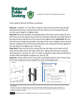
INSTALLING THE STAIRWAY(S)
The 2-step and 3-step stairways supplied with
Trouper Platform Systems can be adapted to
several staging models and heights.
The hook tube assemblies that slip into
guides on each side of the stairway frame
have a notched plate which can be
interchanged to match the framework on the
bottom of the staging. The illustration shows
the appropriate notched plate properly
mounted for use with Trouper Platform
Systems.
Each stairway model can be adjusted for two
platform heights:
• The 2-step stairway can be adjusted for
16" or 24" platform heights
• The 3-step stairway can be adjusted for
24" or 32" platform heights.
When the snap button on the hook tube
assembly is in the matching hole in the guide,
the stairway can be connected to the higher
platform. When the hook tube assembly is all
the way down in the guide, the stairway can
be connected to the lower platform.
The notched plates must be on the outside of
the tubes, extending away from the stairway
frame.
To attach the stairway:
1. Be sure that the stairway has the correct
hook tube assemblies (see above).
2. Adjust the hooks to the proper height for
the stage.
3. Tip the stairway into place.
4. Check that the notch in the hook tube is
secured to the stage framework, and that
the stairway feet are flat on the floor.
5. Tuck the top edge of drapery enclosures
under the lip of the stage at stairway
locations.

12
INSTALLING A BACKDROP
NOTE: Two people are required to install the
backdrop support.
1. Unfold each backdrop support and set it on
a guard rail as shown.
2. Hook-and-loop tape is attached to both
surfaces so that drapery sections can be
secured to the crossbar of the backdrop
support.
Use a ladder to attach the drapery. Wrap
any excess drapery around the end of the
crossbar.
For disassembly instructions, see page 20.

13
TROUPER RISER PLATFORM SYSTEMS
TYPICAL RISER LAYOUTS
Use rectangular and pie-shaped units as shown.
At the third elevation of pie-shaped locations:
-Choral risers have a single unit
-Band risers have two units, one left-hand and one right-hand. If a fourth elevation has been
supplied, both choral and band risers will have two units, one left-hand and one right-hand.

14
CONNECTING RISER SECTIONS
1. Set up the back row of platforms (including
any rear extensions), to verify that there is
enough space for the full riser set. Do not
lock these units together until the
remaining units are positioned.
2. Place interlocking leg spacers on the floor
under the inside legs of the rectangular
units as shown in the illustration. Platform
legs fit into the hole in the center of the
spacer.
Note: Interlocking leg spacers are used
only to connect rectangular platform units
together. Use metal spacer assemblies to
connect pie-shaped platform units together
as decribed on the following page.
3. Attach adjoining units together in at least
two places, using the unit-to-unit clamps
beneath the platform surface.
4. Position the remaining units for the center
section — first the middle elevation (16"),
then the front (8"). Repeat the pattern for
the interlocking leg spacers on the
rectangular units.
5. Assemble the next section (pie-shaped
units) to the left of the completed section,
again starting with the highest elevation
and working down to the lowest elevation.
!WARNING
Platforms are
unsafe if unit-to-
unit clamps are not
used as specified.
Position the remaining
center units next

15
CONNECTING RISER SECTIONS (CONTINUED)
6. Use the riser spacer tool to align the
edges of the pie-shaped units vertically.
Make sure the corners of the decks are
aligned.
7. Connect all matching height units together
using the unit-to-unit clamps.
8. Connect different height pie-shaped units
together using metal spacer assemblies.
9. Assemble the next section ( pie-shaped
units) to the right of the completed
sections, again repeating steps 6 - 8 and
connecting same-height sections with the
unit-to-unit clamps.
9. Continue until all sections are installed.
!WARNING
Always install all leg
spacers, and secure
each section with
unit-to-unit clamps,
before beginning a
new section.

16
CONNECTING RISER SECTIONS (CONTINUED)
INSTALL TRI-CORNER FILLERS (IF USED)
10. Tri-corner fillers are used to fill corner voids in
rectangular configurations. To install them:
a. Unfold the two legs on the side that has
two keepers, until they lock in place.
Partially unfold the third leg (don’t lock
it).
b. Set the tri-corner approximately in place,
and raise the corner with the unfolded leg
until the two keepers will slide under the
edging of the opposite riser. Push the tri-
corner tight against that riser.
Lower the corner until the single keeper
will slide under the edging of the adjacent
riser. Slide the tri-corner until it contacts
the riser.
Raise the corner. Lower and lock the third
leg.
Make sure that all legs are locked in their
open position.
!WARNING
Tri-corner fillers
can easily tip if not
properly secured.

17
INSTALLING CLOSURE PANELS
There are two styles of closure panels:
• Those that go between the different levels
of units (elevation closures). They have
positioning brackets along the top edge.
• Those that touch the floor (along the front
of the bottom row, and the side closure
panels). They have clips along the top
edge to snap the closure onto the unit.
To simplify installation, the closures are
labeled (on the back side) by a letter that
indicates their length and position. See the
illustration.
Note: On some rectangular riser sets, there
may also be various odd-length closure
panels that are not labeled.
It is suggested that you install any 8' and 6'
closures first. This will make it easier to
identify where the smaller closures mount.
INSTALLING CHAIR STOPS
The riser was shipped with enough chair stops
to span the back of all elevations on the risers,
plus the sides of end units that are 16" or
higher.
Chair stops cannot be installed where closure
panels or guard rails are used.
Any excess chair stop may be discarded.
To install chair stops:
1. Snap chair stop clips onto every unit,
where appropriate, at approximately 24"
intervals.
Note: Side closures must be installed after
the clips, but before the chair stops are
installed. See “Installing Closure Panels”
above.
2. Install the chair stops into the clips, with the
grooved side up.

18
INSTALLING CLOSURE PANELS (CONTINUED)
FRONT FLOOR-LEVEL CLOSURES
1. Interlocking leg spacers must be installed
on the front row of platform legs to provide
a backstop for the front floor closure panels.
2. Snap the panels onto the riser unit. Inside
edge should be flush with interlocking leg
spacer for support.
ELEVATION CLOSURES
Install the panels from the middle of the riser
set, and then work your way toward the ends.
This will even out any gaps between the
elevation closures and the side closure panels.
1. Hook the lower clips onto the lower
elevation units at the same intervals as the
positioning brackets that came installed on
the closure panel.
2. Set the closure panel onto the clips, then
push the closure panel down and rotate it
until the positioning brackets catch the
upper elevation unit.
SIDE CLOSURES
Snap the panels onto the sides of the riser set
(in the same way as the front floor-level
closures).
Note: Chair stop clips must be installed before
the side closures; chair stops must be installed
after the side closures. See “Installing Chair
Stops” on page 17.

19
INSTALLING GUARD RAILS
To attach each guard rail assembly to the platform
system:
1. Unscrew the handle at the bottom of each
upright, just until pulling the handle outward
allows the lower shoe to drop. Don’t unscrew
all the way.
2. Set the guard rail on the platform, with the
lower shoe on each upright positioned below
the deck surface. Center the rail side-to-side
on the platform section.
3. Lift the lower shoe on each upright until the
handle drops.
4. Slide the Rail against the platform deckand
turn the handle until the lower shoe is tight
against the platform deck.

20
DISASSEMBLING THE PLATFORM SYSTEM
1. To remove the drapery from a backdrop:
a. “Peel” the drapery away from the crossbar.
b. Fold the drapery carefully to minimize
wrinkling in storage.
An optional carrying case can be purchased
from Wenger to store the drapery.
c. Press the release button on each upright,
and lift the backdrop support from the guard rail.
2. Remove any stairways by lifting the outer end
(lowest step) until the hook tube assembly is
free of the stage.
3. Remove any drapery enclosures by reversing
the installation procedure. See “Installing
Drapery Enclusures” on page 10.
Don’t remove the clips from the drapery
unless they have to be relocated. Keeping
the clips on the drapery prevents lossing
them and eliminates the need to store separately.
If the clips remain attached to the platform
frame they will interfere with storage of the
platform units.
Carefully fold the drapery to minimize wrinkling. Special drapery hangers are available from Wenger.
4. Remove any guard rails by unscrewing the handles. Store the guard rails on the (optional) guard rail
storage cart.
5. Remove all closure panels.
6. Remove all chair stops.
IMPORTANT: Two people are recommended for the following step.
7. Release the unit-to-unit clamps on the underside of adjacent same-height platforms.
See “Connecting Same-Height Platforms” on page 8.
8. Pull the first platform section away from the stage or riser and place near the storage cart.
Tilt the section onto the cart.
9. Return the legs to their shorter position (if extended on dual-height models).
10. To fold the legs:
a. On each leg brace, slide the brace lock away from the deck,
and use the heel of your other hand to unlock the brace.
b. Fold the legs against the deck.
11. Be sure the platform units are positioned securely on
the cart:
a. On 12-Unit Carts, slide the end of the platform units
all the way into the guides on the handle end.
b. On 6- or 8-Unit Carts, secure each platform unit
with the unit lock.
c. On 3-Unit Carts, the platform units rest against the
diagonal brace.
10. Repeat steps 8 through 11 for the remaining sections.
/