Page is loading ...

RINS867
-
2
User Manual


CONTENTS
CHAPTER 1: INTRODUCTION ...........................................................................................4
1.1 THE KEYPAD AND PROXIMITY READERS....................................................................................4
1.1.1 The PCX LCD Keypad (PCX-LCD/UK) ............................................................................4
1.2 THE INTERNAL READER (PCX-PROX/INT) ...............................................................................6
1.3 THE EXTERNAL READER (PCX-PROX/EXT).............................................................................7
CHAPTER 2: ARMING AND DISARMING THE SYSTEM..................................................8
2.1 ARMING / DISARMING VIA THE KEYPAD.....................................................................................8
2.1.1 Arming Arm Modes Via The Keypad ................................................................................8
2.1.2 Disarming Arm Modes Via The Keypad ...........................................................................8
2.1.3 Arming Partitions Via The Keypad ...................................................................................9
2.1.4 Disarming Partitions Via The Keypad...............................................................................9
2.1.5 Arming Partitions with Partitions Already Armed ............................................................10
2.1.6 Disarming After an Alarm via the Keypad.......................................................................11
2.2 ANTI CODE / ENGINEER RESET...............................................................................................12
2.2.1 Engineer Reset ..............................................................................................................12
2.2.2 Anti Code.......................................................................................................................13
2.3 ARMING / DISARMING VIA THE INTERNAL TAG READER............................................................14
2.3.1 Arming Partitions / Arm Modes via the Internal Tag Reader...........................................14
2.3.2 Disarming Partitions / Arm Modes via the Internal Tag Reader ......................................15
2.4 ARMING / DISARMING VIA THE EXTERNAL TAG READER ..........................................................15
2.4.1 Arming Partitions / Arm Modes via the External Tag Reader..........................................15
2.4.2 Disarming Partitions / Arm Modes via the External Tag Reader.....................................16
CHAPTER 3: ADVANCED FUNCTIONS ..........................................................................17
3.1 CHIME FUNCTION...................................................................................................................17
3.2 OMITTING INPUTS...................................................................................................................17
3.2.1 Omitting Open Inputs .....................................................................................................19
3.3 HOLD UP ALARM VIA THE KEYPAD .........................................................................................19
CHAPTER 4: THE MANAGER MENU ..............................................................................21
4.1 ENTERING THE MANAGER MENU ............................................................................................21
4.2 EXITING THE MANAGER MENU................................................................................................21
4.3 SET DATE & TIME ..................................................................................................................22
4.4 OMIT INPUTS .........................................................................................................................22
4.5 CHANGE CODES ....................................................................................................................22
4.5.1 Changing User Codes and Manager Codes...................................................................22
4.6 DELETING A USER CODE ........................................................................................................25
4.7 REVIEW LOGS .......................................................................................................................25
4.7.1 The Panel Log ...............................................................................................................25
4.7.2 The Access Log .............................................................................................................26
4.8 PHONEBOOK .........................................................................................................................27
4.9 WALK TEST...........................................................................................................................27
4.10 BELL TEST ..........................................................................................................................28
4.11 TEST PHC COMMUNICATIONS ..............................................................................................29
4.12 DIAL OUT MENU ..................................................................................................................30
4.13 ALLOW ENGINEER MENU......................................................................................................31
4.14 BLOCK REMOTE ARM...........................................................................................................31
4.15 BLOCK UDL ........................................................................................................................31
4.16 ENTER ANTI-CODE...............................................................................................................31
4.17 EXIT MANAGER MODE..........................................................................................................31
CHAPTER 5: SERVICE INFORMATION ..........................................................................35
CHAPTER 6: CONTACT INFORMATION.........................................................................36

PCX 256 USER MANUAL
Page: 4 RINS867-2
CHAPTER 1: INTRODUCTION
Congratulations on your purchase of a Pyronix PCX alarm system. The PCX is designed and
manufactured to our ISO9001 approved quality system to offer options to suit your needs.
1.1 The Keypad and Proximity Readers
The PCX panel is active for 24 hours a day and the two basic operation modes are DISARMED
mode and ARMED mode.
DISARMED: In this mode all inputs are disarmed, apart from Fire, Hold Up, 24 Hour, Gas, Tamper
and Fault, which are active 24 hours a day. The Tamper state of all End of Line inputs is always
active irrespective of the input type.
ARMED: In this mode all enabled inputs are armed, and if triggered will generate an alarm
condition. If an alarm is triggered, internal and external sounders will operate for a programmed
period or time. Upon expiry of this time period, the system will automatically rearm.
There are 3 types of operating devices for the PCX: The LCD keypad, the internal proximity reader
and the external proximity reader. Also note that the PCX LCD keypad also has an inbuilt prox
reader.
1.1.1 The PCX LCD Keypad (PCX-LCD/UK)
!!
D
C
B
A
PCX 256.v5.e
Time 14:48 c
Tag
,/+.
JKL
POWER LED
This indicates that the reader has power. The power LED will
extinguish after a couple of seconds.
ALARM LED
This indicates that an alarm activation has occurred.
TAMPER LED
This indicates that a tamper has occurred
FAULT LED
This indicates that a fault has occurred, i.e. device fail etc.
!!!!!!!!!!!!!!!!!!!!!!!!!!!!!!!!!!!!!!!!!!!!!!!!!!

PCX 256 USER MANUAL
RINS867-2 Page: 5
DISARMED LED
This will illuminate for a couple of seconds after the system
has been disarmed.
NUMERICAL BUTTONS
Used to enter user codes and program input names
DIRECTION BUTTONS
Used to select options and scroll display.
OPERATIONAL BUTTON 1
Selects items and enters sub menu indicated in master
manager menu.
Used to arm the panel if flexi-arm is enabled.
OPERATIONAL BUTTON 2
Moves forward to the next main menu item, also clears faults.
THE A KEY
Exit Manager Mode (from a main menu item)
THE B KEY
Moves backwards to the previous menu item
THE C KEY
Chime Button and displays additional information in the log
and the diagnostic functions.
THE D KEY
Moves forward to the next option, or toggles between
‘YES/NO’ choices. Enters the manager mode.
The emergency buttons for the PCX system consist of 2 buttons being pressed to activate a Hold
Up. These are the keys ! and &. On default these are disabled to comply to PD6662. If you
wish for these to be enabled please contact your engineer.

PCX 256 USER MANUAL
Page: 6 RINS867-2
1.2 The Internal Reader (PCX- PROX/INT)
Power
Alarm
Tamper
Fault
Unset
Tag
Power
Alarm
Tamper
Fault
Unset
Tag
Power
Alarm
Tamper
Fault
Unset
Tag
Power
Alarm
Tamper
Fault
Unset
Tag
Power
Alarm
Tamper
Fault
Unset
Tag
Power
Alarm
Tamper
Fault
Unset
Tag
Power
Alarm
Tamper
Fault
Unset
Tag
Power
Alarm
Tamper
Fault
Unset
Tag
Power
Alarm
Tamper
Fault
Unset
Tag
Power
Alarm
Tamper
Fault
Unset
Tag
Power
Alarm
Tamper
Fault
Unset
Tag
Power
Alarm
Tamper
Fault
Unset
Tag
Power
Alarm
Tamper
Fault
Unset
Tag
Power
Alarm
Tamper
Fault
Unset
Tag
Power
Alarm
Tamper
Fault
Unset
Tag
Power
Alarm
Tamper
Fault
Unset
Tag
Power
Alarm
Tamper
Fault
Unset
Tag
Power
Alarm
Tamper
Fault
Unset
Tag
Power
Alarm
Tamper
Fault
Unset
Tag
Power
Alarm
Tamper
Fault
Unset
Tag
Power
Alarm
Tamper
Fault
Unset
Tag
Power
Alarm
Tamper
Fault
Unset
Tag
Power
Alarm
Tamper
Fault
Unset
Tag
Power
Alarm
Tamper
Fault
Unset
Tag
Power
Alarm
Tamper
Fault
Unset
Tag
POWER LED
This indicates that the reader has power present.
PowerPowerPowerPowerPowerPowerPowerPowerPowerPowerPowerPowerPowerPowerPowerPowerPowerPowerPowerPowerPowerPowerPowerPowerPower
ALARM LED
This indicates when an alarm activation as occurred.
AlarmAlarmAlarmAlarmAlarmAlarmAlarmAlarmAlarmAlarmAlarmAlarmAlarmAlarmAlarmAlarmAlarmAlarmAlarmAlarmAlarmAlarmAlarmAlarmAlarm
TAMPER LED
This indicates when a tamper has occurred.
TamperTamperTamperTamperTamperTamperTamperTamperTamperTamperTamperTamperTamperTamperTamperTamperTamperTamperTamperTamperTamperTamperTamperTamperTamper
FAULT LED
This indicates when a fault has occurred, i.e. device fail etc.
FaultFaultFaultFaultFaultFaultFaultFaultFaultFaultFaultFaultFaultFaultFaultFaultFaultFaultFaultFaultFaultFaultFaultFaultFault
DISARMED LED
This will illuminate for a couple of seconds after the system
has been disarmed.
UnsetUnsetUnsetUnsetUnsetUnsetUnsetUnsetUnsetUnsetUnsetUnsetUnsetUnsetUnsetUnsetUnsetUnsetUnsetUnsetUnsetUnsetUnsetUnsetUnset

PCX 256 USER MANUAL
RINS867-2 Page: 7
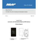
1.3 The External Reader (PCX- PROX/EXT)
POWER LED
This indicates that the reader has been found on the data bus,
and power is present. This will extinguish after a couple of
seconds.
RED LED
This can be programmed to follow an output (For example
you may want the output to illuminate when a partition is
armed). Contact your engineer for more information
The prox tags that are used with the PCX-PROX/INT and PCX-PROX/EXT are shown below:
These can be ordered as a pack of 5 (PCX-PTAG)

PCX 256 USER MANUAL
Page: 8 RINS867-2
CHAPTER 2: ARMING AND DISARMING THE SYSTEM
2.1 Arming / Disarming Via The Keypad
There are a number of ways to arm the PCX 256; either via the keypad, via the keypad proximity
reader, the internal tag reader or the external prox reader. Each involves either entering a valid
user code or presenting a valid tag/card.
2.1.1 Arming Arm Modes Via The Keypad
If the engineer has selected that the system is to be used as a Level arm system rather than a
Partition system, then you will arm the system as follows:
1. Enter your user code (default 1234) or present your card
D
C
B
A
Active Faults
Battery Fault100
Tag
,/+.
JKL
ABC
MNO
DEF
PQRS
GHI
TUV
WXYZ SPACE
2. Before you can arm the system, any active faults will be displayed (see above), press the
key.
3. The system will allow you to arm the required arm mode.
4. Use the numeric and the ¤,¦,§,© keys to select the arm mode you wish to arm and press
the key. The system will start to arm. Once system has armed, a beep will be heard and the
system is armed.
NOTE: The system will only arm depending on what ‘Exit Mode’ is programmed. This would
have been selected by your engineer. For example:
If Timed is selected the system will arm after the exit time has expired.
If Final Door is selected, the system will only arm after the entry/exit door has been opened/closed.
If PTS (Push To Set) is selected, the system will only arm after the Push To Set button has been
pushed.
2.1.2 Disarming Arm Modes Via The Keypad
1. Enter your user code or present
2. The system will be disarmed

PCX 256 USER MANUAL
RINS867-2 Page: 9
2.1.3 Arming Partitions Via The Keypad
If the system is set up as a partition system, the master manager can assign different codes to
individual partitions. Please see Change Codes on page: 22.
1. Enter your user code (default 1234) or present your card
D
C
B
A
Active Faults
Battery Fault100
Tag
,/+.
JKL
ABC
MNO
DEF
PQRS
GHI
TUV
WXYZ SPACE
2. Before you can arm the system, any active faults will be displayed (see above), press the
key.
3. The system will allow you to arm the required arm mode.
4. Use the numeric and the ¤,¦,§,© keys to select the partition(s) you wish to arm and press
the key. The system will start to arm. Once the system has armed, a beep will be heard and
the system is armed.
NOTE: The system will only arm depending on what ‘Exit Mode’ is programmed. This would
have been selected by your engineer. For example:
If Timed is selected the system will arm after the exit time has expired.
If Final Door is selected, the system will only arm after the entry/exit door has been opened/closed.
If PTS (Push To Set) is selected, the system will only arm after the Push To Set button has been
pushed.
2.1.4 Disarming Partitions Via The Keypad
To disarm any partition on the system:
1. If you have only one partition assigned to the card/code, then the partition will be disarmed
automatically (this coincides with the ‘Flexi-Arm’ option – please see page 24). If you have
multiple partitions assigned to a user, then the following will be displayed when you enter your
code or present your card (In this example partitions A and B were armed initially)

PCX 256 USER MANUAL
Page: 10 RINS867-2
D
C
B
A
Arm Partition?
(0123456789 CD)
Tag
,/+.
JKL
ABC
MNO
DEF
PQRS
GHI
TUV
WXYZ
SPACE
2. Press the key. The system will ask which of the armed partitions you wish to disarm:
D
C
B
A
Disarm Partition?
( AB )
Tag
,/+.
JKL
ABC
MNO
DEF
PQRS
GHI
TUV
WXYZ
SPACE
3. Use the numeric and the ¤,¦,§,© keys to select the partition(s) you wish to disarm and
press the key. The system will disarm those partitions.
2.1.5 Arming Partitions with Partitions Already Armed
If for example partitions A and B are already armed, and you would like to arm partitions C and D,
you will do the following:
1. Enter your user code or present your card, the display will show which partitions are available
to arm (partitions A and B are already armed):

PCX 256 USER MANUAL
RINS867-2 Page: 11
D
C
B
A
Arm Partition?
(0123456789 CD)
Tag
,/+.
JKL
ABC
MNO
DEF
PQRS
GHI
TUV
WXYZ
SPACE
2. Press § and ©, and press the key. The system will arm partitions C and D.
2.1.6 Disarming After an Alarm via the Keypad
After an alarm, enter your user code (default 1234). The activated input will be displayed:
D
C
B
A
Alarm Silenced
Input 001
Tag
,/+.
JKL
ABC
MNO
DEF
PQRS
GHI
TUV
WXYZ
SPACE
Press the key to reset the system.
PLEASE NOTE: If engineer restores or anti code restores are enabled you will not be able to
reset the system until a valid engineer code or anti-code has been entered.

PCX 256 USER MANUAL
Page: 12 RINS867-2
2.2 Anti Code / Engineer Reset
The system can be programmed so that it can be only fully reset by an engineer or by an anti-code
reset (ask your engineer to program this feature).
2.2.1 Engineer Reset
After an alarm activation (this example shows a personal attack), enter your user code, the alarm
will silence and the following will be displayed on the keypad:
D
C
B
A
Alarm Silenced
2 Key HU
,/+.
JKL
ABC
MNO
DEF
PQRS
GHI
TUV
WXYZ
SPACE
The display will switch between the activation that has just occurred and ‘Restore Required’.
Press the key. The following display will be displayed:
D
C
B
A
PCX 256.V5.e
Time 02:31 c
,/+.
JKL
ABC
MNO
DEF
PQRS
GHI
TUV
WXYZ
SPACE
The power LED will flash indicating that a restore is required. Enter your engineering code.
“All Faults Have Cleared” will be displayed. Press the key twice, ‘Enter Code’ will be displayed.
Press the key to return to day mode.

PCX 256 USER MANUAL
RINS867-2 Page: 13
2.2.2 Anti Code
After an alarm activation (this example shows a personal attack), enter your user code, the alarm
will silence and the following will be displayed:
D
C
B
A
Alarm Silenced
Restore G12298
,/+.
JKL
ABC
MNO
DEF
PQRS
GHI
TUV
WXYZ
SPACE
The restore number that is shown (for example G12298), will need to be given to your alarm
receiving station, in return they will supply you with a reset code.
Ø Press the key.
Ø Enter the code the ARC have given you. The following will be displayed:
D
C
B
A
Engineer Restore
Performed
,/+.
JKL
ABC
MNO
DEF
PQRS
GHI
TUV
WXYZ
SPACE
‘Enter Your Code’ will be displayed, either enter your user code to arm/disarm the panel, or press
the key to reset to day mode.

PCX 256 USER MANUAL
Page: 14 RINS867-2
2.3 Arming / Disarming Via The Internal Tag Reader
Once the relevant cards/tags have been programmed into the system (see page ‘Change Codes’
page 22), you may arm and disarm via the internal tag reader.
Please note that ‘Flexi-Arm’ may need to be disabled so that the card will arm the assigned
partitions automatically. This is described on page: 24.
2.3.1 Arming Partitions / Arm Modes via the Internal Tag Reader
1. To arm the system, hold up a valid card/tag until the left UNSET LED illuminates, and remove
the card/tag. The system will begin to arm.
NOTE: The system will only arm depending on what ‘Exit Mode’ is programmed. This would
have been selected by your engineer. For example:
If Timed is selected the system will arm after the exit time has expired.
If Final Door is selected, the system will only arm after the entry/exit door has been opened/closed.
If PTS (Push To Set) is selected, the system will only arm after the Push To Set button has been
pushed.
Power
Alarm
Tamper
Fault
Unset
Tag

PCX 256 USER MANUAL
RINS867-2 Page: 15
2.3.2 Disarming Partitions / Arm Modes via the Internal Tag Reader
1. To disarm the system, hold up a valid card/tag until the UNSET LED is illuminates, and remove
the card/tag. The system will be disarmed.
2.4 Arming / Disarming Via The External Tag Reader
Once the relevant cards/tags have been programmed into the system (see page ‘Change Codes’
page 22), you may arm and disarm via the external tag reader.
Please note that ‘Flexi-Arm’ may need to be disabled so that the card will arm the assigned
partitions automatically. This is described on page: 24.
2.4.1 Arming Partitions / Arm Modes via the External Tag Reader
1. To arm the system, hold up a valid card/tag until the left GREEN LED comes on, and remove
the card/tag.
2. Hold up the card/tag again, the system will start to arm the assigned Partition(s) / Arm Mode.
Remove the card/tag.
3. Once the assigned Partition(s) / Arm Mode have been armed, the GREEN LED will extinguish.
NOTE: The system will only arm depending on what ‘Exit Mode’ is programmed. This would
have been selected by your engineer. For example:
Power
Alarm
Tamper
Fault
Unset
Tag

PCX 256 USER MANUAL
Page: 16 RINS867-2
If Timed is selected the system will arm after the exit time has expired.
If Final Door is selected, the system will only arm after the entry/exit door has been opened/closed.
If PTS (Push To Set) is selected, the system will only arm after the Push To Set button has been
pushed.
2.4.2 Disarming Partitions / Arm Modes via the External Tag Reader
1. To disarm the system, hold up a valid card/tag until the left GREEN LED comes on, and
remove the card/tag.
2. Hold up the card/tag again, the system will disarm the assigned Partition(s) / Arm Mode.
Remove the card/tag.
3. Once the assigned Partition(s) / Arm Mode have been disarmed, the GREEN LED will
extinguish after 15 seconds.

PCX 256 USER MANUAL
RINS867-2 Page: 17
CHAPTER 3: ADVANCED FUNCTIONS
3.1 Chime Function
The chime can be used for any input on the system, however the chime will only be active if the
chime attribute is selected for the input in the Engineer Menu.
The § key can be used to select the Chime function while the system is disarmed. If enabled, a
tone will sound every time the relevant inputs are opened.
When enabled the display will show a ‘c’ on the right hand side of the keypad as shown below.
D
C
B
A
PCX 256.v5.e
Time 11.09 c
Tag
,/+.
JKL
ABC
MNO
DEF
PQRS
GHI
TUV
WXYZ
SPACE
3.2 Omitting Inputs
If an input has been programmed as ‘omittable’ by your installer, you can leave an input inactive
whilst arming the rest of the inputs on the system.
1. Enter your user code (default: 1234) or present your card/tag:
D
C
B
A
Active Faults
Battery Fault100
Tag
,/+.
JKL
ABC
MNO
DEF
PQRS
GHI
TUV
WXYZ SPACE
2. Before you can arm the system, any active faults will be displayed (see above). These should
be cleared before you arm the system. Press the key.

PCX 256 USER MANUAL
Page: 18 RINS867-2
3. Select the partition(s) / Arm Mode you would like to arm using the numeric and the
¤,¦,§,© keys. Press the key.
4. Once the exit timer has started, Press the key, the following will be displayed:
D
C
B
A
Omit Inputs [001]
Tag
,/+.
JKL
ABC
MNO
DEF
PQRS
GHI
TUV
WXYZ
SPACE
5. Enter the inputs you wish to omit, for example, to omit inputs 2 and 3, enter ‘002’ and press the
key, then enter ‘003’ and press the key. These inputs will be displayed on the bottom
line of the keypad.
D
C
B
A
Omit Inputs [003]
Input 002
Tag
,/+.
JKL
ABC
MNO
DEF
PQRS
GHI
TUV
WXYZ
SPACE
6. Wait 10 seconds, the display will then revert back to the exit time and once the system is
armed the selected inputs will be omitted for the system.
7. When you disarm the system, the display will show the inputs that have just been omitted.
Press the key.
Note when you disarm the system the inputs will become active again.

PCX 256 USER MANUAL
RINS867-2 Page: 19
3.2.1 Omitting Open Inputs
If any inputs are open during the arming procedure, the following be displayed:
D
C
B
A
Arm with Fault?
Input 002
Tag
,/+.
JKL
ABC
MNO
DEF
PQRS
GHI
TUV
WXYZ
SPACE
1. Press the key, the system will then arm with the shown input(s) omitted.
3.3 Hold Up Alarm via The Keypad
The PCX LCD keypad can be used to produce a Hold Up alarm if enabled by the engineer. If this is
enabled, you can produce a Hold Up Alarm as follows:
1. Press the ! and & keys at the same time:
D
C
B
A
PCX 256.v5.e
Time 11.09 c
Tag
,/+.
JKL
ABC
MNO
DEF
PQRS
GHI
TUV
WXYZ
SPACE
2. An alarm will be activated. To disarm the Hold Up alarm, enter your user code (default: 1234)
or present a card/tag. The following will be displayed:

PCX 256 USER MANUAL
Page: 20 RINS867-2
D
C
B
A
Alarm Silenced
2 Key HU
Tag
,/+.
JKL
ABC
MNO
DEF
PQRS
GHI
TUV
WXYZ SPACE
3. Press the key to reset the display.
PLEASE NOTE: If engineer restores or anti code restores are enabled you will not be able to
reset the system until a valid engineer code or anti-code has been entered.
/