Model 8100 electronic lock
Field installation Guide
tdn 07103-00181 noV 10 2008
COPYRIGHT NOTICE
© 2008 Triton. All Rights Reserved. TRITON logo is a registered trademark of
Triton Systems of Delaware.
corporate Headquarters:
522 E. Railroad Street
Long Beach, MS 39560
Phone: (228) 868-1317
Fax: (228) 868-0437

2
Model 8100 electronic lock Field installation Guide
contents
perForMinG tHe 8100 electronic lock installation
IntroductIon ...............................................................................................................................2
Scope .........................................................................................................................................2
requIred partS and toolS ..........................................................................................................3
removal of the mechanIcal combInatIon lock .............................................................................4
InStallatIon of the electronIc lock ............................................................................................5
replacement of the key lock......................................................................................................8
operatIng the electronIc lock (lagard) ....................................................................................9
introduction
This guide covers the steps for installing an electronic lock assembly on a Model 8100 ATM. This
procedure includes a list of all tools and hardware necessary for the installation as well as the steps
involved.
The electronic lock runs on a 9-Volt Alkaline Battery (supplied). Should the battery become depleted
and emit a constant series of beeps during the opening process, replace the battery immediately. The
lock contains a non-volatile memory, and retains all programming, even with the battery removed.
Battery replacement should be accomplished at least once annually.
scope
The following procedures apply to all Triton certied service personnel involved in the process of
maintaining or converting Triton ATMs.
It involves the removal of the mechanical lock assembly, if installed, and the installation of the
electronic lock assembly and mechanical lock latch bar.
The lock latch bar is used to extend the deadbolt from the center of the door to the edge, where it
intersects the door latch bracket. The bar is attached to the end of the deadbolt via two (2) drilled and
tapped holes. ENSURE THE ELECTRONIC LOCK SUPPLIED IN THE KIT HAS TWO (2) DRILLED
AND TAPPED HOLES IN THE END OF THE DEADBOLT BEFORE PROCEEDING.
If the cabinet is tted with a key lock, replace with the T-Handle included in the kit.
If this kit is a replacement for a defective electronic lock, the recommended procedure is to replace
all parts, not just those suspected of being non-functional.
Although this procedure is performed with the door OPEN, the latch mechanism should be in the
CLOSED position.
READ ALL INSTRUCTIONS BEFORE PROCEEDING WITH THE INSTALLATION.

3
Model 8100 electronic lock Field installation Guide
TOOLS REQUIRED
#1 and #2 Phillips screwdriver Flat Tip Screwdriver
Needle Nose Pliers Adjustable Wrench
7/16” (11 mm) and 9/16” (14 mm) socket/box wrench
8100 Electronic Lock Kit
(p/n 061000-08116)
PARTS SUPPLIED
PART NUMBERS description quantitY
03624-00014 Lock Electronic with Tapped Deadbolt 1
03011-01122 Mechanical Lock Latch Bar 1
02600-00000 1.020 inch Brass Spindle 1
03011-00778 T-Handle Rotating Cam 1
03071-00031 T-Handle D Mount Latch 1
01300-00003 9 Volt Battery/ Battery Box with Sticky Tape 1
02054-00186 #8-32, 5/8” Phillips Flat Head Machine Screws 2
02054-00175 M4 X 6 Pan Head Screw 2
02309-00042 .795 in. ID x 1.26 in. OD External Tooth Lock Washer 2
03072-00008 6 Inches Nylon Tie Wrap Post, Adhesive Backed White 3
03072-00015
6 Inches TY Wraps 3
02044-00024 Bar Code, Type 2B 2.0” x 0.625” Label 1
07103-00181 Electronic Lock Instructions 1
05200-00399 8100 Electronic Lock Field Installation Guide CD 1

4
Model 8100 electronic lock Field installation Guide
Installation of the Electronic Lock Assembly
[ Business Hours (BH)] Removal of Mechanical Combination Lock:
reMoVal oF tHe MecHanical coMbination lock iF installed:
1. Perform approved shut down, disconnect power to the unit and open the security container
door.
2. (For cabinets with T-Handles) Remove the door panel from the rear of the door by rst removing
the two large Phillips screws (or 9/16” bolts) located in the center of the door panel and the six
(6) #8 Phillips screws located at the top and bottom of the door panel.
3. Remove the two (2) screws which attach the deadbolt cover, if that is your style of lock installed,
to the deadbolt and remove the cover.
4. Remove the brass shaft key located in the center of the spindle by pulling directly out on it with
a pair of pliers (see Figure 1). Do not break this small key, or it will have to be drilled out.
5. Unscrew the outer combination dial from the black spindle wheel and remove both the dial and
the wheel from the lock assembly.
6. Remove the two (2) screws from the end of the deadbolt retaining the latch arm.
7. Remove the three (3) or four (4) mounting screws which attach the deadbolt assembly to the
inside of the door and remove the deadbolt assembly.
8. Remove the two screws which attach the dial plate to the front door and remove the dial plate.
Figure 1. Mechanical lock with cover removed.
Mounting Screws
Spindle Wheel
Deadbolt Cover Screws
Brass Shaft Key
Mounting Screws
Shaft Key

5
Model 8100 electronic lock Field installation Guide
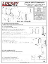
installation oF tHe electronic lock:
1. Remove the three (3) hole protectors from the middle of the vault door if installed.
2. For all units, attach the dial mounting plate to the outside of the door using the two (2) shoul-
der screws supplied. Make sure the word “UP” stamped on the front of the dial plate is facing
up when the mounting holes are positioned vertically.
3. Thread the plastic disc over the electronic locks data cable. Ensure the alignment pins mate
with the lock panel. Note the mounting slots on the lock
Metal
Peg
Plastic
disc
Mounting
Slots
Screws
with
Brass
Shoulders
Dial
Mounting
Plate
Figure 2. Vertically mounted electronic lock.
Door Hole
Deadbolt Assembly
Connector
Deadbolt Bushing
Mounting
Plate
Face Plate
Brass Spindle
Panel Bushing
Combination Panel

6
Model 8100 electronic lock Field installation Guide
P/N 02600-00000 1.02 in
4. The correct sized brass spindle (1.02 in) is supplied with the
installation kit.
5. Insert the Brass spindle into the back of the electronic lock
as shown, (with the notches opposite) be careful not to
pinch or cut the data cable.
6. Feed the data cable through the door (center of the lock back plate). The notches in the lock will
t over the brass standoffs.
Turn the lock to the right until it “seats” fully onto the backing plate.
If the lock will not turn on the standoffs, loosen each 1/4 turn until the lock “seats”. Seating of the
lock should be snug but not forced. Turn the lock back to the left until it is vertical.
7. With the lock face held in place, slide the remaining plastic spacer over the data cable from the
back. Ensure the slot in the spacer is aligned with the slot in the spindle (to the left).
8. Form a loop in the data cable and route it to the right as shown. Make sure the cable is below
the upper right threaded hole and is not pinched by the brass spindle.
9. Ensure the lock dead bolt is EXTENDED by pulling on it with
your ngers. With the loop in place, put the lock body over
the retaining holes on the door. Make sure the cable is not
“pinched” by the lock. The Brass spindle slides into the lock
body.
Plastic
Spacer
Cable
Routing
Spindle
Notch
Lock
Notch
Place Lock
Turn Right
Turn Left to Vertical

7
Model 8100 electronic lock Field installation Guide
10. Secure the lock body with the three (3) brass
screws.
11. Open the battery box and install the bat-
tery. Ensure the battery box cover does not
pinch the wire when installed. Route the
wire through the large hole in the battery
box. Clean the side of the cabinet with al-
cohol. Remove the backing from the sticky
tape, and press the battery box rmly to the
side of the cabinet. Ensure there is suf-
cient slack in the battery cable to open the
door fully.
12. Connect the data cable to the upper con-
nector, and the battery cable to the lower
connector. The locks receptacle is spring
loaded. Push for connector installation.
13. Attach the lock latch bar to the end of the
deadbolt with two (2) screws supplied. The
bar slides through the mount on the door.
The doors latch mechanism should be in the
closed position, and the dead bolt extended
in the locked position. The lock latch bar
should intersect the door latch bracket.
14. Bundle the wires and Ty-wrap as shown. En-
sure there is no possibility of the wires be-
coming pinched in the hinge. Ensure there
is enough slack in the battery cable to open
the door
DO NOT CLOSE THE DOOR!!
Place something between the door and the cab-
inet to ensure the door does not close.

8
Model 8100 electronic lock Field installation Guide
INITIAL TESTING OF THE LOCK (DOOR OPEN)
1. Enter the default combination ‘1-2-3-4-5-6’ observe one (1) beep after each digit and two (2)
beeps after the last, and turn the combination dial “clockwise” to open the lock. DO NOT SHUT
THE VAULT DOOR !!! Test operation of the T handle.
2. Install the latch work cover back onto the door, if supplied.
3. Proceed to the next section to CHANGE the combination to the lock. Do NOT leave the default
combination in the lock !!!
WARNING !!!!
MAKE SURE THE ELECTRONIC LOCK WORKS CORRECTLY WITH THE
INTENDED COMBINATION BEFORE CLOSING THE VAULT DOOR!!!
REPLACEMENT OF THE KEY LOCK
1. Remove the nut retaining the locking cam,
and remove the cam.
2. Remove the key lock retaining nut, and the
key lock assembly.
Retaining Nut
Cam
Retaining Nut
1. Place the T handle mechanism into the
door from the outside.
2. Secure the T handle with a lock washer and
the retaining nut. The T handle should be
turned fully to the left. Turn the handle to
the right to ensure smooth operation, then
back to the left.
3. Position the large silver locking cam on the
end of the T handle so that it will engage
the door closing mechanism. Note the
mounting hole is off center.
4. Secure the cam with the supplied bolt. Turn
the T handle slightly to the right to ensure
the cam will open the latch mechanism.
Retaining Bolt
Cam

9
Model 8100 electronic lock Field installation Guide
ElEctronic lock Audio rEsponsE signAls (BEEps)
Valid Code Entry - Double signal (beeps) after valid six (6) digit code is entered.
Invalid Code Entry - Triple signal (beeps). Old code is still valid.
Low Battery Signal - Repetitive beeping when any key is pressed. Replace the battery.
Operating the Electronic Lock (LaGard)
The electronic lock combination consists of six digits. The factory default combination is preset to
1-2-3-4-5-6.
EntEring thE comBinAtion
1. With the vault door OPEN, enter the factory default combination (1-2-3-4-5-6). The lock should
beep as each digit is entered (keypress). After the nal digit of the preset combination has been
entered, the lock should beep twice. The operator will have approximately 4 seconds to turn
the dial clockwise (which will retract the deadbolt). If the dial is not rotated within the specied
time frame, it will be necessary to re-enter the correct combination before the dial can be turned.
• In normal operation (with the vault door closed), once the correct combination has been entered
and the deadbolt is retracted, the vault door may be opened.
lockout FEAturE
The electronic lock incorporates a ‘Wrong Try Penalty’ lockout feature that is intended to prevent
entry from unauthorized personnel.
This feature works as follows:
• Four (4) consecutive attempts to enter an invalid combination will start a 5-minute timeout (pre-
set delay period before a combination can be entered again).
* The LED on the face of the lock will ash red at ten (10) second intervals.
• Following the initial delay period, two (2) more consecutive attempts to enter invalid combina-
tions will start another 5-minute timeout.
chAnging thE lock comBinAtion
With the door OPEN:
1. Enter six (6) zeros ‘0’.
2. Enter the current combination (factory default is set to 1-2-3-4-5-6).
3. Enter the new six (6) digit combination twice.
* If a mistake is made, wait thirty (30) seconds and repeat the rst 3 steps.
4. The combination is now changed to the new combination.
* Test the new lock combination several times before closing the door!!!
/