Page is loading ...

sec.3d
−−−−
1
2GO! - Technical manual
WALL-MOUNTED PANEL
Mod. 1128
TECHNICAL FEATURES ..................................................................2
CASES WITH FRONT FOR
OUTDOOR HOUSE PHONE STATION .............................................2
DOOR PHONE DOOR UNITS Ref. 1082/101 ...................................3
Performance .................................................................................3
Structure .......................................................................................3
Description of terminal boards .....................................................3
Technical specifi cations ...............................................................3
Default programming ....................................................................3
Function ........................................................................................3
Volume regulation .........................................................................4
Installation ....................................................................................4
CASINGS WITH OUTDOOR VIDEO HOUSE PHONE STATION ......5
Performance .................................................................................5
Structure .......................................................................................5
Description of terminal boards .....................................................5
Technical specifi cations ...............................................................5
Default programming ....................................................................6
Camera lens direction adjustment ................................................6
PUSH-BUTTONS ............................................................................6
Button type selection....................................................................6
Push-button and name tag assembly ..........................................6
SPECIAL MODULES ........................................................................7
LED COLOUR ...................................................................................7
PANEL INSTALLATION ....................................................................7
INSTALLING CASINGS SIDE BY SIDE ............................................9
Flush-mounting...........................................................................10
VIDEO DOOR PHONE SYSTEMS -
Examples of modular constructions with various capacities ......... 12
DOOR PHONE SYSTEMS -
Examples of modular constructions with various capacities ......... 15
Download from www.urmetdomus.com Technical Manuals area.
SECTION CONTENTS
Some products may be described in the “New” section.§
SECTION 3D
(REV.D)

PANELS
2
−−−−
sec.3d
2GO! - Technical manual
WALL-MOUNTED PANEL Mod. 1128
WALL-MOUNTED PANEL Mod. 1128
TECHNICAL FEATURES
CASES WITH FRONT FOR OUTDOOR HOUSE PHONE STATION
WALL-MOUNTED PANEL Mod. 1128
The push-button panels Mod. 1128 are the ideal compromise
between inexpensiveness, design, straightforward installation and
communicating effi ciency for making door phone systems and video
door phone systems.
All the push-button panels can be installed rested on the wall with
screws and plugs keeping a low projection from the wall: just 41mm.
In consideration of its reduced width, installation of the push-button
panel is also possible on a gatepost.
The push-buttons, which also act as transparent cover for the name
tag, are modular and come in two versions with different sizes.
The following three models of push-button panels are available: set-
up for outdoor house phone station, set up for outdoor video house
phone station, and set-up for push-buttons only. Every model is
available in two different colours: Anthracite and grey.
The additional casings with push-buttons only can be fi tted at the side
of those set up for the outdoor station, thereby making it possible to
make systems with a maximum of 32 pushbuttons.
These panels may be used to make door phone systems without
camera unit.
In the case of particular requirements the push-button panel can be
fl ush-fi tted using the specifi c box Ref. 1128/51, in this case, protrusion
from the edge of the wall is reduced to a few millimetres.
TECHNICAL FEATURES
Dimensions: 246 x 99 x 41mm
Material: ABS base and hood Anodised aluminium front
Name tag: small button 20 x 60mm
big button 40 x 60mm
Name tag lighting: RGB customisable colour LED
Name tag light power: 12Vac
Name tag light draw: see housing description
Working temperature range: -10 ÷ 50°C
Degree of protection: IP44
§
CASES WITH FRONT FOR OUTDOOR HOUSE
PHONE STATION
The casings with front for outdoor house phone station come in two
versions of different colour:
Anthracite Ref. 1128/44
Grey Ref. 1128/45
In both it is possible to install up to 4 small push-buttons (20 x 60mm)
or up to 2 large push-buttons (40 x 60mm).
The casings are supplied with refl ecting bases with the related lighting
circuit with leds with a maximum uptake of 30mA.
8
2
57 46
3
1
1
Programming button
2
Calling buttons
3
Connector for connecting buttons modules
4
Connector for connecting supplementary buttons modules
5
External power 12V~ selector jumper
6
Terminals for name tag lighting power
7
Name tag lighting LED connector
8
Installed button type selection jumper (small or large)
DESCRIPTION OF TERMINALS
~0
}
Name tag light power from external transformer
~12
An external transformer capable of providing a voltage of 12Vac
and a current of 30mA is required for the casing alone, with
additional 58mA for each button casing connected to the door
unit.
•
•
§

PANELS
sec.3d
−−−−
3
2GO! - Technical manual
WALL-MOUNTED PANEL Mod. 1128
WALL-MOUNTED PANEL Mod. 1128
DOOR PHONE DOOR UNITS Ref. 1082/101
DOOR PHONE DOOR UNITS Ref. 1082/101
PERFORMANCE
Installable in 1128 supports.
Possibility of connecting up to 32 user buttons in total for each door
unit without the addition of expansion modules.
Programming entirely with dip switches also when device is not
powered.
Possibility of code sequences to calling buttons using dip
switches.
Possibility of programming one or more buttons for controlling a
special decoder (“staircase lights” function).
60 second pick-up waiting time (system busy).
2 minute maximum conversation time from handset pick-up.
Call and end of conversation confi rmation tones.
Lock control actuator with capacitance pulse discharge.
Free and privacy function electrical lock management.
Arrangement for activating electrical lock by pressing button inside
hall.
Open door sensor input.
Speaker and microphone volume adjustment trimmer.
Connection with button module via connector.
Set-up for connecting external surveillance cameras or 1128
camera.
STRUCTURE
5
4
1
2
3
7
8
6
1
External camera connector for surveillance or video camera
Mod. 1128
2
Microphone volume adjustment trimmer
3
Connector for buttons module
4
Microphone
5
Terminals
6
Programming dip switch
7
Line terminal switch
8
Fonic level regulation
•
•
•
•
•
•
•
•
•
•
•
•
•
•
•
DESCRIPTION OF TERMINAL BOARDS
LINE
}
Non-polarised bus line
LINE
V3
}
Secondary surveillance camera connection
V5 (in addition to the one connected to connector “1”)
T Ref. 1038/69 relay box output for surveillance camera cycle
function
PA Hall door opener button input
SP Open door sensor contact input
GND
}
Reference ground for PA, SP
GND
SE+ Positive electrical lock operation
SE- Negative electrical lock operation
TECHNICAL SPECIFICATIONS
Max. Active consumption (audio): 300mA
Max. stand-by consumption: 70mA
Line termination: 104,4 Ohm±1%
Working temperature range: -10 ÷ 50°C
DEFAULT PROGRAMMING
The default settings of the device are:
Door unit number: 2 (slave)
Station type: Main
Electrical lock management: Privacy
First button user code: 0
Line termination: ON
CODE
AUX
ON
ID
Z
4321 5
4321
FUNCTION
CALL FORWARDING
Up to 32 users can be called by pressing the corresponding buttons
on the panel associated to the door unit.
The following cases may occur when a call button is pressed according
to the state of the door unit:
The line is free: the door unit will output the call forwarding tone (3
beeps in sequence). The door unit will output an end of conversation
tone (5 beeps in rapid sequence) at the end of the communication.
The line is busy: the door unit will output a warning tone (5 beeps
in sequence) and the yellow LED on the front will blink until busy
mode ends. Press the call button again when busy mode ends.
ELECTRICAL LOCK MANAGEMENT
The door units have two terminals for electrical lock capacitance
discharge (SE-, SE+). The electrical lock is controlled in the following
cases:
Whenever the hall button is pressed (terminals PA, GND).
When a door open command is received from an apartment station
according to the confi guration of the AUX dip switch “free” or
“privacy” (see “2GO! system” paragraph “Door unit functions”).
Use timer Ref. 1032/81 to control electrical locks requiring longer
timing.
•
•
•
•

PANELS
4
−−−−
sec.3d
2GO! - Technical manual
WALL-MOUNTED PANEL Mod. 1128
WALL-MOUNTED PANEL Mod. 1128
CASING WITH FRONT
VOLUME REGULATION
Volume levels are calibrated by default so not to require adjustments
in most cases.
Use a screwdriver to adjust the trimmers if required.
INSTALLATION
Proceed as follows to install the door unit in casing Ref. 1128/44 or
-/45.
2
3
1
CASING WITH FRONT
The casings with front come in two versions of different colour:
Anthracite Ref. 1082/40
Grey Ref. 1082/41
These casings, which are already set up with the Name tag light power
circuit, make it possible to increase the number of users that can be
called. Indeed, it is possible to install up to 10 small push-buttons (20
x 60mm) or up to 5 large push-buttons (40 x 60mm) on them.
The casings with front can be installed at the side of any other
pushbutton panel, using the special fairlead shims provided and
following the instructions given in the “Installing casings side by side”
paragraph.
The casings are supplied with fi ve refl ecting bases with the related
lighting circuit with leds.
2
1
5
34
1
Name tag lighting LED connector
2
Calling buttons
3
Connector for button module connection
4
Connector for connecting the previous button module or door
unit module
5
Refl ecting bases
•
•

PANELS
sec.3d
−−−−
5
2GO! - Technical manual
WALL-MOUNTED PANEL Mod. 1128
CASINGS WITH OUTDOOR VIDEO HOUSE
PHONE STATION
The casings with outdoor video house phone station are provided with
colour camera with coaxial cable, door unit and 2 small pushbutton
(20 x 60mm)
The casings with front for outdoor video house phone station come in
two versions of different colour:
Anthracite Ref. 1082/10
Grey Ref. 1082/11
The casings are supplied with refl ecting bases with the related lighting
circuit with leds with a maximum uptake of 30mA.
PERFORMANCE
Two pre-wired calling buttons.
Possibility of connecting up to 32 user buttons in total for each door
unit without the addition of expansion modules.
Possibility of connecting up to three door units in system.
Fixed focus colour camera with integrated optics and shutter.
Possibility of adjusting lens direction.
Integrated subject light.
Possibility of code sequences to calling buttons using dip
switches.
Programming entirely with dip switches also when device is not
powered.
Possibility of programming one or more buttons for controlling a
special decoder (“staircase lights” function).
60 second pick-up waiting time (system busy).
2 minute maximum conversation time from handset pick-up.
Call and end of conversation confi rmation tones.
Lock control actuator with capacitance pulse discharge.
Free and privacy function electrical lock management.
Arrangement for activating electrical lock by pressing button inside
hall.
Open door sensor input.
Speaker and microphone volume adjustment trimmer.
Installation test function terminals.
Management of external coaxial video input for surveillance
cameras.
Relay box control for cyclic management of several surveillance
cameras.
•
•
•
•
•
•
•
•
•
•
•
•
•
•
•
•
•
•
•
•
•
•
STRUCTURE
2
1
2
3
4
13
14
15
16
6
12
911 8 710
5
1
Subject lighting LED
2
Camera
3
Microphone volume adjustment trimmer
4
Terminals
5
Calling buttons
6
Programming button
7
Microphone
8
Connector for connecting buttons modules
9
External power 12V~ selector jumper
10
Terminals for name tag lighting power
11
Name tag lighting LED connector
12
Installed button type selection jumper (small or large)
13
Refl ecting bases
14
Programming dip switch
15
Line terminal switch
16
Fonic level regulation
DESCRIPTION OF TERMINAL BOARDS
LINE
}
Non-polarised bus line
LINE
V3
}
Secondary surveillance camera connection
V5 (in addition to the one already present in the casing)
T Ref. 1038/69 relay box output for surveillance camera cycle
function
PA Hall door opener button input
SP Open door sensor contact input
GND
}
Reference ground for PA, SP
GND
SE+ Positive electrical lock operation
SE- Negative electrical lock operation
TECHNICAL SPECIFICATIONS
Max. Active consumption (video + audio): 300mA
Max. stand-by consumption: 60mA
Line termination: 104,4 Ohm±1%
Shooting sensor: CCD 1/3”
Built-in lens: series mounted
Octurator: series mounted
Focus: fi xed
Minimum lighting for an acceptable imag: 0,2lux
Working temperature range: -10 ÷ 50°C
WALL-MOUNTED PANEL Mod. 1128
CASINGS WITH OUTDOOR VIDEO HOUSE PHONE STATION

PANELS
6
−−−−
sec.3d
2GO! - Technical manual
WALL-MOUNTED PANEL Mod. 1128
DEFAULT PROGRAMMING
The default settings of the device are:
Door unit number: 1
Station type: Main
Electrical lock management: Privacy
First button user code: 0
Line termination: ON
CODE
AUX
ON
ID
Z
4321 5
4321
FUNCTION
CALL FORWARDING
Up to 32 users can be called by pressing the corresponding buttons
on the panel.
The following cases may occur when a call button is pressed according
to the state of the door unit:
The line is free: the door unit will output the call forwarding tone (3
beeps in sequence). The door unit will output an end of conversation
tone (5 beeps in rapid sequence) at the end of the communication.
The line is busy: the door unit will output a warning tone (5 beeps
in sequence) and the yellow LED on the front will blink until busy
mode ends. Press the call button again when busy mode ends.
ELECTRICAL LOCK MANAGEMENT
The door units have two terminals for electrical lock capacitance
discharge (SE-, SE+). The electrical lock is controlled in the following
cases:
Whenever the hall button is pressed (terminals PA, GND).
When a door open command is received from an apartment station
according to the confi guration of the AUX dip switch “free” or
“privacy” (see “2GO! system” paragraph “Door unit functions”).
Use timer Ref. 1032/81 to control electrical locks requiring longer
timing.
VOLUME REGULATION
Volume levels are calibrated by default so not to require adjustments
in most cases.
Use a screwdriver to adjust the trimmers if required.
CAMERA LENS DIRECTION ADJUSTMENT
After installation, the camera direction can be adjusted according
to the position of the framed subject. This operation may be carried
out manually after removing the frame and the extractable front by
adjusting the jointed mount directly from the front. The frame does not
need to be tipped and special tools are not required.
5°
10°
5° 5°
•
•
•
•
PUSH-BUTTONS
The push-buttons to be installed on the various casings are to be
bought separately and come in two versions with different sizes:
Small button 20 x 60mm Ref. 1128/1
Big button 40 x 60mm Ref. 1128/2
The push-buttons are supplied complete with:
Button body that can be clipped onto the base of the push-button
panel.
Transparent protective cover with indication of pressing point.
Support for installation and clipping onto the casings.
Transparent name tag.
Name tag lighting diffuser.
The large push-buttons should always be positioned in
correspondence with the refl ecting chambers and not
superimposed on two of them.
BUTTON TYPE SELECTION
Use jumper 1 on door unit casing or camera casing to select the type
of buttons.
Jumper inserted to make small button panels Ref. 1128/1 (default).
Jumper not inserted to make large button panels Ref. 1128/2.
PUSH-BUTTON AND NAME TAG ASSEMBLY
CLICK
5
6
7
8
1
2
3
4
9
10
5
6
7
8
9
10
1
2
3
4
ATTENTION!
Rear view
Fit the support with the transparent cover starting from the top
downwards.
•
•
•
•
•
•
•
§
•
WALL-MOUNTED PANEL Mod. 1128
PUSH-BUTTONS

PANELS
sec.3d
−−−−
7
2GO! - Technical manual
WALL-MOUNTED PANEL Mod. 1128
WALL-MOUNTED PANEL Mod. 1128
SPECIAL MODULES
LED COLOUR - PANEL INSTALLATION
CLICK
Rossi
Rossi
Rossi
The fi gures above refer to the installation of a small pushbutton,
the large push-button Ref. 1128/2 should be installed in the
same way.
To remove the supports with transparent cover use a screwdriver and
lever on the fastening catches.
5
6
7
8
9
10
1
2
3
4
SPECIAL MODULES
In replacement of the push-buttons the following special modules can
be installed:
Anthracite blank modules
(dimensions 20 x 60mm): Ref. 1128/30
Grey blank modules
(dimensions 20 x 60mm): Ref. 1128/31
Transparent module with tag for house number
(dimensions 40 x 60mm): Ref. 1128/5
The installation procedures are the same as those described for
the push-buttons.
§
•
•
•
§
LED COLOUR
1. Press the button to program the LED colours.
Button 1
Button 2
LED colour programming button
2. Press button 2 to scroll the colour palette. Press button 1 to go
back to palette selection.
There are 37 available colours are proposed as follows: light
with colours traditionally used for panels (emerald green, blue,
amber, light green), switch-off, 33 customised colour lights. The
LEDs will go out at the end of the sequence. Press button 2
again to repeat the sequence from the beginning.
3. After selecting the colour, press the programming button to end
the colour selection procedure.
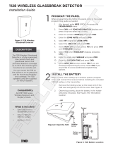
PANEL INSTALLATION
Remove the refl ecting bases, the door unit with camera where
applicable.
1
2
Fasten the casing base on a fl at wall, at the height shown in the
fi gure, using the screws (A) and wall plugs (B) provided or on a box
Mod. 503.
§
•
•

PANELS
8
−−−−
sec.3d
2GO! - Technical manual
WALL-MOUNTED PANEL Mod. 1128
1,55 m ÷ 1,65 m
B
B
A
A
Mod. 503
B
A
Insert the door unit and the microphone on the base of the specifi c
housing.
Connect the wires (it is advisable to have the wire protrude from the
wall by approximately 50mm).
•
•
To power the name tag light LEDs with supplementary power in
addition to system power, use a Ref. 9000/230 transformer for each
panel and position the jumper.
PRI
NO
PRI
PRI
YES
Jumper in position 1: no external power (default).
Jumper in position 2: external power.
Ref. 9000/230
Fasten the name tag light circuit.
1
2
•
WALL-MOUNTED PANEL Mod. 1128
PANEL INSTALLATION

PANELS
sec.3d
−−−−
9
2GO! - Technical manual
WALL-MOUNTED PANEL Mod. 1128
Connect the door unit to the button module with the provided
wire.
Adjust the volume and position of the camera (if present).
Fit the support with the transparent cover starting from the top
downwards as shown in the fi gure below.
CLICK
Write the name on the name tags and insert them in the housings.
Rossi
CLICK
Rossi
•
•
•
•
Insert the front part of the panel on the base and fasten it with the
socket head screw using the wrench (2mm) provided.
C
99 mm
240 mm
35 mm
INSTALLING CASINGS SIDE BY SIDE
The casings can be joined together using the special fairlead shims
(provided) either vertically or horizontally.
The shims are hollow to allow the passage of wires from one
pushbutton panel to the other.
HORIZONTAL INSTALLING
SIDE BY SIDE
VERTICAL INSTALLING
SIDE BY SIDE
•
WALL-MOUNTED PANEL Mod. 1128
INSTALLING CASINGS SIDE BY SIDE

PANELS
10
−−−−
sec.3d
2GO! - Technical manual
WALL-MOUNTED PANEL Mod. 1128
1
2
Connect the buttons of the various modules with the wire provided
passing it through the wire grommet.
Refi t the buttons and the refl ecting bases on the respective
modules.
Complete installation by inserting the protective glass, the name
tags and the frontal part.
FLUSH-MOUNTING
For fl ush-mounting the push-button panel the special box must be
purchased separately (Ref. 1128/51), then proceed as follows:
Make the hole for letting through the connection wires before
closing the fl ush-mounting box.
Embed the box in the wall.
NO
•
•
•
•
•
To install a casing with buttons only at the side of a casing for outdoor
station proceed as follows:
Remove refl ecting bases and buttons from the module.
1
2
Take out the removable plug of the casing on the side for which
installation is required.
Remove the outer wall in correspondence of the holes left by the
plugs with the help of fl at-nosed pliers.
Insert the fairlead shims and join the two casings.
HORIZONTAL INSTALLING SIDE BY SIDE
D
CLICK
A long nose pliers
is suggested
VERTICAL INSTALLING SIDE BY SIDE
A long nose pliers
is suggested
CLICK
D
Fix the bases to the wall
Remove the refl ecting bases and the buttons from the door unit
module.
•
•
•
•
•
•
WALL-MOUNTED PANEL Mod. 1128
INSTALLING CASINGS SIDE BY SIDE

PANELS
sec.3d
−−−−
11
2GO! - Technical manual
WALL-MOUNTED PANEL Mod. 1128
Fasten the frame provided to the box.
Screw the casing base to the frame.
Complete installation as described in the previous paragraphs
according to the type of casing.
For installing push-button panels side by side, special fairlead
shims are provided to be placed between the fl ush-fi tting
boxes.
•
•
•
§
HORIZONTAL INSTALLING SIDE BY SIDE
VERTICAL INSTALLING SIDE BY SIDE
WALL-MOUNTED PANEL Mod. 1128
INSTALLING CASINGS SIDE BY SIDE

PANELS
12
−−−−
sec.3d
2GO! - Technical manual
WALL-MOUNTED PANEL Mod. 1128
VIDEO DOOR PHONE SYSTEMS
EXAMPLES OF MODULAR CONSTRUCTIONS WITH VARIOUS CAPACITIES
With large buttons
BUTTONS NUMBER
BUTTONS NUMBER
COMMON
PRODUCTS
ANTHRACITE
(*)
Buttons
Casings with outdoor video house phone station
Casing with front
Blank module (@)
GRAY
(*)
ACCESSORIES
Casings with outdoor video house phone station
Blank module (@)
Casing with front
Flush mounting box
1128/2
1082/10
1082/40
1082/11
1082/41
1128/31
1128/51
1128/30
(*) alternatives
(@) as an alternative to two blank modules it is possible to install
a house number module Ref. 1128/5
With small buttons
BUTTONS NUMBER
BUTTONS NUMBER
COMMON
PRODUCTS
ANTHRACITE
(*)
Buttons
Casings with outdoor video house phone station
Casing with front
Blank module (@)
GRAY
(*)
ACCESSORIES
Casings with outdoor video house phone station
Blank module (@)
Casing with front
Flush mounting box
1128/1
1082/10
1082/40
1082/11
1082/41
1128/31
1128/51
1128/30
(*) alternatives
(@) as an alternative to two blank modules it is possible to install
a house number module Ref. 1128/5
1 2 3 4 5 6 7 8 9 10111213141516
1 2 3 4 5 6 7 8 9 10111213141516
1
222 22233
111 1 111111
11
1111
11
112222
11
111 1 1111111 11111
1
1212112211
33
17 18 19 20 21 22 23 24 25 26 27 28 29 30 31 32
17 18 19 20 21 22 23 24 25 26 27 28 29 30 31 32
444 44444
111 1 1111111 111
222222
333333
11
111 1 1111111 11111
3333333333
44
519673248
519673248
519673248
519673248
1 2 3 4 5 6 7 8 9 10 11 12 13 14 15 16 17 18 19 20 21 22 23 24 25 26 27 28 29 30
1111 1 2121122
112222223333333333
519673248
519673248
1 2 3 4 5 6 7 8 9 10111213141516
1 2 3 4 5 6 7 8 9 10111213141516
333 34344
111 1 111111
11
1111
11
212222
11
1
1
8
11 1 1111111 1111
2648
1
2323223332
44
862 4264
82648862 4264
1111 2 323223332
1 2 3 4 5 6 7 8 9 10111213141516
WALL-MOUNTED PANEL Mod. 1128 - VIDEO DOOR PHONE SYSTEMS

PANELS
sec.3d
−−−−
13
2GO! - Technical manual
1 2 3 4 5 6 7
8 9 10 11
12 13 14
15 16
WALL-MOUNTED PANEL Mod. 1128
VIDEO DOOR PHONE SYSTEMS
EXAMPLES OF MODULAR CONSTRUCTIONS WITH VARIOUS CAPACITIES
WALL-MOUNTED PANEL Mod. 1128 - VIDEO DOOR PHONE SYSTEMS

PANELS
14
−−−−
sec.3d
2GO! - Technical manual
3 4 5 6 7 8
1 2
9 10 11 12 13 14
15 16 17 18
20 21 22 23
24 25 26
27 28 29
30 31 32
19
WALL-MOUNTED PANEL Mod. 1128
VIDEO DOOR PHONE SYSTEMS
EXAMPLES OF MODULAR CONSTRUCTIONS WITH VARIOUS CAPACITIES
WALL-MOUNTED PANEL Mod. 1128 - VIDEO DOOR PHONE SYSTEMS

PANELS
sec.3d
−−−−
15
2GO! - Technical manual
With large buttons
BUTTONS NUMBER
BUTTONS NUMBER
COMMON
PRODUCTS
ANTHRACITE
(*)
Buttons
Casings with outdoor video house phone station
Casing with front
Blank module (@)
GRAY
(*)
ACCESSORIES
Casings with outdoor video house phone station
Blank module (@)
Casing with front
Flush mounting box
1128/2
Door unit 1082/101
Door unit 1082/101
1128/44
1082/40
1128/45
1082/41
1128/31
1128/51
1128/30
(*) alternatives
(@) as an alternative to two blank modules it is possible to install
a house number module Ref. 1128/5
With small buttons
BUTTONS NUMBER
BUTTONS NUMBER
COMMON
PRODUCTS
ANTHRACITE
(*)
Buttons
Casings with outdoor video house phone station
Casing with front
Blank module (@)
GRAY
(*)
ACCESSORIES
Casings with outdoor video house phone station
Blank module (@)
Casing with front
Flush mounting box
1128/1
1128/44
1082/40
1128/45
1082/41
1128/31
1128/51
1128/30
(*) alternatives
(@) as an alternative to two blank modules it is possible to install
a house number module Ref. 1128/5
1 2 3 4 5 6 7 8 9 10 11 12 13 14 15 16
1 2 3 4 5 6 7 8 9 10 11 12 13 14 15 16 17
233 33344
11
2
11111111
11
1111
11
112222
11
111 1 1111111 11111
2313223322
44
1111 2 313223322
1 2 3 4 5 6 7 8 9 10 11 12 13 14 15 16
17
1
111 1 1111111 111111
1
3
4
3
17
82648862 4264
14 1324431 2132
1 2 3 4 5 6 7 8 9 10 11 12 13 14 15 16
1 2 3 4 5 6 7 8 9 10 11 12 13 14 15 16
222 22222
111 1 1111111 111
111221
11
111 1 1111111 11111
33
17 18 19 20 21 22 23 24 25 26 27 28 29 30 31 32
31 32
17 18 19 20 21 22 23 24 25 26 27 28 29 30 31 32
334 44444
111 1 1111111 111
333333
11
111 1 1111111 11111111 1 1111111 11111
111 1 1111111 11111
11 1 2121111112222223323333332
44
1 2 3 4 5 6 7 8 9 10 11 12 13 14 15 16 17 18 19 20 21 22 23 24 25 26 27 28 29 30
519673248
519673248
519673248
519673248
59673248
59673248
132
132
11 1 2121111112222223323333332
WALL-MOUNTED PANEL Mod. 1128
DOOR PHONE SYSTEMS
EXAMPLES OF MODULAR CONSTRUCTIONS WITH VARIOUS CAPACITIES
WALL-MOUNTED PANEL Mod. 1128 - DOOR PHONE SYSTEMS

PANELS
16
−−−−
sec.3d
2GO! - Technical manual
2
9
13 14
16 17
10
3 4 5 6 7
8 11
12
15
1
WALL-MOUNTED PANEL Mod. 1128
DOOR PHONE SYSTEMS
EXAMPLES OF MODULAR CONSTRUCTIONS WITH VARIOUS CAPACITIES
WALL-MOUNTED PANEL Mod. 1128 - DOOR PHONE SYSTEMS

PANELS
sec.3d
−−−−
17
2GO! - Technical manual
5 6 7 8
9
10 12 13 1411
1 2 3 4
15
22 23 2421
16 17 18 19 20
25 26 27
28 29 30
31 32
WALL-MOUNTED PANEL Mod. 1128
DOOR PHONE SYSTEMS
EXAMPLES OF MODULAR CONSTRUCTIONS WITH VARIOUS CAPACITIES
WALL-MOUNTED PANEL Mod. 1128 - DOOR PHONE SYSTEMS

PANELS
18
−−−−
sec.3d
2GO! - Technical manual
/