Page is loading ...

Page 1
CruzPro
MaxVu110
User Configurable
Multifunction Instrument

Page 2
Other CruzPro Products
lDepthsounders/w Keel Offset, Deep/Shallow/Anchor Drag Alarms
lPC Based DSP Fishfinder for Windows98, NT, SE,XP, 2000
lSpeed/Temperature/Logs
lDigital DC Volts Gauge/w Alarms
lDigital DC Volts Gauge/w Alarms for 3 Battery Banks
lDigital Amps Gauge
lDC Volts/Amps/Amp-Hour Monitors
lAC Volts/Amps/Freq/kW Monitors
lLPG/Petrol Gas Detectors/Alarms
lBilge Water Alarms/w Stainless Steel Water Sensor
lIntelligent Bilge Pump Controllers/w Stainless Steel Water Sensors
lIntelligent Windlass Controller/Chain Counters
lDigital Fuel Gauges & Fuel Consumption Calculator
lDigital Tank Level Gauges for 1 or 3 Tanks /w Separate Alarms
lSmart 4 step Alternator Regulator
lMarine Security System/w Reliable Intrusion Sensors
lRPM/Engine Hours/Elapsed Time Gauges/w Alarm
lDigital Engine Temperature Gauge/w Alarms
lDigital Oil Pressure Gauge/w Alarms
lDigital Temperature Gauges for 1 or 3 Areas /w Alarms
lDigital Clock/Watch/Race Timers/w 8 Alarms
l8 and 16 Amp Light Dimmers / Motor Speed Controller
lSolar Panel Charge Controllers 6/8/9 & 20 Amps
l4 & 8 Channel NMEA Combiners/RS-232 Convertors
lEngine/Exhaust Temp. Monitor & Digital Pyrometer
lNMEA 0183 Remote Data Repeater/w 4 Input Channels
lHigh Pressure Digital Hydraulic Pressure Gauge
lEngine Hours/Elapsed Trip Time/Engine Maintenance Alarm Gauge
2007 CruzPro Ltd.
email: [email protected] MaxVu110 Manual Ver. BI
website: www.cruzpro.com Made in New Zealand

Page 3
Table of Contents
Introduction . . . . . . . . . . . . . . . . . . . . . . . . . . . . 5
Table of Standard Data Sources . . . . . . . . . . . . 7
Installation and Wiring . . . . . . . . . . . . . . . . . . . 9
Operation of the MaxVu110 . . . . . . . . . . 13
Key Functions . . . . . . . . . . . . . . . . . . . . . . . . . . . 13
Turning Display ON/OFF . . . . . . . . . . . . . . . . . . 13
Changing and Controlling Backlight Intensity . . . . . . . 13
Selecting a Display Configuration . . . . . . . . . 13
Turning Alarms ON/OFF . . . . . . . . . . . . . . . . . 20
Setting High and Low Alarm Values . . . . . . . . . . . . . . 20
Setting/Starting Clock/Time-Of-Day Alarms/Race Timers . . 21
Calibrating a Data Source . . . . . . . . . . . . . . . . . 23
Setting Display Damping . . . . . . . . . . . . . . . . 24
Setting Units of Measure . . . . . . . . . . . . . . . . 25
Setting Tachometer Sensitivity . . . . . . . . . . . . . . . . 26
Setting Tachometer Pulley Ratio . . . . . . . . . . . . 26
Clear Trip Fuel, Trip Distance and Trip Time . . . . 26
Operation of the Windows Software . . . . . . . 27
Software Installation . . . . . . . . . . . . . . . . . 27
USB Driver Installation (If required) . . . . . . . . . 28
Connecting to the MaxVu110 . . . . . . . . . . . . . 30
Main Screen . . . . . . . . . . . . . . . . . . . . 30
Display Configurations Area . . . . . . . . . . . . . . . . . . . 31
Current Display Configuration Area. . . . . . . . . . . . . . . . 31
Data Sources . . . . . . . . . . . . . . . . . . . . . . . 31
High and Low Alarm Values . . . . . . . . . . . . . . . . . . 32
High and Low Limit Values for Bar Charts . . . . . . . . 32
ICONS Area . . . . . . . . . . . . . . . . . . . . . . . . . . . . 33
Pulldown Menu Area . . . . . . . . . . . . . . . . . . . . . 33
Files Menu . . . . . . . . . . . . . . . . . . . . . . . 33

Page 4
Edit Menu . . . . . . . . . . . . . . . . . . . . . . . 34
View/Set Sender Curves . . . . . . . . . . . . 36
Help Menu . . . . . . . . . . . . . . . . . . . . . . . . 38
Selecting an NMEA Sentence to Display . . . . . . . . . 38
Uploading and Downloading Display Configurations
. . . . 40
Appendix A -
Specifications . . . . . . . . . . . . . . .
43
Appendix B -
Packing List . . . . . . . . . . . . . . .
45
Appendix C -
Typical Setup . . . . . . . . . . . . . . .
46
Appendix D -
Important Notes and Warnings . . . . . . .
48
(You MUST read this section carefully and completely)
Appendix E - Background Critical Alarm Functions
. . . . .
51
Appendix F - Key Function Summary . . . . . . . . . 53
Appendix G - NMEA 0183 Sentences . . . . . . . . . 56
Appendix H - Expansion With Optional Accessories . . . 62
Appendix I - Updating the Internal Firmware . . . . . . 63
Appendix J - Display Firmware Version and Serial No. . . 63
Appendix K - Error Codes . . . . . . . . . . . . . . . 64
Appendix L - Optional Items . . . . . . . . . . . . . . 65
Index - . . . . . . . . . . . . . . . . . . . . . . . . 66
Windows, WinXP, Win98, WinNT, Win2K and Vista are trademarks of Microsoft Inc.
CruzPro is a trademark of CruzPro Ltd.

Page 5
Introduction
The MaxVu110 user-configurable multifunction instrument will
simultaneously display five sets of data on three digital displays and
two bar graphs. Data to be displayed can be selected from 34
different “Data Sources” such as Boat Speed, Engine RPM, Tankage
Levels or NMEA 0183 data, etc. Independent high and low alarms
can be set for each data source (including NMEA 0183 data). All the
calibration curves and circuitry to measure the data are inside the
MaxVu110 so you do not need a “Brain Box” or “Black Box”.
The data being displayed, where it is displayed and the alarm limits
for each display is called a “Display Configuration”. You can switch
between sixteen different predefined display configurations with the
front panel key buttons. The display configurations are highly
flexible and any particular set of data can be directed to one the digital
displays and/or one of the two bar graphs. Each of the sixteen
display configurations can be edited to show the data that you want
to see from the available data sources. Changes are automatically
saved to a nonvolatile memory.
The MaxVu110 can display up to eight separate NMEA 0183 data
sentences arriving on four different NMEA 0183 inputs. You can
view NMEA 0183 data such as depth, wind speed/direction, GPS
bearing and distance to waypoint, exhaust gas temperature, etc. The
MaxVu110 recognizes thousands of different NMEA sentences.
Variable display damping (filtering) can be selected for RPM, Boat
Speed, Fuel, Tank Level, Trim Angle and four of the eight NMEA
0183 inputs.
You can select from five levels of backlighting and the MaxVu110
works on both 12 and 24 VDC. The internal software can be updated
via the internet to add additional features as they become available.

Page 6
A built-in editor enables you to change alarm levels, calibrate data
sources, select different calibration curves and change display
damping using the front panel keys.
The MaxVu110 is also supplied with software that runs under
Windows 98, WinXP, WinNT, Win2K ,Vista and Win 7 to simplify
editing of the Display Configurations, Alarms, set Units of Measure
and select Calibration Curves. You can create and edit custom
calibration curves for Engine Temperature, Oil Pressure, Fuel and
Tankage Levels and Trim Angle. Settings can be quickly uploaded
to the MaxVu110 or downloaded from the MaxVu110 using either
a RS232 port or USB port.

Page 7
Table 1 - MaxVu110 Standard Data Sources
The MaxVu110 contains built-in electronic circuitry to measure and display:
1 Engine RPM
2 Engine Temperature (Deg F, Deg C)
3 Engine Oil Pressure (PSI, Bars)
4 Engine Hours
5 Settable Downcounting Maintenance Alarm (Change engine oil or check
battery water or change water maker filters, etc.).
6 Fuel Remaining (Gallons, Liters)
7 Trip Fuel Used
8 Total Fuel Used
9 Boat Speed (Knots, MPH, Km/H)
10 Temperature #2 for Seawater, Engine Room, etc. (Deg F, Deg C)
11 Trip Log (Km. Miles, Naut. Miles)
12 Total Log (Km, Miles, Naut. Miles)
13 Time-of-Day Clock (12 or 24 hour format)
14 Elapsed Trip Time
15 Eight settable time-of-day alarms
16 Settable Downcounting Race Timer #1
17 Settable Downcounting Race Timer #2
18 Battery Bank #1 Volts
19 Battery Bank #2 Volts
20 Battery Bank #3 Volts
21 Second Tank Level Display (See Note 1 - Auxiliary Input #1)
22 Third Temperature Input (See Note 1 - Auxiliary Input #1)
23 NMEA 0183 input #1A (Display NMEA Depth, Wind, GPS data, etc)
24 NMEA 0183 input #1B (Display NMEA Depth, Wind, GPS data, etc)

Page 8
25 NMEA 0183 input #2A (Display NMEA Depth, Wind, GPS data, etc)
26 NMEA 0183 input #2B (Display NMEA Depth, Wind, GPS data, etc)
27 NMEA 0183 input #3A (Display NMEA Depth, Wind, GPS data, etc)
28 NMEA 0183 input #3B (Display NMEA Depth, Wind, GPS data, etc)
29 NMEA 0183 input #4A (Display NMEA Depth, Wind, GPS data, etc)
30 NMEA 0183 input #4B (Display NMEA Depth, Wind, GPS data, etc)
31 Remote Hardware Data Display #1 (For future expansion options)
32 Remote Hardware Data Display #2 (For future expansion options)
33 Trim Angle (See Note 1 - Auxiliary Input #1)
34 External Backlight ON/OFF control
Note 1 - Auxiliary Input #1. The Yellow #3 wire can be programmed to be:
a) Additional Tankage input (Water, fuel, holding tank - See Note 3)
b) Third Temperature input (See Note 4)
c) Trim Angle input (See Note 2)
Note2 - Engine temperature, oil pressure, trim angle and fuel senders are not
supplied. Transducers to measure boat speed, sea water temperature and depth
are not supplied but available separately.
Note 3 - Works with any standard resistive tank sender (European or Ameri-
can). Sender not supplied.
Note 4 - Temperature senders (such as seawater temperature, refrigerator tem-
perature, engine room or battery temperature, etc.) not supplied but available
separately in a variety of different formats.

Page 9
Installation and Wiring
Before starting the installation, please read this entire section first.
Finger tighten the screws that mount the instrument bracket - It is
not necessary or recommended to use tools.
!
Drill a 2-1/8" (55mm) mounting hole where you desire to mount
the instrument (Figure 1).
!
Remove the adhesive backing protection from the bulkhead
gasket and carefully align the waterproof bulkhead gasket on the back
of the instrument.
!
Connect the various wires as shown in Figures 2 and 3.
!
Carefully check all your wiring then mount the instrument in
the hole. Use only finger tension to tighten the bracket hold-down
nuts
Figure 1 - Mounting the Instrument

Page 10
Figure 2 - MaxVu110 Screw Terminal Connections

Page 11
A Battery #1 12/24VDC connection (Fuse with 5 amp fuse - supplies power to the instrument).
B NMEA 0183 #1A and NMEA 0183 #1B inputs (from GPS, Depth Sounder, Wind Sensor, Etc.).
C NMEA 0183 #3A and NMEA 0183 #3B inputs (from GPS, Depth Sounder, Wind Sensor, Etc.)
D Connect to engine temperature sender. Both American and European senders supported.
E Connect to sea water temperature sensor usually located in speed/log transducer.
F Connects to engine RPM sensor such as alternator tacho output or gear tooth sensor.
G NMEA 0183 #2A and NMEA 0183 #2B inputs (from GPS, Depth Sounder, Wind Sensor, Etc.)
H Connects to speed output from speed/log transducer.
I NMEA 0183 #4A and NMEA 0183 #4B inputs (from GPS, Depth Sounder, Wind Sensor, Etc.)
J Connect to signal ground from speed log, oil pressure sender, fuel sender, etc.
K RS232 input from computer used for uploading and downloading new display configurations.
L RS232 output to computer used for uploading and downloading new display configurations.
M Battery #2 6/12/24VDC connection.
N Connect to engine oil pressure sender. Both American and European senders supported.
O Connect to fuel tank level sender. Both American and European senders supported.
P AUX Input #1 - Connect to trim angle sender, 2nd pressure/ tank level or third temp. sender.
Q Connect to a switch and +12/24VDC to remotely turn ON/OFF the instrument’s backlights.
R AUX Input #2 - Not currently used - for future use.
S AUX Input #3 - Not currently used - for future use.
T AUX Output #1 - Not currently used - for future use.
U AUX Output #2 - Not currently used - for future use.
V Battery #3 6/12/24VDC connection.
W AUX Output #3 - Not currently used - for future use.
X Connect to battery power ground bus.
Figure 3 - Cable Connections

Page 12

Page 13
Operation of the MaxVu110
Key Functions
The t, :, s and ""
""
" keys are used to select and set backlight levels,
select/edit display configurations, view/set alarm values, calibrate
the instrument and select engine/fuel sender types, etc. Changes are
automatically saved to a nonvolatile memory. A complete summary
of all the possible key functions are shown in Appendix C.
Turning Display ON/OFF
Press and hold the " "
" "
" key for five seconds to turn the MaxVu110
display OFF - the clock will keep running. Press and hold the " "
" "
" key
for three seconds to re-enable the display. If you remove power from
screw terminal “A”, the Time-Of-Day clock will have to be set again.
Changing and Controlling Backlight Intensity
Press the : key 1/2 second to adjust the backlight level for night
viewing. Each time you press the : key for 1/2 second, the level
will get brighter 1, 2, 3, 4, OFF, 1, 2, ... etc. The Red #3 wire
provides external backlight ON/OFF control and this wire must
be switched to +12/24V for the backlights to work.
Selecting a Display Configuration
Simultaneously press both the s
and ""
""
" keys or press both the
t
and ""
""
" keys to cycle between the sixteen different display configu-
rations. All sixteen display configurations are programmed at time
of manufacture with the sixteen default configurations shown in
Figures 5 to 21. You may change these configurations to suit your
own preferences. Each time you select a new display configuration
the Current Display Configuration number (in this case #1) is
displayed for one second as shown in Figure 4. After one

Page 14
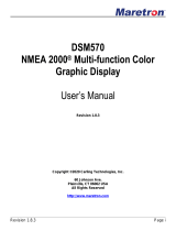
Figure 5
Default display configuration 1
Engine RPM (Display #1)
Boat Speed (Display #2)
Depth on NMEA#2A (Display #3)
Oil Pressure (“L” Display)
Engine Temperature (“R” Display)
second the display shows the data for display configuration #1 as
shown in figure 5. All 16 of the factory default display configurations
are shown in figures 5-20. Note that the two bar graphs can be
configured to display only a single arrow as shown in figure 6 or a
full bar graph as shown in figure 5. However, once selected, the same
type of bar graph is displayed for all display configurations. Figures
7 through 21 all use the full bar graph method.
Figure 4 - Current Display
Configuration
“R” Display
Display #2
Display #1
Display #3
“L” Display

Page 15
Figure 7
Default display configuration 3
Engine RPM
Boat Speed
Sea Water Temperature
Oil Pressure
Engine Temperature
Figure 6
Default display configuration 2
Engine RPM
Boat Speed
Fuel Remaining
Oil Pressure
Engine Temperature
Figure 8
Default display configuration 4
Depth (On NMEA input #2A)
Boat Speed
Engine RPM
Oil Pressure
Engine Temperature

Page 16
Figure 11
Default display configuration 7
Boat Speed
Depth (On NMEA input #2A)
Engine RPM
Oil Pressure
Engine Temperature
Figure 10
Default display configuration 6
Depth (On NMEA input #2A)
Boat Speed
Sea Water Temperature
Oil Pressure
Engine Temperature
Figure 9
Default display configuration 5
Depth (On NMEA#2A input)
Boat Speed
Fuel Remaining
Oil Pressure
Engine Temperature

Page 17
Figure 12
Default display configuration 8
Boat Speed
Depth (On NMEA input #2A)
Sea Water Temperature
Oil Pressure
Engine Temperature
Figure 13
Default display configuration 9
Boat Speed
Depth (On NMEA#2A input)
Fuel Remaining
Oil Pressure
Engine Temperature
Figure 14
Default display configuration 10
Engine RPM
Bearing to Waypoint (GPS On NMEA #4A)
Distance To Waypoint (GPS On NMEA #4B)
Oil Pressure
Engine Temperature

Page 18
Figure 17
Default display configuration 13
Depth (On NMEA input #2A)
Battery Bank #1 Volts
Time of Day
Trim Angle on Aux#1 Input
EGT Pyrometer (On NMEA #3A)
Figure 15
Default display configuration 11
Depth (On NMEA input #2A)
Bearing to Waypoint (GPS On NMEA #4A)
Distance To Waypoint (GPS On NMEA #4B)
Oil Pressure
Engine Temperature
Figure 16
Default display configuration 12
Boats Speed
Bearing to Waypoint (GPS On NMEA #4A)
Distance To Waypoint (GPS On NMEA #4B)
Oil Pressure
Engine Temperature

Page 19
Figure 18
Default display configuration 14
Boats Speed
Wind Speed (On NMEA #1A)
Wind Direction (On NMEA #1B)
None
Depth (ON NMEA#2A)
Figure 19
Default display configuration 15
Battery Bank #1 Volts
Battery Bank #2 Volts
Battery Bank #3 Volts
Fuel Remaining
Water Tank Level (On NMEA #2B)
Figure 20
Default display configuration 16
None
None
None
None
None

Page 20
Turning Alarms ON/OFF
To “arm” the alarms, press and hold the $ key 1/2 second. The Bell symbol
will be displayed when the alarms are “armed”. To disable the alarms press and
hold the % key for 1/2 second. Any press between 1/2 and 2 seconds will
work. A press of less than 1/2 second or longer than 2 seconds will be ignored.
Setting High and Low Alarm Values
To View and/or Set the High Alarm value for any of the five current digital dis-
plays and bar charts, press and hold the $ key for ten seconds (until you hear
a long beep). To View and/or Set the Low Alarm value for any of the displays
press and hold the % key for ten seconds. The alarm value, display identifier
(1, 2, 3, L or r) and the word “HiAL” or “LoAL” will be displayed as shown in
Figure 21. Quick press the & key to select the desired display identifier (1, 2,
3, L or r). Press and hold the % and $ keys to change the alarm value. Press
the & key for 1 second (until the long beep) to accept the new alarm value, save
it to memory and leave the Alarm Editor mode.
To prevent confusion, the High and Low alarm values are unique for each Data
Source (i.e. RPM or Fuel level, etc.). For example, if you change the high alarm
value for RPM in one display configuration, then the high alarm value for RPM
will automatically change for each display configuration where RPM is displayed.
Be sure to read the warnings about alarms in the Important Notes and
Figure 21 - Alarm Editor
Editing the Hi alarm
for display #3
/