Page is loading ...

FOX DA8 Plus • Setup Guide
This guide provides quick start instructions for an experienced installer to set up and operate the
Extron FOX DA8 Plus fiber optic distribution amplifier. See the drawing on the next page.
WARNING: This unit outputs continuous invisible light, which may be harmful to the eyes;
use with caution. For additional safety, plug the attached dust caps into the
optical transceivers when the fiber optic cable is unplugged.
Installation
Step 1 — Mounting
Turn off or disconnect the power sources to all equipment and mount the FOX DA8 Plus as desired.
Step 2 — Conguration
Set the rear panel DA configuration switch to configure the unit as either one 8-output DA, two 4-output DAs, or four 2-output DAs.
See the drawing below.
FOX DA8 Plus
100-240V 0.3A
OPTICAL OUTPUTS
A BCD
OUT IN
1
OUT IN
3
OUT IN
5
OUT IN
7
(1)1x8
(2)1x4
(4)1x2
50/60 Hz
RS-232
Tx Rx
OUT N/A
4
OUT N/A
6
OUT N/A
8
OUT N/A
2
FOX DA8 Plus
100-240V 0.3A
OPTICAL OUTPUTS
A B C D
OUTIN
1
OUTIN
3
OUTIN
5
OUT IN
7
(1)1x8
(2)1x4
(4)1x2
50/60 Hz
RS-232
Tx Rx
OUT N/A
4
OUT N/A
6
OUT N/A
8
OUT N/A
2
FOX DA8 Plus
100-240V 0.3A
OPTICAL OUTPUTS
ABCD
OUTIN
1
OUTIN
3
OUTIN
5
OUTIN
7
(1)1x8
(2)1x4
(4)1x2
50/60 Hz
RS-232
Tx Rx
OUTN/A
4
OUTN/A
6
OUTN/A
8
OUTN/A
2
Rx
Tx Tx Tx Tx TxTx Tx
Rx Rx Rx Rx Rx Rx Rx Rx Rx Rx Rx Rx Rx Rx Rx Rx Rx Rx Rx Rx Rx Rx Rx
CGroup: AGroup: ACDB
One 8-output DA Two 4-output DAs
(Groups A and C)
Four 2-output DAs
(Groups A through D)
(1)1x8
(2)1x4
(4)1x2
(1)1x8
(2)1x4
(4)1x2
(1)1x8
(2)1x4
(4)1x2
Step 3 — Optical Inputs
OPTICAL
2* 1
LINK
LINK
OPTICAL
1 2*
*
OPTIONAL FOR
RETURN DATA
LINK
LINK
Transmitter
Receiver
DA
3
4
A
OUT IN
1
Connect a fiber optic transmitter (or the maximum number of inputs as determined by the DA configuration switch
position in step 2) to the FOX DA8 Plus rear panel input connector.
NOTES: • Inputs 3, 5, and 7 (the right-hand connector on those transceiver blocks) are functional only when
selected as an input using the DA configuration switch.
• The right-hand connector for transceiver blocks 2, 4, 6, and 8 can never be functional.
• Singlemode and multimode devices are not interchangeable. Ensure that you connect transmitting and
receiving devices that are compatible with the FOX DA8 Plus.
• Ensure that you use the proper fiber cable for your system. Typically, singlemode fiber has a yellow jacket
and multimode cable has an orange or aqua jacket.
Step 4 — Optical Outputs
Connect up to eight fiber cables between the FOX DA Output LC connectors (the left-hand connector on each
transceiver block) and compatible receivers.
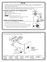
Step 5 — Remote Control Connections
Do not tin the wires!
Controlling
Device
Gnd ( )
Rx
Tx
Ground ( )
Receive (Rx)
Transmit (Tx)
Bidirectional
RS-232
Tx Rx
FunctionPin
TX
RX
Gnd
Transmit data
Receive data
Signal ground
z Connect a host device to the rear panel RS-232 port.
See the drawing at right to make the connection
z Connect a host device to the front panel Config(uration) port,
a mini USB port.
Step 6 — Power
Use a standard IEC power cord to connect the FOX DA8 Plus power connector
and a 100 VAC to 240 VAC, 50-60 Hz power source.

2
FOX DA8 Plus
100-240V 0.3A
50/60 Hz
OPTICAL OUTPUTS
A
OUT IN
1
OUT N/A
2
B
OUT IN
3
OUT N/A
4
C
OUT IN
5
OUT N/A
6
D
OUT IN
7
OUT N/A
8
(1)1x8
(2)1x4
(4)1x2
N15779
RS-232
Tx Rx
FOX 500 Tx
100-240V 0.3A
50/60 Hz
AUDIO INPUTS
INPUT LOOP THRU
RGB INPUT
R
G
B
H V
OR
L
R
RS-232
PASS THRU
Tx Rx NA
RS-232
CONTROL
ALARM
*
OPTIONAL FOR
RETURN DATA
LINK
LINK
Tx Rx
1 2
RGB
OPTICAL
1 2*
FOX 500 Rx
AUDIO OUTPUT
RGB OUTPUTS
R G B
H
V
L
R
RS-232
PASS THRU
Tx Rx NA
RS-232
CONTROL
ALARM
1
2*
*
OPTIONAL FOR
RETURN DATA
LINK
LINK
Tx Rx
1 2
RGB
100-240V 0.3A
50/60 Hz
OPTICAL
FOX 500 Rx
AUDIO OUTPUT
RGB OUTPUTS
R
G
B
H
V
L
R
RS-232
PASS THRU
Tx Rx NA
RS-232
CONTROL
ALARM
1
2*
*
OPTIONAL FOR
RETURN DATA
LINK
LINK
Tx Rx
1 2
RGB
100-240V 0.3A
50/60 Hz
OPTICAL
POWER
12V
3A MAX
OUTPUT
4/8
OHMS
INPUTS
L
R
L
R
REMOTE
VOL/MUTE
10V
50mA
L
MPA 152
R
C
US
LISTED
17TT
AUDIO/VIDEO
APPARATUS
CLASS 2 WIRING
DO NOT GROUND
OR SHORT
SPEAKER OUTPUTS!
Extron
FOX 500 DVI Rx
Fiber Optic Receiver
Extron
FOX 500 DVI
Fiber Optic Receiver
Projector
Projector
Flat Panel
Display
Flat Panel
Display
DVI Output
DVI Output
RGB Output
RGB Output
RGB Input
Extron
FOX 500 Tx
Fiber Optic
Transmitter
Extron
FOX DA8 Plus
Fiber Optic Distribution Amplifer
Audio Input
PC
Local
Monitor
Extron
FOX 500 Rx
Fiber Optic Receiver
Extron
FOX 500 Rx
Fiber Optic Receiver
Extron
MPA 152
Mini Power
Amplier
Extron
SI 26X
Two-way Ceiling
Speakers
Selected SIS Commands
The table below is a partial list of SIS commands the you can use to mute outputs and configure the input reclockers. For a complete
listing, see the FOX DA8 Plus User Guide. Run the commands from a PC connected to the RS-232 port or the Configuration (USB) port.
Command
ASCII Command
(Host to Unit)
Response
(Unit to Host)
Additional Information
Mute or unmute one output
X!
*
X@
B Vmt
X!
*
X@] X!
= output,
X@
= 0 (mute off) or 1 (mute on).
Show mute status of an output
X!
*B
X@] X!
= output,
X@
= 0 (mute off) or 1 (mute on).
Mute or unmute all outputs
X@
*B Vmt
X@] X@
= 0 (mute off) or 1 (mute on).
Set input reclocker mode
X#
*
X$
= Rte
X#
*
X$] X#
= 00 (all inputs), 01, 03, 05, or 07.
X$
= 00 (bypass), 01 (1.25 Gbps), 02 (2.125 Gbps), or 03 (4.25 Gbps).
Show reclocker mode
X#
=
X$] X#
and
X$
are the same as for “Set input reclocker mode” command.
] = Carriage return and line feed • = space
68-2145-50
Rev A
07 11
Extron USA - West
Headquarters
+800.633.9876
Inside USA/Canada
Only
+1.714.491.1500
+1.714.491.1517 FAX
Extron USA - East
+800.633.9876
Inside USA/Canada
Only
+1.919.863.1794
+1.919.863.1797 FAX
Extron Europe
+800.3987.6673
Inside Europe Only
+31.33.453.4040
+31.33.453.4050 FAX
Extron Asia
+800.7339.8766
Inside Asia Only
+65.6383.4400
+65.6383.4664 FAX
Extron Japan
+81.3.3511.7655
+81.3.3511.7656 FAX
Extron China
+400.883.1568
Inside China Only
+86.21.3760.1568
+86.21.3760.1566 FAX
Extron Middle East
+971.4.2991800
+971.4.2991880 FAX
© 2011 Extron Electronics. All rights reserved. www.extron.com
FOX DA8 Plus • Setup Guide (Continued)
/