Page is loading ...


• Installation, operation and maintenance are performed according to the instructions of this manual;
• Environmental conditions and supply voltage fall within the values indicated here below;

1.1 Models available ................................................................................................................................................................. 4
1.1.1 PJ32S............................................................................................................................................................................ 4
1.1.2 PJ32Y - PJ32X .............................................................................................................................................................. 4
1.1.3 PJ32C............................................................................................................................................................................ 4
1.2 Characteristics.................................................................................................................................................................... 5
2.1 Meaning of the inputs and outputs........................................................................................................................................ 6
2.2 Instrument and accessory codes........................................................................................................................................... 7
2.2.1 Codes for the instruments in individual packaging .............................................................................................................. 7
2.2.2 NTC and PTC probes..................................................................................................................................................... 8
2.2.3 Accessories .................................................................................................................................................................... 8
2.3 User interface, meaning of operating indicators and LED display............................................................................................. 9
2.3.1 Using the keypad............................................................................................................................................................ 9
3.1 Mechanical installation........................................................................................................................................................10
3.2 Electrical connections.........................................................................................................................................................10
3.2.1 Power supply ................................................................................................................................................................10
3.2.2 Special warnings ............................................................................................................................................................11
3.2.3 General warnings – installation and connection environments.............................................................................................11
3.2.4 Electrical connections, PJ32............................................................................................................................................13
3.3 Setting the main operating parameters..................................................................................................................................14
3.4 Table summarising the parameters to be checked before installation .......................................................................................15
4.1 The configuration parameters..............................................................................................................................................16
4.2 Classification of the parameters...........................................................................................................................................16
4.3 The password PS...............................................................................................................................................................16
4.4 / = temperature probe management parameters.....................................................................................................................16
4.5 r = temperature control parameters......................................................................................................................................17
4.6 c = compressor management parameters..............................................................................................................................18
4.7 d = defrost management parameters ....................................................................................................................................20
4.8 A = alarm management parameters......................................................................................................................................22
4.9 F = evaporator fan management parameters.........................................................................................................................25
4.10 H = other settings...............................................................................................................................................................27
6.1 Modifying the Set Point and differential...............................................................................................................................29
6.2 Accessing the parameters....................................................................................................................................................29
6.3 Modifying the parameters ...................................................................................................................................................30
6.4 Saving the new values assigned to the parameters and exiting.................................................................................................30
6.5 Exiting the procedure without modifying the parameters ........................................................................................................30
6.6 Parameters – summary table...............................................................................................................................................30
7.1 Anomalous or special operating conditions............................................................................................................................32
7.2 Description of the main signals and alarms ...........................................................................................................................32
7.3 Data error .........................................................................................................................................................................33
7.3.1 Loading the default parameters........................................................................................................................................33
7.4 Troubleshooting.................................................................................................................................................................34
8.1 Key for copying the parameters...........................................................................................................................................35
8.2 Serial adapter for RS485 network........................................................................................................................................36
8.2.1 General characteristics....................................................................................................................................................36
8.2.2 Installation.....................................................................................................................................................................37
8.2.3 Setting the operating parameters......................................................................................................................................37

8.2.4 Serial adapter parameters................................................................................................................................................37
8.3 Additional HACCP module.................................................................................................................................................39
8.3.1 General characteristics....................................................................................................................................................39
8.3.2 Installation.....................................................................................................................................................................39
8.3.3 Setting the main operating parameters..............................................................................................................................39
8.3.4 Parameters - description .................................................................................................................................................40
8.3.5 Parameters of the plug-in instrument................................................................................................................................40
8.3.6 HACCP module parameters............................................................................................................................................40
8.3.7 Parameters corresponding to the recording of the HA and HF alarms..................................................................................42
8.3.8 Operating mode and alarm signals....................................................................................................................................42
8.3.9 Cancelling the alarms......................................................................................................................................................43
9.1 Table summarising the characteristics of the relays used........................................................................................................45
9.2 Temperature/resistance values for the NTC thermistors.........................................................................................................45

Cod. +030221881 rel. 1.0 - 11/02/2000 3
The new plug-in family for refrigeration is made up of a new series of microprocessor-based electronic controls with LED
display, designed for the management of display case and showcase refrigeration units.
A range of models is available, providing the best solution for all applications, at the most competitive price.
The plug-in family builds on the experience and success of the previous product ranges, such as the IR32 and IR32E, with the aim
of offering an increasingly simple and economical product, without relinquishing on the performance required by the refrigeration
manufacturer.
The structure of the parameters and the operating logic has remained from the IR32E range, a number of functions have been
simplified, and extra performance has been added. The main characteristics are:
• external RS485 serial interface, optionally connected to the instrument;
• display in degrees (centigrade or Fahrenheit), using display with two digits and minus sign;
• complete range with models featuring 1, 2, 3 relays;
• ergonomic three-button keypad.
Furthermore, new functions and characteristics have been introduced:
• probe inputs for NTC or PTC (different codes);
• display of operating status (cooling - defrost - alarm), using a clearly visible and easily recognisable signal, thanks to the three
buttons with back-lighting;
• highly-efficient red LED display;
• innovative system for fastening the instrument from the front panel, using two screws;
• front frames in various colours, customised upon request;
• external options available, such as: HACCP module and optically-isolated RS485 serial module;
• quick programming of the control, using hardware key, even when the instrument is not powered;
• possibility to modify the list of parameters, selecting each parameter as a frequently-used or password-protected parameter;
• electrical connections using removable (screw or crimped) or fixed screw connectors;
• power thermostat version with 12A resistive relay;
• complete range with power transformer for the 115-230Vac versions.

Cod. +030221881 rel. 1.0 - 11/02/2000 4
The various models are differentiated according to the following functions and performance:
• operating mode and number of inputs and outputs for versions S, Y, X and C;
• complete versions (hereafter: ) with serial connection, status LED, fastening from front panel, removable terminals;
• compact versions (hereafter: ) with fixed terminals and fastening only using rear bracket, and without serial connection;
• the power supply can be one of the following: 230Vac, 115Vac or 12Vac/Vdc;
• the field of measurement for all models is from -50 to +90 °C (-50 ÷127 °F), with resistive NTC probe;
• a PTC probe is available with the same field of measurement, for one model only (PJ32S );
• digital input from free contact: in models where featured it is an alternative to the second probe;
• relay outputs: available with three different current ratings, 5A, 8A and 12A (for resistive load);
This represents the ideal solution for the management of static refrigeration units (that is, without fan on the evaporator), operating
at normal temperature (above 0ºC). This instrument, in fact, performs the functions of thermometer, displaying the temperature of
the unit, and electronic thermostat, activating the compressor (or the electrovalve in the case of multiplexed units) so as to maintain
the required temperature. Furthermore, it handles automatic defrost using the forced shut-down of the compressor, and safety
functions through management of the time settings.
• All the S models use just one probe for the control functions (AMB. T.), and feature a changeover relay contact for the control
of the actuator (COMPRESSOR).
• In some models (PJ32S00 or S0P) a second probe can be connected to display the product storage temperature; this probe does
not affect control.
• There is a model (PJ32S20) with a digital input and two relay outputs: actuator control and output alarm with changeover
contact.
• The models (PJ32S0P and S1P) use a 12A resistive relay with changeover contact. In all the other models the relay is 8A
resistive;
• There are a significant number of versions, both and , with 230V, 115V and also 12V power supply.
These are designed for the management of static units operating at low temperature (that is, below 0ºC), which require 'active'
defrost using electrical heating elements or the injection of hot gas. The PJ32Y or X, in fact, as well as working as a thermometer
and a thermostat like the S model, also manages the defrost actuator. The frequency and duration of the defrost can be set. The end
defrost can occur according to the temperature reached (connecting a probe to the evaporator) or by time.
• The Y models feature two probe inputs, for control (AMB. T.) and for defrost (DEF. T.).
• The X models, on the other hand, feature just one probe and a digital input; for these models, timed defrost is compulsory.
• There are two relay outputs for the control of the actuator (COMPRESSOR) and for DEFROST control, with changeover
contacts, the relays used are 8A resistive.
• Almost all models feature removable terminals ( ), with 230 or 115V power supply. There is just one Y model ( ) with
12V power supply.
These represent the most complete solution for ventilated units operating at low temperature. In these models, there are three
relays, providing complete control of the compressor, fan and defrost management functions. The three 8, 5 and 5A resistive relays
have been built into a very compact case in the versions which also feature the 230V or 115V power transformer, and without
compromising the performance or the reliability of the product.
• There are two probe inputs for control (AMB. T.) and for defrost (DEF. T.).
• There are three outputs: the 8A resistive compressor relay, defrost, and 5A resistive for the fans.
• All versions have removable terminals ( ) and 115Vac and 230Vac power supply.

Cod. +030221881 rel. 1.0 - 11/02/2000 5
The plug-in can be powered at: 230Vac or 115Vac using an internal transformer, or at 12Vac/Vdc without internal transformer.
The LED signals are clearly visible, thanks to the back-lighting of the three buttons. The front panel frame can be customised both
in terms of colour and indications.
The temperature and the parameter settings are displayed by . For the temperature values, the field of
display is from -50 to + 127 degrees centigrade or Fahrenheit. For the parameters, the field of display can be from -99 to +199, or
from -127 to +127.
The controls with one relay only can be fitted as standard with a buzzer for signalling alarms.
Functions are:
• the activation of the compressor with programmable timers in the event of control probe fault.
• continuous cycle, which forces the activation of the compressor for the programmable time.
The digital input, when present, can be used to enable/disable/end the defrost, and to manage serious alarms which require the
immediate (e.g. high pressure) or delayed (e.g. low pressure) shut-down of the unit.
The economical versions ( ) maintain the traditional fixed terminals, while the complete versions ( ) use removable
terminals. The latter significantly simplify the installation and maintenance of the machine.
There are, according to the model, up to three relays for the control of , , and . When more than one
relay is fitted, the common of all the relays is connected and is available on just one terminal.
The alarm relay output, when present, can be set using a parameter to be normally activated or normally deactivated.
The keypad can be disabled to avoid tampering by unauthorised persons. For each parameter, furthermore, the level of possible
modification, with or without PASSWORD, can be set.
The versions feature serial connection, with the following external options:
• parameter copy key: allows the parameters to be duplicated and configured;
• HACCP module, used to record temperatures and alarms;
• RS485 serial adapter module, for connection to a supervisor.
In the models with two probes, the measurement of the second probe can be displayed instead of the first (control probe). This
function can be used to display the product storage temperature; the defrost mode, in this case, is only by time.
The fastening method used for the economical models ( ) uses a rear-panel fastening bracket, while all the other versions ( )
also feature the possibility of fastening , using two screws.
The plug-in series conforms to EU standards on electromagnetic compatibility:
• for appliances for domestic use EN55014-2 and EN55014-1;
• for residential, commercial and light industrial environments EN50082-1 and EN50081-1
• for industrial environments EN50082-2 and EN50082-1.
• Regarding safety, it conforms to standards EN60730-1 and EN60730-2-9.
The CE mark confirms the quality and the safety of the plug-in series, guaranteed by the Carel ISO 9001 certified design
and production system.

Cod. +030221881 rel. 1.0 - 11/02/2000 6
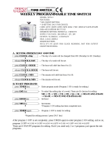
The instruments in the PJ32* series are temperature controls used to manage refrigeration units (showcases and display cases). An
application diagram is shown in the
figure; also indicated are the possible
accessories and expansion modules, as
well as the connections for the inputs and
outputs:
1. instrument;
2. plug-in frame;
3. temperature probes;
4. power transformer (according to the
models);
5. RS485 serial adapter module;
6. HACCP module;
7. parameter programming key.
This manual describes the characteristics
of the instrument, and only briefly
mentions the accessories and expansion
modules.
The connection of the RS485 or HACCP
expansion modules is mutually
exclusive.
(numbering of terminals, with reference to Fig. 2.1)
terminals 8 and 9; the value of the power supply can be 230Vac, 115Vac or 12Vac/Vdc. The effective value is
indicated on the connection label
terminals 5 and 6 are for the ambient temperature probe (control)
terminals 6 and 7 are for the defrost temperature probe (defrost), when featured
according to the code, connection is for standard Carel NTC or PTC probes
terminals 6 and 7 are for the digital input from free contact, when featured
the group of terminals numbered 1, 2, 3, 4 are for the connection of the relay outputs.
The assignment of the outputs can change according to the code , the effective assignment is indicated on the
connection label.
- For instrument codes with one relay only, the changeover contact is available for compressor control, using
terminals 1, 2, 3.
- For instrument codes with two relays, the changeover contact is available for defrost control, on terminals 1,
2, 3, and the closing contact for the compressor relay, on terminals 3 and 4. Terminal 3 is common for the two
relays, thus the current at the terminal will be the sum of the two.
- For instrument codes with three relays, terminal 1 is used for the compressor control, terminal 3 for fan
control, terminal 4 for defrost control and terminal 2 is the common of all three relays. The current at terminal
two will be the sum of the three outputs.
the four-pin connector is for connection to the RS485 serial and HACCP adapters, and for connection of the
parameter copy key. This connection is not present on the models
Power
230Vac
Power
230Vac
Power
230Vac
115Vac

Cod. +030221881 rel. 1.0 - 11/02/2000 7
The definition of the instrument codes is based on two categories: one for the simpler and more economical versions ( ), and
one for the versions complete with all functions ( ). The main differences between the two versions are that the following are
present only in the versions:
• removable terminals in the place of fixed terminals;
• fastening from front panel using screws;
• serial connector present, with the possibility to connect expansion modules and to the key.
the options indicated all freely modular, and so to avoid incompatibility, product codes have been defined
which cover the needs of the market. Customised versions can only be produced if they are compatible with the internal limits of
the instruments and according to adequate quantities and the kit requirements.
The front panel frame is supplied in grey (standard for the single instrument), it can be customised in terms of colour and text, and
can thus be ordered separately or in a kit.
PJ32S 12Vac/Vdc - NTC -no options- screw terminals relay 8A SPDT PJ32S0EL00
PJ32S 230Vac - NTC -no options- screw term. relay 8A SPDT PJ32S0E000
PJ32S 110Vac - NTC -no options- screw term. relay 8A SPDT PJ32S0E100
PJ32S 230Vac - PTC -no options- screw term. relay 8A SPDT PJ32S6E000
PJ32S 230Vac - 1(2)NTC - removable terminals relay 8A SPDT (*) PJ32S00000
PJ32S 110Vac - 1(2)NTC - removable terminals relay 8A SPDT (*) PJ32S00100
PJ32S 230Vac - 2 NTC - removable terminals-16A SPDT - buzzer (*) PJ32S0P000
PJ32S 230Vac - 1 NTC - removable terminals-16A SPDT – dig. input - buzzer PJ32S1P000
PJ32S 110Vac - 2 NTC - removable terminals-16A SPDT - buzzer (*) PJ32S0P100
PJ32S 110Vac - 1 NTC - removable terminals-16A SPDT – dig. input - buzzer PJ32S1P100
(*) the S models with two probes, PJ32S00* and PJ32S0P*, have been designed only to use the second probe for the measurement
and display of the food storage temperature (Food Probe). To manage the second probe these models are in reality programmed as
Y models, with all the corresponding parameters, yet without the defrost relay; it is clear that they must be set so as not to use the
defrost function or, if necessary, timed defrost only ( =2 for timed defrost, =0 for no defrost or >0 for cyclical defrost).
PJ32S 230Vac - NTC - removable terminals - comp. relay(8A NO) + alarm (8A SPDT) (**) PJ32S20000
PJ32S 110Vac - NTC - removable terminals - comp. relay(8A NO) + alarm (8A SPDT) (**) PJ32S20100
(**) the S models with alarm relay, PJ32S20*, to use the function for programming the status of the alarm relay using parameter
, are programmed as X models; as they do not have the defrost relay, they must be programmed so as not to use the defrost
function or, if necessary, timed defrost only (see (*) Tab. 2.2.2).
PJ32Y 12Vac/Vdc - 2 NTC - comp. relay (NO) + defrost (SPDT) PJ32Y0EL00
PJ32Y 230Vac – 2 NTC probes - comp. relay (NO) + defrost (SPDT) PJ32Y00000
PJ32X 230Vac - 1 NTC probe - 1 digital input - comp. relay (NO) + defrost (SPDT) PJ32X10000
PJ32Y 110Vac - 2 NTC probes - comp. relay (NO) + defrost (SPDT) PJ32Y00100
PJ32X 110Vac - 1 NTC probe - 1 digital input - comp. relay (NO) + defrost (SPDT) PJ32X10100
PJ32C 230Vac - 2 NTC - comp. relay (8A NO) + defrost (5A NO) + fan (5A NO) PJ32C00000
PJ32C 110Vac - 2 NTC - comp. relay (8A NO) + defrost (5A NO) + fan (5A NO) PJ32C00100
the versions of instrument with display colours other than red are currently not available.

Cod. +030221881 rel. 1.0 - 11/02/2000 8
All PTC and NTC probes conforming to the Carel standard can be used, with resistance values of 985 Ω at 25°C, for PTC, and of
10 kΩ for NTC. Below are some codes of the more common versions.
°
NTC probe, 6x15 mm bulb, plastic, -50 ÷ 50 IP67 NTC0**HP00
NTC probe, 6x40 mm bulb, metal -50 ÷ 100 IP67 NTC0**W*00
PTC probe, 6x40 mm bulb, metal, 1.5m long -50 ÷ 100 IP67 PTC015W000
NTC probe, wall-mounting -10 ÷ 70 IP30 ASWT011000
NTC probe, duct -10 ÷ 70 IP40 ASDT011000
(
only for instruments with 12Vac power supply).
TRA 12: 3 VA, 240/12Vac without fuse on the primary TRA12VDE00
TRA 12: 3 VA, 240/12Vac with fuse on the primary TRA12VDE01
optically-isolated RS485 serial module PJOPZ48500
additional module for HACCP PJOPZHACP0
programming key for plug-in PJOPZKEY00
pack of 30 frames, GREY (STANDARD) PJOPZFG000
pack of 30 frames, BLUE PJOPZFB000
pack of 30 frames, RED PJOPZFR000
pack of 30 frames, WHITE PJOPZFW000
pack of 30 frames, YELLOW PJOPZFY000
pack of 30 frames, ALUM. METAL PJOPZFMA00
pack of 30 frames, BLUE METAL PJOPZFMB00
pack of 30 frames, GOLD METAL PJOPZFMG00
pack of 30 frames, STEEL METAL PJOPZFMS00
if requested by the customer and the quantity supplied is sufficient, the plug-in instruments can be
packaged in multiples of 10. The kit also allows the instrument the ordered together with the options and accessories
used by customer in the application. Customised programming of the parameters can also be requested.
The kit codes are defined according to customer request.
• the kits are packs of 10 instruments with the corresponding accessories; orders must indicate the total quantity of instruments
required (not the number of packs); the quantity ordered must be a multiple of 10, as partial packs are not supplied;
• the quantity of each component in the kit is 10 units, except for the instruction sheet, which can be ordered in single quantities;

Cod. +030221881 rel. 1.0 - 11/02/2000 9
Fig. 2.3.1 shows the front panel of the plug-in: display and buttons. On the front
panel of the instrument there is a three-digit display (ref. 4 in the figure 2.3.1), and
three LEDs back-lighting the buttons (refs. 1, 2 and 3 in Fig. 2.3.1).
These indicate:
this LED indicates the of the actuator controlled, (normally a
compressor); the button is back-lit by a green LED and is available only on the models.
The status of the LED can be the following, to indicate:
request pending for compressor activation
continuous cycle on
present only on the models, the button is back-lit by a red LED.
present only on the models, the button is back-lit by a green LED. The status of the LED can be:
defrost in progress
request pending for defrost
THE LED DISPLAY
• in normal operation: value measured by the ambient probe or the second probe;
• when setting parameters: code of the parameter or the associated value;
• during an alarm event: flashing code of the alarm detected, alternating with the temperature value.
The temperature measured by the probe is displayed with resolution to a degree (ºC or ºF).
The display range for the temperature is: -50 ÷ 90 ºC (or -50 ÷ 127 ºF).
For the parameters, the values can vary from -99 to +199 and in some cases from -127 to +127. The unused segments of the left-
most digit are normally always off; expansion modules (Serial 485 and HACCP) can be used to signal states or parameter
programming modes. For a complete description please refer to the expansion module manual.
Three buttons (5, 6 and 7 in Fig.2.3.1) are used to perform the activation and deactivation of the instrument’s operating states and
set the parameters.
The use of the buttons can be divided into two different situations: one in of normal operation, and the other to modify the
parameters. For each button, the following are the possible actions associated with both possibilities.
In and if pressed for more than 5 seconds:
• activates/deactivates continuous cycle (compressor).
In mode:
• moves from one parameter to the next;
• increases the value of the parameter.
:
• silences the audible alarm (only if featured);
• displays and/or sets the ;
• if pressed for more than 5 seconds not during an alarm: accesses the menu for setting type ‘F’ parameters
(frequent);
• if pressed when turning on the instrument, together with the button, activates the parameter RESET
procedure.
In mode:
• displays the value of the selected parameter /exits the display;
• if pressed for more than 5 seconds in modify parameter mode, saves the changes.
In :
• if pressed for more than 5 seconds: starts a manual defrost, if enabled.
In mode:
• moves from one parameter to the previous;
• decreases the value of the parameter.

Cod. +030221881 rel. 1.0 - 11/02/2000 10
The installation operations for the plug-in controls can be grouped as follows:
1. mechanical installation;
2. electrical connections: probes, power supply and actuators;
3. setting of the operating parameters.
1. Insert the instrument in the previously created hole as per the drilling template, 71x29 mm;
2. for mounting using the bracket (for all versions): lock the instrument onto the panel, by sliding the bracket;
3. for mounting using screws from the front panel (only for the versions): rest the instrument on the front panel and, using the
screwdriver tighten the two screws, making sure the two teeth are properly clicked in. The following describes the procedure
in detail. The thickness of the fastening panel must not exceed 3 mm;
3.1 remove the front panel frame and check that the two attachment teeth are in their slot (they must not protrude from the
dimensions of the drilling template). If necessary, unscrew the two screws, applying pressure. Do not unscrew too
much, the screw must not be raised from the front panel;
3.2 connect all the cables to the corresponding terminals or insert the pre-wired removable terminals onto the
corresponding connectors;
3.3 insert the instrument in the hole in the panel, placing the connected cables inside, and hold it in position by pressing in
the centre of the front panel; using the screwdriver , tighten the lower screw 90°, the tooth must come out of its slot
and click onto the panel, then tighten up until the front panel is secure;
3.4 repeat the same operation for the upper screw;
3.5 if the tooth does not click onto the panel (max. thickness 3.0 mm), unscrew the screw, applying pressure at the same
time with the screwdriver so that the tooth moves back. As mentioned in point 1, do not unscrew too much, the head of
the screw must not be raised from the surface of the front panel;
3.6 the two screws must be tightened with the same pressure, so as to not leave one corner higher than the other. DO NOT
tighten excessively, ;
3.7 apply the front panel frame.
4. If having to remove the instrument, proceed as follows:
4.1 unclip the front panel frame;
4.2 unscrew the lower screw, at the moment the front panel leaves the panel keep pressure on the screw and unscrew a
further 90° to make the tooth go back into its slot;
4.3 repeat for the upper screw;
4.4 remove the instrument from panel, keeping it horizontal;
the screwdriver which should be used is the Pozidriv 1 (PZD1) Phillips head screwdriver.
The instruments in the PJ32 series feature different terminals for the connections:
• the Eco versions use the traditional fixed screw terminals;
• the Top versions, on the other hand, feature removable terminals with two types of cable connection blocks: screw, or by
crimping.
The versions with removable terminals offer considerably simplified connection of the instrument, both for installation and
maintenance. Furthermore, connection errors are avoided, as the three connection blocks have a different number of pins.
The plug-in instruments are connected to the power supply using terminals 8 and 9 in the Eco versions, or with the two-way
removable block to be inserted in the terminals 8 and 9 for the Top versions.
The voltage supplied to these terminals must correspond, within the tolerance indicated, to the value on the instrument’s connection
label. The values are 230Vac, 115Vac and 12Vac/Vdc, according to the code.
The electrical insulation featured in the instrument, for the versions with mains power supply (230Vac and 115Vac), corresponds
to reinforced insulation. The versions with 12Vac/Vdc power supply do not feature insulation.
To guarantee correct operation during voltage drops, all the plug-in instruments feature low power operation: below a certain
threshold the current supplied to the display is gradually reduced, up to the total switching off of the display and LEDs. All the
other functions are guaranteed within the maximum allowed voltage drop limits; in particular, the status of the relay is maintained.
On return of the normal power supply conditions, the display and the LED are reset.

Cod. +030221881 rel. 1.0 - 11/02/2000 11
For the direct connection of the instruments and the layout and checking of the wiring, the following warnings must be carefully
read and the diagrams adhered to; errors in connection can cause danger to the safety of the user and damage the instruments and
connected components. Also remember that the units must be fitted with all the electromechanical safety devices required to ensure
correct operation and the complete safety of the user.
• , a safety transformer is required (Carel code TRA12VDE01 or TRA12VDE00) to guarantee the double
insulation between the power supply and the low voltage electronics inside. If required, the protective fuse placed in series with
the primary (32 mAT, for code TRA12VDE00) is indispensable. The connection between the transformer and the instrument must
be as short as possible;
• , a suitably rated adapting transformer must be used: double insulation between
primary and secondary, and suitable surge features on the primary (2000V for applications in industrial environments).
• the instrument can be powered directly, evaluating the following conditions. The power line must not be connected
to the actuators and must not be near other connections which may cause high intensity disturbance. In case of doubt, and to
guarantee conformity to electromagnetic immunity standards, an insulating transformer, with the characteristics described in the
previous point, is recommended.
If more than one control with a 12Vac power supply is connected to the same transformer, the polarity of the wiring must be
checked, in the sense that each terminal of the transformer must be connected to the same terminal of all the controls. In this case,
conformity to the EMI standards must be evaluated by the manufacturer/installer.
Avoid mounting the boards in environments with the following characteristics:
• relative humidity over 90% or presence of condensation;
• heavy vibrations or knocks;
• exposure to continuous jets of water;
• exposure to aggressive and polluting atmospheric agents (e.g.: sulphur and ammonia gases, saline mist, smoke) which may
cause corrosion and/or oxidation;
• high magnetic and/or radio-frequency interference (thus avoid installation near transmitting antennae);
• exposure to direct sunlight and atmospheric agents in general;
• large and rapid fluctuations in ambient temperature;
• environments where explosives or mixes of inflammable gases are present;
• exposure to dust (formation of corrosive patina with possible oxidation and reduction of insulation);
These warnings must be for connection:
• electrical power supply other than that prescribed may seriously damage the system;
• use cable ends that are suitable for the terminals. Loosen each screw and insert the cable end, then tighten the screws. On
completing the operation, tug the cables lightly to check they are sufficiently tight;
• separate the probe signal and digital input cables from inductive loads and power cables as much as possible, to avoid any electromagnetic
disturbance. Do not
install the probe cables in the immediate vicinity of power devices (contactors, thermo-magnetic devices or other);
• reduce the length of the sensor cables as much as possible, and avoid spirals around power devices. The probes must be
connected using shielded cables (minimum cross-section for each lead: 0.5 mm
2
);
• the probes can be installed up to a maximum distance of 100m from the control. To extend the distance of the probes, use
cables with a minimum cross-section of 1 mm², shielded where possible. In this case, the shield must be connected to the
common of the probe. Do not earth the other end of the shield (the sensor end);
• only use IP67 probes as end defrost probes; place the probes with the vertical bulb upwards, so as to assist the drainage of any
condensation. Remember that the thermistor temperature probes (NTC or PTC) have no polarity, so the order of connection of
the ends is not important;
• avoid direct contact with the internal electronic components.
Wiring diagrams for multiple units, wiring examples for the serial connection of the instruments:
MAIN: mains power supply, 230 or 115Vac;

Cod. +030221881 rel. 1.0 - 11/02/2000 12
Serial: serial connection to the supervisor system;
TRF: 3VA transformer.
: the diagrams show the serial connection including the RS485 serial interface adapter (see options) which is external
to the instrument and must be powered separately. Versions with 115 and 230 Vac power supply are also available for the serial
adapter. For reasons of EMI compatibility, a 3VA transformer (TRF in fig. 3.4.2.1) (see options) is required for each PJ32
instrument with 12Vac power supply.
* only on last module

Cod. +030221881 rel. 1.0 - 11/02/2000 13
• before connecting the power, check the correct value of the power supply as shown on the label of the instrument;
• all models use NTC probes, except for the PJ32S6E0*, which uses PTC probes;
• for models S200 and S201 the alarm relay can be set as normally energised or normally de-energised, using parameter .

Cod. +030221881 rel. 1.0 - 11/02/2000 14
The plug-in series instruments are supplied ready to use. They are in fact programmed in the factory (default settings) to respond to
the more common requirements. The programming is performed by assigning all the parameters the more frequently required value;
the table below lists the parameters and the corresponding default value.
(**)
ambient probe calibration -127 127 °C/°F x 0,1
measurement stability (probe delay and range limit), 1 = fast 1 15
selection of probe to display (0 = ambient, 1 = defrost) 0 1
selection °C/°F (0=°C) 0 1
control differential (hysteresis) 0 19 °C/°F
minimum set allowed to the user -50 127 °C/°F
maximum set allowed to the user -50 127 °C/°F
enable alarm (1=enable) 0 1
set automatic variation of the Set Point for night operation -20 20 °C/°F
compressor start delay at instrument on 0 15 min
minimum time between 2 successive starts of the compressor 0 15 min
minimum compressor off time 0 15 min
minimum compressor on time 0 15 min
Duty Cycle safety relay ON time 0 100 min
continuous cycle duration 0 15 hours
alarm bypass time after continuous cycle 0 15 hours
type of defrost (0=heat el., 1=gas, 2=heat. el. time, 3=gas time) 0 3
interval between two defrosts 0 199 hours/min
end defrost temperature -50 127 °C/°F
maximum defrost duration or effective duration for =2 or =3 1 199 min/s
defrosting at instrument on (1=yes) 0 1
defrost delay 0 199 min
display off during defrost (1=yes) 0 1
post-defrost dripping time 0 15 min
alarm bypass time after defrosting 0 15 hours
defrost priority over minimum compressor times (1=yes) 0 1
time basis (0 =hours/min, 1=min/s) 0 1
alarm/fan differential 0 19 °C/°F
shift low temperature alarm threshold 0 127 °C/°F
shift high temperature alarm threshold 0 127 °C/°F
temperature alarm delay 0 199 min
digital input configuration 0 4
alarm input detection delay 0 199 min
fan operating mode 0 1
fan on temperature -50 127 °C/°F
fans off with compressor off (1=yes) 0 1
fans off during defrost (1=yes) 0 1
fan time-out during post dripping 0 15 min
serial address 0 199
IR34S: enable defrosting, IR34C: multifunction relay function 0 1
disable keypad, 0=disabled 0 1
disable buzzer 0 1
control Set Point -50 127 °C/°F
(**) (hereafter in the tables).
To achieve the maximum performance from the controls, or in the case of special needs, the values of the operating parameters can
be modified. The following notes describe the factory settings and the parameters which are more frequently modified (Set Point,
differential, etc.). Furthermore, for convenience, all parameters which should be checked before operating the unit are indicated.

Cod. +030221881 rel. 1.0 - 11/02/2000 15
Based on the factory settings, the functions are the following:
• : configured as a thermostat, with operation in degrees centigrade, at 4ºC and differential of 2ºC. The
DEFROST operation is enabled by time at 8 hour cycles lasting 30 minutes (compressor stop only). The high and low temperature
alarms are disabled. In the case of operation in continuous cycle, the duration is 4 hours and the temperature alarm is bypassed for
2 hours from the end of the cycle.
• : have the same settings as the PJ32S. Furthermore, these are programmed to manage defrosting using electrical
elements, with operation based on time for the X version, and with the second probe for the Y model. The display of the
temperature during defrosting remains on the last value acquired before the start of the defrost. There is an evaporator dripping
time of two minutes after the defrost, and the high temperature alarm is bypassed for one hour from end defrost.
• : on top of the functions of the IR32Y, these units are set to manage the evaporator fans, which are stopped when the
compressor is off and during defrosting. Furthermore, a one minute pause is set for the fans after dripping, to allow the evaporator
to return to operating temperature before starting forced ventilation. In the IR32C, the defrost is stopped when the probe on the
evaporator measures 4ºC (defrost by temperature).
If many of the instrument’s parameters need to be modified during installation, it may be useful to set the complete configuration of
one instrument, and then copy it using the KEY accessory; in this case the operation can be performed in just a few seconds, with a
complete copy of all the parameters.
control differential F 0 +19 °C/°F 2
control Set Point -50 127 °C+/°F 4
type of defrost (0=heating element, 1=hot gas, 2=heating element
by time, 3=hot gas by time)
C 0 1 flag 0 (*)
interval between defrosts F 0 199 h 8
end defrost temperature Set Point F -50 +127 °C/°F 4
temperature alarm delay F 0 +199 min 0
shift low temperature alarm threshold F 0 +127 °C/°F 0
shift high temperature alarm threshold F 0 +127 °C/°F 0
enable defrosting mod. S and selection of multifunction relay
function (alarm)
C 0 1 flag 1
(*) :
• for all models where the second probe is not used or used for the display of the product temperature, or for the models with
the alarm relay, parameter must be set for timed defrost, in this way, any alarms from the second probe are not signalled. To
stop the running of the defrost cycles, parameter must also be set to 0;
•
the S models with two probes (codes PJ32S00 and S0P) have been designed to use the second probe for measuring and
displaying the food storage temperature (Food Probe). To manage the second probe, these models are in fact programmed as Y
models, with all the corresponding parameters, but do not have the defrost relay; it is clear that they must be set so as defrosting is
not enabled, or, if necessary, only timed defrost with compressor off;
•
the S models with alarm relay, PJ32S20*, to use the function of programming the status of the alarm relay by parameter are
set as X models; as they don’t have the defrost relay they must be programmed so as defrosting is not enabled, or, if necessary,
only timed defrost with compressor off ( =0 or >0 for cyclical defrost).

Cod. +030221881 rel. 1.0 - 11/02/2000 16
The parameters can be classified in two groups for setting:
• frequent parameters (indicated by type F in the following tables);
• configuration parameters (type C), whose selection is ‘password’ protected to prevent unwanted tampering.
The assigning of the parameters to groups F and C can also be programmed, but only via serial access using the key or a
supervisory system.
Following is a description of each parameter, indicating the versions it is available in and the possible values.
Furthermore, the (def.) is listed, that is the value assigned to the parameter in the factory.
The parameters, as well as being divided by type, are also grouped in logical categories identified by the fist letters of the
parameters themselves. Following is a list of the existing categories, with the meaning and identifying letters.
indicates the password, this must be entered to access the configuration parameters (C)
temperature probe management parameters
temperature control parameters
compressor management parameters
defrost management parameters
alarm management parameters
evaporator fan management parameters
general configuration parameters
This is deliberately included to complicate access to type C parameters, so as to prevent accidental or unauthorised modifications.
Type C parameters are in fact those which modify the configuration of the control. Once entered into the configuration parameters
section using the password, the control also allows, for convenience, type F parameters to be modified.
When displaying the type F parameters, type C parameters are accessed as follows:
1. select the password parameter ;
2. enter and confirm the value 22, the correct password;
3. all the parameters, F and C, can now be selected on the display.
ambient probe calibration x10 (tenths of a degree) F -127 +127 °C/°F 0.0
measurement stability C 1 15 - 4
display control / food storage probe F 0 1 - 0
display in °C/°F (0=°C, 1=°F) C 0 1 flag 0
This parameter allows the temperature shown on the display to be corrected. The value assigned to this parameter is in fact added
to (positive value) or subtracted from (negative value) the temperature measured by the probe. For example, if the temperature
displayed needs to be decreased by 2.3 degrees, set =-23.
The Offset can range from -127 to +127, with a variation in the reading between -12.7 and +12.7 (°C/°F). The parameter does not
act on the defrost probe (in all the models with two probes). Def.: 0.0 (no Offset to probe reading).
Available on all models.
Defines the coefficient used to establish the temperature measurement. Low values assigned to this parameter offer the prompt
response of the sensor to variations in temperature; the reading is however more sensitive to disturbance. High values slow down
the response but guarantee greater immunity to disturbance, that is a more stable and more precise reading. The setting is also used
also for the second probe, if present. Value from 1 to 15. Def.: 4.
Available on all models.
/