Page is loading ...

ORION® Water Endpoints
ORI-UM-00025-EN-19 (February 2019)
Installation Manual
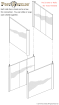
Image shown represents ORION Cellular LTE endpoint installed, as per instructions,
through non-metal pit lid

ORION® Water Endpoints
ORI-UM-00025-EN-19
CONTENTS
SCOPE OF THIS MANUAL . . . . . . . . . . . . . . . . . . . . . . . . . . . . . . . . . . . . . . . . . . . . . . . . . . . . . . . . . . . . . . . . . . . . . . . . 3
PRODUCT UNPACKING AND INSPECTION . . . . . . . . . . . . . . . . . . . . . . . . . . . . . . . . . . . . . . . . . . . . . . . . . . . . . . . . . . . . . 3
LICENSE REQUIREMENTS . . . . . . . . . . . . . . . . . . . . . . . . . . . . . . . . . . . . . . . . . . . . . . . . . . . . . . . . . . . . . . . . . . . . . . . . 3
IDENTIFICATION . . . . . . . . . . . . . . . . . . . . . . . . . . . . . . . . . . . . . . . . . . . . . . . . . . . . . . . . . . . . . . . . . . . . . . . . . . . . . . 4
Endpoints
. . . . . . . . . . . . . . . . . . . . . . . . . . . . . . . . . . . . . . . . . . . . . . . . . . . . . . . . . . . . . . . . . . . . . . . . . . . . . . . . 4
Endpoint Dimensions
. . . . . . . . . . . . . . . . . . . . . . . . . . . . . . . . . . . . . . . . . . . . . . . . . . . . . . . . . . . . . . . . . . . . . . . . 4
Encoders/Register
. . . . . . . . . . . . . . . . . . . . . . . . . . . . . . . . . . . . . . . . . . . . . . . . . . . . . . . . . . . . . . . . . . . . . . . . . . . 4
ORION CELLULAR LTEM, LTE ENDPOINTS . . . . . . . . . . . . . . . . . . . . . . . . . . . . . . . . . . . . . . . . . . . . . . . . . . . . . . . . . . . . . 5
ORION FIXED NETWORK AND MIGRATABLE ENDPOINTS . . . . . . . . . . . . . . . . . . . . . . . . . . . . . . . . . . . . . . . . . . . . . . . . . . . 7
ORION CLASSIC ENDPOINTS . . . . . . . . . . . . . . . . . . . . . . . . . . . . . . . . . . . . . . . . . . . . . . . . . . . . . . . . . . . . . . . . . . . . . . 9
ACTIVATING ENDPOINTS . . . . . . . . . . . . . . . . . . . . . . . . . . . . . . . . . . . . . . . . . . . . . . . . . . . . . . . . . . . . . . . . . . . . . . . .11
CHANGING REGISTRATION FOR AN EXISTING ENDPOINT ASSEMBLY . . . . . . . . . . . . . . . . . . . . . . . . . . . . . . . . . . . . . . . . . . .12
ENDPOINT INSTALLATION KITS . . . . . . . . . . . . . . . . . . . . . . . . . . . . . . . . . . . . . . . . . . . . . . . . . . . . . . . . . . . . . . . . . . . .13
64394032 WALL COVER INSTALL KIT . . . . . . . . . . . . . . . . . . . . . . . . . . . . . . . . . . . . . . . . . . . . . . . . . . . . . . . . . . . . . . . . .14
67625-001 IR Holder for Wall Cover Install Kit
. . . . . . . . . . . . . . . . . . . . . . . . . . . . . . . . . . . . . . . . . . . . . . . . . . . . . . . . .15
Outdoor Installation for Endpoint with In-line Connector
. . . . . . . . . . . . . . . . . . . . . . . . . . . . . . . . . . . . . . . . . . . . . . . . . .16
64394031 WALL BRACKET INSTALL KIT ORION CELLULAR LTE . . . . . . . . . . . . . . . . . . . . . . . . . . . . . . . . . . . . . . . . . . . . . . .16
64394029 WALL BRACKET INSTALL KIT . . . . . . . . . . . . . . . . . . . . . . . . . . . . . . . . . . . . . . . . . . . . . . . . . . . . . . . . . . . . . . .17
64394008 CCLAMP WALL BRACKET INSTALL KIT . . . . . . . . . . . . . . . . . . . . . . . . . . . . . . . . . . . . . . . . . . . . . . . . . . . . . . . .18
64394003 PIPE INSTALL KIT . . . . . . . . . . . . . . . . . . . . . . . . . . . . . . . . . . . . . . . . . . . . . . . . . . . . . . . . . . . . . . . . . . . . . .19
64394023 COMMERCIAL METER MOUNTING BRACKET INSTALL KIT . . . . . . . . . . . . . . . . . . . . . . . . . . . . . . . . . . . . . . . . . . . .20
64394030 THRUTHELID INSTALL KIT . . . . . . . . . . . . . . . . . . . . . . . . . . . . . . . . . . . . . . . . . . . . . . . . . . . . . . . . . . . . . . . .21
64394009 INTEGRATED PIT LID HANGER INSTALL KIT . . . . . . . . . . . . . . . . . . . . . . . . . . . . . . . . . . . . . . . . . . . . . . . . . . . . .22
INTEGRAL ENDPOINT INSTALLATION . . . . . . . . . . . . . . . . . . . . . . . . . . . . . . . . . . . . . . . . . . . . . . . . . . . . . . . . . . . . . . . .23
HR-E LCD Encoder Integral Conguration
. . . . . . . . . . . . . . . . . . . . . . . . . . . . . . . . . . . . . . . . . . . . . . . . . . . . . . . . . . . .23
HR-E Encoder Integral Conguration
. . . . . . . . . . . . . . . . . . . . . . . . . . . . . . . . . . . . . . . . . . . . . . . . . . . . . . . . . . . . . . .25
ENDPOINT STATUS TOOL FOR ORION CELLULAR ENDPOINTS . . . . . . . . . . . . . . . . . . . . . . . . . . . . . . . . . . . . . . . . . . . . . . . .27
INLINE CONNECTORS . . . . . . . . . . . . . . . . . . . . . . . . . . . . . . . . . . . . . . . . . . . . . . . . . . . . . . . . . . . . . . . . . . . . . . . . . .29
Twist Tight Connector
. . . . . . . . . . . . . . . . . . . . . . . . . . . . . . . . . . . . . . . . . . . . . . . . . . . . . . . . . . . . . . . . . . . . . . . .29
308 Connector
. . . . . . . . . . . . . . . . . . . . . . . . . . . . . . . . . . . . . . . . . . . . . . . . . . . . . . . . . . . . . . . . . . . . . . . . . . . . .30
Nicor Connector
. . . . . . . . . . . . . . . . . . . . . . . . . . . . . . . . . . . . . . . . . . . . . . . . . . . . . . . . . . . . . . . . . . . . . . . . . . . .30
USING GEL CAPS TO CONNECT AN ENCODER . . . . . . . . . . . . . . . . . . . . . . . . . . . . . . . . . . . . . . . . . . . . . . . . . . . . . . . . . . .31
Page ii February 2019

Scope of this Manual
ORI-UM-00025-EN-19
SCOPE OF THIS MANUAL
This manual contains installation instructions for ORION® Cellular LTE-M, LTE, and ORION Fixed Network (SE), Migratable (ME)
and Classic (CE) water endpoints.
ORION endpoints installation must comply with all applicable federal, state and local rules, regulations
and codes.
Failure to read and follow these instructions can lead to misapplication or misuse of this product, resulting in personal
injury and damage to equipment.
Proper performance and reliability of ORION endpoints depend upon installation in accordance with
these instructions. Endpoints not properly installed may not be covered under warranty.
WARNING: The operation of transmitters and receivers on airlines is strictly prohibited by the Federal Aviation
Administration. As such, the shipping of radios and endpoints via air is prohibited. Please follow all Badger Meter return
and/or shipping procedures to prevent exposure to liability.
Related Literature
These related documents are available in the Resource Library at www.badgermeter.com.
• ORION Water Endpoint Installation Kits Ordering Guide • ORION Cellular CDMA Endpoints Installation Manual
• ORION Water Endpoint Parts List • ORION Cellular INTL Installation Manual
• ORION Endpoint Utility Software Manual, software version 2.7.2 or later required for LTE-M endpoints
PRODUCT UNPACKING AND INSPECTION
Upon receipt of the product, perform the following unpacking and inspection procedures.
OTE:N If damage to shipping container is evident upon receipt, request the carrier to be present when product is unpacked.
Carefully open the shipping package, following any instructions that may be marked on the exterior. Remove all cushioning
material surrounding the product.
ORION Endpoints: Carefully remove the pre-wired ORION endpoint or ORION endpoint encoder assembly from the container
and inspect for damage. Retain the contents of the installation kit for use in mounting the endpoint in the field.
Other products: Carefully lift the product from the package. Visually inspect the product and applicable accessories for
any physical damage such as scratches, loose or broken parts or any other sign of damage that may have occurred during
shipment. Retain the package and all packing material for possible use in reshipment or storage.
OTE:N If damage is found, request an inspection by the carrier’s agent within 48 hours of delivery and file a claim with the
carrier. A claim for equipment damage in transit is the sole responsibility of the purchaser.
LICENSE REQUIREMENTS
ORION Fixed Network, Migratable and Classic endpoints comply with Part 15 of FCC Rules. ORION Cellular LTE-M and LTE
endpoints comply with Part 15, Part 22, Part 24, and Part 27 of FCC Rules. Operation is subject to the following conditions: (1)
These devices may not cause harmful interference, and (2) these devices must accept any interference received, including
interference that may cause undesired operation of the device.
In accordance with FCC Regulations, “Code of Federal Regulations” Title 47, Part 2, Subpart J, Section 1091, transmitters
pass the requirements pertaining to radiation exposure. However, to avoid public exposure in excess of limits for general
population (uncontrolled exposure), a 20 centimeter distance between the transmitter and the body of the user must be
maintained during operation.
No FCC license is required by a utility to operate an ORION meter reading system.
This device complies with Industry Canada license-exempt RSS standard(s). Operation is subject to the following two
conditions: (1) this device may not cause interference, and (2) this device must accept any interference, including interference
that may cause undesired operation of the device.
Le présent appareil est conforme aux CNR d'Industrie Canada applicables aux appareils radio exempts de licence.
L'exploitation est autorisée aux deux conditions suivantes : (1) l'appareil ne doit pas produire de brouillage, et (2) l'utilisateur
de l'appareil doit accepter tout brouillage radioélectrique subi, même si le brouillage est susceptible d'en compromettre
le fonctionnement.
Page 3 February 2019

Identication
ORI-UM-00025-EN-19
IDENTIFICATION
Endpoints
The ORION water endpoint is a
three-wire metering device (Figure 1)
for indoor/outdoor use. Each endpoint
has a unique numeric serial number
on the tag attached to the cable
harness (wire) and etched on the
endpoint housing.
Endpoints require connection to an
encoder to complete the assembly.
Badger Meter encoders are shown in
Figure 4.
Cellular LTE-M
(charcoal gray)
Cellular LTE
(medium gray)
Fixed Network (SE),
Migratable (ME)
(medium gray)
Classic (CE)
(light gray)
Classic (CE)
(black)
Figure 1: ORION endpoints
Endpoint Dimensions
3.00 in.
5.13 in.
1 3/4-12 THREAD
2.90 in.
(76 mm)
(130 mm)
(74 mm)
2.625 in.
(67 mm)
.090 in.
(2 mm)
Figure 2: ORION Cellular LTE-M, LTE endpoint dimensions
2.0 in.
(51 mm)
2.0 in.
51 mm
1.75 in.
(45 mm)
5.13 in.
130 mm
2.11 in.
54 mm
1 3/4-12 THREAD
Figure 3: ORION endpoint dimensions (all except ORION Cellular LTE-M, LTE)
Encoders/Register
The encoder connects to the endpoint to complete the assembly. Each Badger Meter encoder is identified on the face of the
register with an assembly number, unit of measure and meter model. Current and legacy products are shown in Figure 4.
Current Products Legacy Products
High Resolution LCD Encoder
(HR-E® LCD)
E-Series® Ultrasonic Meter with High
Resolution LCD Encoder
High Resolution 8-Dial Encoder
(HR-E®)
Absolute Digital Encoder
(ADE®)
Recordall® Transmitter
Register (RTR®)
Figure 4: Encoders and register
Page 4 February 2019

ORION Cellular LTE-M, LTE Endpoints
ORI-UM-00025-EN-19
ORION CELLULAR LTEM, LTE ENDPOINTS
This section includes configuration, encoder compatibility and installation information for ORION Cellular LTE-M and
LTE endpoints.
The serial number is engraved on one side of the endpoint
base, and the yellow FCC label is displayed on the other
side (Figure 5).
ORION Cellular LTE serial numbers range upward from
11xxxxxxx. ORION Cellular LTE-M serial numbers range
upward from 12xxxxxx.
Endpoint Congurations
The following configuration options are available.
Figure 5: ORION Cellular LTE-M endpoint pictured
Endpoint Configurations Encoder Connection
Endpoint only with in-line connector
(Twist Tight® or Nicor®)
Connect the endpoint to an encoder using the in-line connector.
See "In-line Connectors" on page 29.
Endpoint only with flying lead for field splice See Field Wiring, Encoder Connectivity and Read Resolution
below.
Endpoint/encoder assembly
with in-line connector
Endpoint/encoder assemblies (endpoints connected by an in-line connector to a
Badger Meter encoder) are shipped from the factory, ready for installation. See Field
Wiring, Encoder Connectivity and Read Resolution and "In-line Connectors" on page 29.
Field Wiring, Encoder Connectivity and Read Resolution
ORION Cellular LTE-M and LTE endpoints with flying leads are shipped from the factory pre-programmed. Connect all three
endpoint wires to an encoder to complete installation. The endpoint connection can be made to existing wires from the
encoder or directly to the encoder terminal screws, depending on the application and manufacturer. Endpoints can be
connected to Badger Meter high resolution encoders and E-Series Ultrasonic meters as well as a number of
competitive encoders.
See the wiring chart on the next page.
OTE:N For instructions on field wiring using gel connectors, see "Using Gel Caps to Connect an Encoder" on page 31. Follow
the manufacturer’s instructions provided with the gel cap/field splice kit you are using.
Page 5 February 2019

ORION Cellular LTE-M, LTE Endpoints
ORI-UM-00025-EN-19
ORION endpoint wires: Red = Power/Clock; Black = Ground; Green = Data
Endpoint
Label
Encoder Connectivity
Endpoint Wire Colors
Red Black Green
Reading Resolution
ORION Cellular
LTE-M, LTE
Badger Meter HR-E LCD or HR-E encoders or
E-Series Ultrasonic and Ultrasonic Plus Meter with High
Resolution output
Encoder Wire/Termination Colors
Red Black Green
Up to nine (9) most
signicant digits
Elster InVISION and ScanCoder® encoders and evoQ4
meter (encoder output)*
Green Black Red
Up to nine (9) most
signicant digits
Metron-Farnier Hawkeye* Red Black Green
Up to nine (9) most
signicant digits
Mueller Systems 420 Solid State Register (SSR) LCD* Red Black Green
Up to nine (9) most
signicant digits
Neptune ProRead, E-coder or ARB-V* Black Green Red
Up to nine (9) most
signicant digits
Sensus Electronic Register encoder (ECR) or ICE* Red Black Green
Up to nine (9) most
signicant digits
Master Meter® Octave® Ultrasonic meter (encoder output)* Red Black Green
Up to eight (8) most
signicant digits
Hersey Translator*
Due to the customized, factory wire configurations of the
Hersey Translator, the terminal posts may not match the ORION
endpoint wire colors. Please contact Hersey for the terminal post
wiring schematic of your encoders to determine how the posts
correspond to ORION endpoint wires.
OTE:N Competitive encoder output is determined by the encoder configuration.
*ORION Cellular endpoints are compatible with the encoders/meters noted above that have a manufacture date within 10 years of the current date as long
as the encoder has three wires connected to it and is programmed into the three-wire output mode for AMR/AMI. Encoder registers with two-wire mode of
operation require programming by the Utility, including registers that support auto two- or three-wire detection systems that do not automatically switch to
three-wire mode of operation when a compatible endpoint is connected for ORION connectivity.
Installation Guidelines (Indoor, Outdoor, Pit)
Install the endpoint/encoder assembly according to these guidelines:
• Indoor/Outdoor Installation:
• Indoor installation is recommended. Mount endpoints indoors, in the floor joist near an outside wall and away
from large metal objects.
• Outdoor installation is acceptable and may be required where signal strength does not support an
indoor installation.
MPORTANTI
• Pit Installation: Mount ORION Cellular LTE-M, LTE endpoints through a NON-METAL pit lid—REQUIRED.
OTE:N Endpoints not properly installed may not be covered under warranty.
Endpoint Activation
See "Activating Endpoints" on page 11 for details of the process.
Page 6 February 2019

ORION Fixed Network and Migratable Endpoints
ORI-UM-00025-EN-19
ORION FIXED NETWORK AND MIGRATABLE ENDPOINTS
This section includes configuration, encoder compatibility and installation
information for ORION Fixed Network (SE) and ORION Migratable (ME) endpoints.
The serial number is engraved on the endpoint body. Serial numbers range from
30000000 to 59999999.
Endpoint Congurations
The following configuration options are available.
Figure 6: ORION Fixed Network (SE) and
ORION Migratable (ME) endpoint
Endpoint Configurations Encoder Connection
Endpoint only with in-line connector
(Twist Tight, Nicor, 308)
Connect the endpoint to an encoder using the in-line connector.
See "In-line Connectors" on page 29.
Endpoint only with flying lead for field splice See Field Wiring, Encoder Connectivity and Read Resolution
below.
Endpoint/encoder assembly with
in-line connector
Endpoint/encoder assemblies (endpoints connected by an in-line connector to a
Badger Meter encoder) are shipped from the factory, ready for installation.
Prewired integral endpoint/encoder assembly
Mount the assembly on the bayonet of the meter. See "Integral Endpoint Installation" on
page 23 for details.
Field Wiring, Encoder Connectivity and Read Resolution
ORION SE and ME endpoints with flying leads are shipped from the factory pre-programmed. Connect all three wires to an
encoder to complete installation. The endpoint connection can be made to existing wires from the encoder or directly to the
encoder terminal screws, depending on the application and manufacturer. Endpoints can be connected to Badger Meter high
resolution encoders and E-Series Ultrasonic meters as well as a number of competitive encoders.
See the wiring chart on the next page.
OTE:N For instructions on field wiring using gel connectors, see "Using Gel Caps to Connect an Encoder" on page 31. Follow
the manufacturer’s instructions provided with the gel cap/field splice kit you are using.
Page 7 February 2019

ORION Fixed Network and Migratable Endpoints
ORI-UM-00025-EN-19
ORION endpoint wires: Red = Power/Clock; Black = Ground; Green = Data
Endpoint
Label Encoder Connectivity
Endpoint Wire Colors
Red Black Green Reading Resolution
ELCD or ENC
Badger Meter HR-E LCD or HR-E encoders, or
E-Series Ultrasonic Meter with High Res output
Encoder Wire/Termination Colors
Red Black Green
Up to eight (8) most
signicant digits
ADE or ENC
Badger Meter ADE or E-Series Ultrasonic Meter with
ADE output
Red Black Green
Up to six (6) most
signicant digits
RTR
Badger Meter RTR or E-Series Ultrasonic Meter with
RTR output
Red Black Green
Up to seven (7) most
signicant digits
ADE or ENC
Elster/AMCo ScanCoder or Invision*
Elster evoQ4 meter (encoder output)*
Green Black Red
Up to eight (8) most
signicant digits
C700D Elster/AMCo C700 Digital* Red Black
Not used –
cut green wire
ush with
outer sheath
Up to seven (7) most
signicant digits
ADE or ENC Master Meter Octave Ultrasonic meter (encoder output)* Red Black Green
Up to eight (8) most
signicant digits
ADE or ENC Metron Hawkeye* Red Black Green
Up to eight (8) most
signicant digits
ADE or ENC Mueller Systems 420 Solid State Register (SSR) LCD* Red Black Green
Up to eight (8) most
signicant digits
ADE or ENC Neptune ProRead, E-coder or ARB-V* Black Green Red
Up to eight (8) most
signicant digits
ADE or ENC Sensus Electronic Register encoder (ECR) or ICE* Red Black Green
Up to eight (8) most
signicant digits
ADE or ENC Hersey Translator*
Due to the customized, factory wire configurations of the Hersey
Translator, the terminal posts may not match the ORION endpoint wire
colors. Please contact Hersey for the terminal post wiring schematic
of your encoders to determine how the posts correspond to ORION
endpoint wires.
OTE:N Competitive encoder output is determined by the encoder configuration.
*ORION SE and ME ADE or ENC endpoints are compatible with the encoders/meters noted above with a manufacture date within 10 years of the current date
as long as the encoder is programmed into the three-wire output mode for AMR/AMI and has three wires connected to it. Encoder registers with two-wire
mode of operation require programming by the Utility, including registers that support auto two- or three-wire detection systems that do not automatically
switch to three-wire mode of operation once a compatible endpoint is connected for ORION connectivity.
Installation Guidelines (Indoor, Outdoor, Pit)
Install the endpoint/encoder assembly according to these guidelines:
• Indoor/Outdoor Installation: Mount outside the building, or indoors in the floor joist near an outside wall and away
from large metal objects.
• Pit Installation, ORION SE Endpoints: Mount through a NON-METAL pit lid—REQUIRED.
• Pit Installation, ORION ME Endpoints: Mount through a NON-METAL pit lid—Recommended.
OTE:N Endpoints not properly installed may not be covered under warranty.
Endpoint Activation
See "Activating Endpoints" on page 11 for details of the process.
Page 8 February 2019

ORION Classic Endpoints
ORI-UM-00025-EN-19
ORION CLASSIC ENDPOINTS
This section includes configuration, encoder compatibility and
installation information for ORION Classic (CE) endpoints.
The serial number is engraved on the endpoint body. Serial
numbers range from 70000000 to 89999999.
Endpoint Congurations
The following configuration options are available.
Figure 7: ORION Classic (CE) Endpoint
Endpoint Configurations Encoder Connection
Endpoint only with in-line connector
(Twist Tight, Nicor, 308)
Connect the endpoint to an encoder using the in-line connector.
See "In-line Connectors" on page 29.
Endpoint only with flying lead for field splice See Field Wiring, Encoder Connectivity and Read Resolution
.
Endpoint/encoder assembly with
in-line connector
Factory prewired endpoints, connected to a Badger Meter encoder, are shipped, ready
for installation. No splicing required. See "Endpoint Installation Kits" on page 13.
Prewired integral endpoint/encoder assembly
Mount the assembly on the bayonet of the meter. See "Integral Endpoint Installation" on
page 23 for details.
Field Wiring, Encoder Connectivity and Read Resolution
ORION CE endpoints with flying leads are shipped from the factory pre-programmed. Connect all three wires to an encoder
to complete installation. The endpoint connection can be made to existing wires from the encoder or directly to the encoder
terminal screws, depending on the application and manufacturer. Endpoints can be connected to Badger Meter high
resolution encoders and E-Series Ultrasonic meters as well as a number of competitive encoders as shown in the wiring chart
on the next page.
OTE:N For instructions on field wiring using gel connectors, see "Using Gel Caps to Connect an Encoder" on page 31.
Page 9 February 2019

Activating Endpoints
ORI-UM-00025-EN-19
ORION endpoint wires: Red = Power/Clock; Black = Ground; Green = Data
Endpoint
Label Encoder Connectivity
Endpoint Wire Colors
Red Black Green Reading Resolution
ADE
Badger Meter ADE, HR-E LCD or HR-E encoders,
or E-Series Ultrasonic Meter with High Res or
ADE output
Encoder Wire/Termination Colors
Red Black Green Up to seven (7) most signicant digits
RTR
Badger Meter RTR or E-Series Ultrasonic Meter with
RTR output
Red Black Green Up to seven (7) most signicant digits
UNIV* Elster/AMCo ScanCoder or Invision Green Black Red Up to seven (7) most signicant digits
UNIV*
Master Meter Octave Ultrasonic meter
(encoder output)
Red Black Green Up to seven (7) most signicant digits
UNIV* Metron Hawkeye Red Black Green Up to seven (7) most signicant digits
UNIV* Mueller Systems 420 Solid State Register (SSR) LCD Red Black Green Up to seven (7) most signicant digits
ARB-V*/**
Neptune ARB-V for connectivity to
ORION endpoint > serial number 80000000
Black Green Red Up to seven (7) most signicant digits
ARB-V*/**
Neptune ARB-V for connectivity to
ORION endpoint < serial number 79999999
Red Black Green Up to seven (7) most signicant digits
UNIV* Neptune ProRead or E-coder Black Green Red Up to seven (7) most signicant digits
UNIV* Sensus Electronic Register Encoder (ECR) or ICE Red Black Green Up to seven (7) most signicant digits
UNIV* Hersey Translator
Due to the customized, factory wire configurations of the Hersey Translator,
the terminal posts may not match the ORION endpoint wire colors. Please
contact Hersey for the terminal post wiring schematic of your encoders to
determine how the posts correspond to ORION endpoint wires.
OTE:N Competitive encoder output is determined by the encoder configuration.
*ORION Classic UNIV and ARB-V endpoints are compatible with the encoders/meters noted above with a manufacture date within 10 years of the current
date as long as the encoder is programmed into the three-wire output mode for AMR/AMI and has three wires connected to it. Encoder registers that are
currently in two-wire mode of operation require programming by the Utility, including registers that support auto two- or three-wire detection systems that
do not automatically switch to three-wire mode of operation once a compatible endpoint is connected for ORION connectivity.
**A separate ORION CE Universal endpoint is available for connectivity to the Neptune ARB-V encoder. Make sure the ORION Classic endpoint has “ARB-V” on
the harness label when wiring to an ARB-V encoder. Wiring differs depending on the serial number of the ORION endpoint you are connecting to the ARB-V
encoder, so make sure to verify wiring is correct per the above chart.
Installation Guidelines (Indoor, Outdoor, Pit)
Install the endpoint/encoder assembly according to these guidelines:
• Indoor/Outdoor Installation: Mount outside the building, or indoors in the floor joist, near an outside wall, and
away from large metal objects.
• Pit Installation: Mount through a NON-METAL pit lid—Recommended.
OTE:N Endpoints not properly installed may not be covered under warranty.
Endpoint Activation
See "Activating Endpoints" on page 11 for details of the process.
Page 10 February 2019

Activating Endpoints
ORI-UM-00025-EN-19
ACTIVATING ENDPOINTS
Activation is dependent on whether the endpoint is in “Pause” (soft sleep) or “Stop“ (hard sleep) mode. The ORION Endpoint
Utility software can be used to identify the endpoint radio mode.
Smart Activation for Endpoints in Pause Mode
All ORION endpoints offer a Smart Activation feature which utilizes consumption to automatically start an endpoint in
Pause mode. After installation, the endpoint radio “wakes up“ and begins broadcasting data when the encoder to which it is
connected detects enough water usage from the register. No field programming or special tools are required, but the amount
of water consumption depends on the encoder output and meter size so activation times will vary. Infrared (IR) activation
tools are available for use if immediate activation is desired. See the ORION Endpoint Utility User Manual, available in the
Resource Library at www.badgermeter.com.
OTE:N Using the IR Alignment Tool (PN: 68779-001) is recommended for IR activation.
Endpoint/Encoder Assemblies
An initial encoder read is stored by the endpoint at the time the encoder and endpoint are factory connected and the
endpoint is placed in Pause mode. While in Pause mode, the endpoint monitors the encoder for consumption, checking once
every fifteen minutes. When the endpoint/encoder assembly is installed and sufficient water is running through the meter,
the endpoint automatically “wakes up“ and transitions to its operational mode when the required consumption is registered
(see table below).
Encoder Output Dial Change Required to Activate
7-dial Any 1 unit change in the least significant digit
8-dial Any 5 unit change in the least significant digit
9-dial Any 5 unit change in the least significant digit
Table 1: Activation consumption thresholds
Endpoint Only
Like endpoint/encoder assemblies, ORION endpoint only configurations can be shipped in Pause mode. The initial encoder
read will be established the first time an endpoint is field connected to an encoder.
OTE:N It may take up to fifteen (15) minutes for an endpoint to recognize the initial encoder read. To expedite this process,
Badger Meter recommends connecting an ORION endpoint to an encoder in advance of field installation so the
baseline encoder read can be captured before installing the endpoint.
After the initial encoder read is stored, the endpoint monitors the encoder for consumption, checking for a change in the
encoder read once every fifteen minutes thereafter. The endpoint automatically “wakes up“ and transitions to its operational
mode once the required amount of consumption is registered (see Table 1).
Activation for Endpoints in Stop Mode
Endpoints in Stop mode must be manually activated via IR communication using either the Badger Meter IR Communication
Device (PN: 68891-001) or the ORION Endpoint Utility software with an ORION handheld or mobile reading system. The
software can also be used to identify the endpoint radio mode. For more information, see the ORION Endpoint Utility User
Manual for Handheld or Tablet/Laptop in the Resource Library at www.badgermeter.com.
MPORTANTI
Badger Meter IR Communication Devices that shipped prior to January 15, 2019 require a firmware update to use with ORION
Cellular LTE-M endpoints. Contact Badger Meter Utility Technical Support (800-616-3837) or your National Meter Field Support Team
Representative for help.
Page 11 February 2019

Changing Registration for an Existing Endpoint Assembly
ORI-UM-00025-EN-19
Conrming Installation - ORION Cellular LTE-M, LTE
Before leaving the installation site, the installer can confirm endpoints are active and communicating.
1. BEACON® AMA users can check ORION Cellular endpoint activation status with the ORION Endpoint Status tool.
Endpoints do not need to be provisioned in BEACON AMA to display using the tool. See "Endpoint Status Tool for
ORION Cellular Endpoints" on page 27 for more information.
2. The IR Communication Device (PN: 68891-001) can be used to conrm endpoint activation and verify the encoder
connection. Instructions are included with the device. See the IMPORTANT note on page 11 in the Activation for
Endpoints in Stop Mode section regarding required device rmware update.
Active endpoints automatically transition to the appropriate network.
Conrming Installation - ORION SE, ME, CE
Before leaving the installation site, the installer can use an ORION handheld or ORION Mobile Reading system to confirm the
endpoint is broadcasting RF data for reading. See the appropriate handheld or ORION Mobile Reading system user manuals,
available in the Resource Library at www.badgermeter.com, for more information.
Active Endpoints
ORION Cellular LTE-M, LTE When the endpoint transitions to Active mode, it begins the network registration process.
BEACON AMA assigns a daily call-in time to the endpoint as part of this process. An active
operating ORION Cellular LTE-M or LTE endpoint obtains a current encoder read every
15 minutes.
ORION SE, ME and CE When the endpoint transitions to On-Mobile mode, it begins broadcasting its message for
fixed network or mobile data collection. An active operating ORION endpoint obtains a
current encoder read once an hour.
CHANGING REGISTRATION FOR AN EXISTING ENDPOINT ASSEMBLY
ORION Cellular LTE-M, LTE
If you change the encoder connected to an ORION Cellular LTE-M or LTE endpoint, the endpoint will recognize the new
encoder, once connected, and report previous and current interval data.
ORION SE, ME, CE
If you change the encoder connected to an ORION Fixed Network, Migratable or Classic endpoint that has previously logged
historical profile data, best practice recommends following this process:
1. Extract and save the historical prole data from the endpoint. See the ORION Endpoint Utility User Manual for
handheld or tablet/laptop, available at www.badgermeter.com, if you need help.
2. Clear the prole data from the endpoint.
3. Connect the new encoder. Follow applicable installation instructions in this manual.
The endpoint will recognize the new encoder, once connected, and record interval data.
Page 12 February 2019

Endpoint Installation Kits
ORI-UM-00025-EN-19
ENDPOINT INSTALLATION KITS
Type For Use With Description Kit Part Number (PN)
REMOTE All ORION endpoints 64394-032 Wall Cover Install Kit 64394-032
REMOTE 64394-032, 66009-004 67625-001 IR Holder for Wall Cover Install Kit 67625-001
REMOTE ORION Cellular LTE-M, LTE 64394-031 Wall Bracket Install Kit - ORION Cellular LTE 64394-031
REMOTE or PIT SE, ME, CE 64394-029 Wall Bracket Install Kit - ORION 64394-029
REMOTE All ORION endpoints 64394-008 C-Clamp Wall Bracket Install Kit - ORION 64394-008
REMOTE or PIT All ORION endpoints 64394-003 Pipe Install Kit-ORION 64394-003
REMOTE All ORION endpoints
64394-023 Commercial Meter Mounting Bracket Install Kit-
ORION
64394-023
PIT All ORION endpoints 64394-030 Thru-the-Lid Install Kit 64394-030
PIT ORION SE, ME, CE 64394-009 Integrated Pit Lid Hanger Install Kit 64394-009
Instructions for using each installation kit follow in this section.
Refer to the ORION Water Endpoints Installation Kit Ordering Guide and the ORION Water Endpoint Parts List for individual
endpoint kit components. Both documents are available in the Resource Library at www.badgermeter.com.
Page 13 February 2019

64394-032 Wall Cover Install Kit
ORI-UM-00025-EN-19
64394032 WALL COVER INSTALL KIT
Wall Cover Install Kit PN: 64394-032 is recommended for proper mounting of an endpoint for indoor and outdoor remote
applications, and is designed to provide an environmentally protected area for gel splice connections (if needed). Outside
dimensions are shown in Figure 9.
For use with: All ORION endpoints
Figure 8: 64394-032 wall cover enclosure
5.80 in.
4.70 in.
.25 in.
2.82 in.
(72 mm)
(119 mm)
(6 mm)
(147 mm)
Figure 9: 64394-032 Outside dimensions
To install an ORION endpoint, follow these steps.
1. Choose an appropriate installation location within the limits of the endpoint cable/connector harness.
2. Verify the proper orientation (Figure 10). The bottom of the enclosure has an opening for IR programming. The
opening gives access to the endpoint IR LED port (Figure 13 and Figure 14) without having to disassemble the unit.
3. Place the endpoint into the wall cover enclosure, antenna
(threaded portion) up.
Cellular LTE-M, LTE endpoints: Figure 10 shows the correct
endpoint placement.
All other ORION endpoints: Make sure the at side of the
endpoint faces in and ts up against the inside wall of the
enclosure.
OTE:N If double-sided tape is included in the kit, you can use
the tape to temporarily secure the endpoint inside the
enclosure before mounting.
4. Position the endpoint cable.
• Route the endpoint cable through the cutout on the
bottom of the wall cover.
Figure 10: ORION Cellular LTE endpoint orientation
OTE:N If you are drilling a hole through the wall behind the enclosure for the endpoint cable, the cable does
not need to route through the cutout at the bottom.
Page 14 February 2019

64394-032 Wall Cover Install Kit
ORI-UM-00025-EN-19
• If the endpoint has an in-line connector, place the connector inside with the
endpoint and route the connector cable through the cutout on the bottom.
OTE:N If used, place gel splice connections inside the enclosure.
OTE:N See "Outdoor Installation for Endpoint with In-line Connector" on
page 16 for additional information about installing the endpoint
outdoors with the wall cover enclosure.
5. Make sure the wall cover is properly positioned, with the endpoint antenna
straight up and the endpoint IR LED port visible through the bottom opening.
6. Secure the wall cover using customer-supplied screws.
Installation is complete.
Figure 11: 64394-032 installation complete
67625-001 IR Holder for Wall Cover Install Kit
IR Holder for Wall Cover Install Kit (PN: 67625-001) is an optional part which can be ordered for use with the Wall Cover
install kit (64394-032). The IR holder bracket fits on the wall cover adapter rails to hold an IR programming head in place.
1. Place the optical head of an IR programming cable into the holder. The nubs on the optical head t into the cutouts
on the holder.
(PN: 67625-001) IR holder bracket
Optical head of the IR programming cable
Optical head in the bracket
Figure 12: IR holder and programming cable optical head
2. Slide the bracket into the adapter rails at the bottom of the wall cover enclosure (64394-032) so the IR optical head
is aligned with the endpoint LED port. See Figure 13 and Figure 14.
3. Connect the IR programming cable to a Badger Meter mobile reading device to perform IR functions. Refer to the
mobile reading device user manual for IR programming instructions.
Figure 13: IR LED port ORION Cellular LTE endpoint (bottom up view)
Figure 14: IR LED port ORION ME endpoint (bottom up view)
Page 15 February 2019

64394-031 Wall Bracket Install Kit - ORION Cellular LTE
ORI-UM-00025-EN-19
Outdoor Installation for Endpoint with In-line Connector
Figure 15: Outdoor endpoint installation
Meter-side connector harnesses are available with Twist Tight and Nicor connectors in the following lengths.
Harness with Twist Tight Connector Harness with Nicor Connector
Part Number Harness Lead Length Part Number Harness Lead Length
68307-006 10 ft harness 66488-006 10 ft harness
68307-003 25 ft harness 66488-003 25 ft harness
Follow these recommended installation steps for an outdoor endpoint installation and refer to the image in Figure 15.
OTE:N The Twist Tight connector is pictured above. The installation steps also apply to endpoints with Nicor and 308
connectors as well. See "In-line Connectors" on page 29 for more information.
1. Choose an appropriate outdoor location, within the limits of the connector harness, and mount the endpoint.
OTE:N If using a wall cover enclosure, see "64394-032 Wall Cover Install Kit" on page 14 for additional information
on mounting.
2. Join the endpoint connector with the connector mate of the encoder cable.
If you are using a wall cover enclosure, place the in-line connector inside the enclosure.
3. Drill a small hole in the wall of the house/structure to accommodate the endpoint/encoder cable.
4. Pass the cable end with the ying leads through the wall of the house.
5. Inside the house, connect the encoder wires. Depending on the encoder connection, use a eld splice kit or connect
the wires directly to the encoder terminal screws. See the appropriate wiring charts in this manual if you need help.
OTE:N Refer to the Field Splice Kit Application Data Sheet, available in the Resource Library at www.badgermeter.com, for
eld splice instructions.
When the meter, encoder and endpoint are installed and connected, installation is complete.
64394031 WALL BRACKET INSTALL KIT ORION CELLULAR LTE
Wall Bracket Kit PN: 64394-031 (Figure 16) is available for mounting an
ORION Cellular LTE-M or LTE endpoint.
For use with: ORION Cellular LTE-M, LTE endpoints only
The bracket clips into the slot on the endpoint and can be used to attach
the endpoint to a wall. A screwdriver and two (2) customer-supplied screws
are required. Drill pilot holes for the screws (recommended) before attaching the
wall bracket and endpoint.
The bracket can also be used to mount the endpoint to a pole with cable ties
(customer supplied) threaded through the bracket openings.
Figure 16: 64394-031
Page 16 February 2019

64394-029 Wall Bracket Install Kit
ORI-UM-00025-EN-19
64394029 WALL BRACKET INSTALL KIT
Wall Bracket Install Kit (PN: 64394-029) can be used to securely install an ORION endpoint. For non-submerged indoor and
outdoor applications, the bracket can be used in any indoor or outdoor nonmetallic joist, wall or pit application.
For use with: All ORION endpoints except ORION Cellular LTE-M, LTE endpoints
You will need the following items.
• Wall Bracket install kit
• Two customer-supplied screws
• Screwdriver and drill
To connect the bracket to the endpoint and mount, follow these steps.
1. Using the screw holes of the wall bracket as a guide, drill two pilot holes
on the joist or wall where the bracket is to be installed.
Figure 17: Endpoint wall bracket
Connect the endpoint
2. Carefully slide the encoder cable harness through the slit in the bracket
with the screw holes at the bottom (Figure 18).
3. Locate the small triangle and hole underneath the bracket (Figure 19). The
triangle is used to align the bracket with the endpoint.
Figure 18: Threading cable harness
4. Locate the small raised triangle at the bottom of the ORION endpoint housing (Figure 20).
Figure 19: Aligning triangle
Figure 20: Housing triangle
5. Align the endpoint and bracket triangles. Then push
the bracket and endpoint together. This should
be easy.
6. With one hand holding the bracket, use the other
hand to twist the endpoint approximately 1/4 turn
clockwise until you feel it lock into place (Figure 22).
Figure 21: Align triangles and push bracket onto endpoint
Figure 22: Twist endpoint to lock
Page 17 February 2019

64394-008 C-Clamp Wall Bracket Install Kit
ORI-UM-00025-EN-19
Mount the endpoint assembly
7. Make sure the endpoint antenna is upright
(Figure 23) when you place it into its nal position.
8. Using two customer-supplied screws, secure the
bracket assembly using the pilot holes you drilled in
Step 1.
Installation is complete.
Figure 23: Endpoint positioning
64394008 CCLAMP WALL BRACKET INSTALL KIT
C-Clamp Wall Bracket Install Kit (PN: 64394-008) can be used when mounting an endpoint to a wall.
For use with: All ORION endpoints. For ORION Cellular endpoints, the kit can be used for indoor and remote installations, but
should NOT be used in a vault.
To mount an ORION endpoint using this kit, follow these steps and refer to Figure 24.
1. Choose an appropriate location on the wall for the endpoint. Using an appropriate size fastener and washer
(customer-supplied), mount the C-clamp to the wall through the opening at the back. When mounting in a vault,
install the C-clamp close to the top to prevent damage when accessing the meter is required.
OTE:N ORION Cellular endpoints should NOT be mounted in a vault.
2. Place the neoprene spacer from the installation kit around the endpoint, approximately 1/2 inch (13 mm) from the
top of the endpoint. Hold the neoprene spacer in place with your ngers.
3. Thread the lock nut onto the endpoint until it makes contact with the neoprene spacer.
4. Insert the endpoint into the C-clamp, making sure the neoprene spacer stays inside the C-clamp.
5. Close the C-clamp and lock it in place so that it closes over the neoprene spacer and securely holds the endpoint as
shown in Figure 24.
Installation is complete.
OTE:N ORION radio endpoints perform best with a clear line of sight. Performance varies with installation.
C-Clamp
C-Clamp around endpoint
Figure 24: C-Clamp and placement
Page 18 February 2019

64394-003 Pipe Install Kit
ORI-UM-00025-EN-19
64394003 PIPE INSTALL KIT
Pipe Install Kit (PN: 64394-003) with mounting support bracket (Figure 25) is designed for pipe installations on a 3/8, 5/8
and 1/2 inch rebar or 1/2 inch schedule 40 PVC pipe.
For use with: All ORION endpoints. For ORION Cellular endpoints, the kit can be used for indoor and remote installations, but
should NOT be used under a pit lid.
3/8 in. Rebar
1/2 in. Rebar
5/8 in. Rebar
1/2 in. schedule 40
PVC pipe
Hex head bolt
can be used in
any slot,
as needed
#6-32 wing nut
#6 washer
#6-32 x 3/4 hex head bolt
Figure 25: Support bracket (knuckles)
To install an ORION endpoint using the mounting support bracket, follow these steps.
1. Drive rebar or stake into the ground, or use a free-standing pipe or rebar.
DRIVE REBAR OR STAKE INTO THE GROUND PRIOR TO ATTACHING THE ENDPOINT TO AVOID DAMAGE.
2. Slide the mounting support bracket on the rebar/stake/pipe and secure using the enclosed washer, wing nut and hex
head bolt provided with the bracket. The hex head bolt ts in any slot.
OTE:N The bracket can be installed with either side up, but installing with the smooth side up is recommended if
installed outdoors to avoid potential rainwater build up.
3. Insert the threaded end of the endpoint up through the bottom of the bracket opening. Then thread the lock nut
onto the endpoint and tighten the lock nut to secure the bracket (Figure 26).
For pit installations, mount the endpoint a maximum of 1…2 inches (25…51 mm) below the pit lid. (NOT for ORION
Cellular endpoints!)
4. Install the bracket anywhere along the length of the endpoint threaded end, as long as it is at least 0.5 in. (13 mm)
below the top where the antenna is located. Installation is complete.
Pipe/Stake/Rebar
Lock Nut
Support Bracket
Wing Nut
Endpoint Antenna
Figure 26: Pipe installation kit with ORION Cellular LTE-M, LTE endpoints
Pipe/Stake/Rebar
Lock Nut
Support Bracket
Wing Nut
Endpoint Antenna
Figure 27: Pipe installation kit with ORION SE, ME, CE endpoints
Page 19 February 2019

64394-023 Commercial Meter Mounting Bracket Install Kit
ORI-UM-00025-EN-19
64394023 COMMERCIAL METER MOUNTING BRACKET INSTALL KIT
Commercial Meter Mounting Bracket Install Kit (PN: 64394-023) is designed for use with most Badger Meter Turbo,
Compound Series and Fire Service Disc bypass meter lines. Use the kit to securely mount an ORION endpoint to a meter.
For use with: All ORION endpoints
You will need a torque wrench set for installation. The
kit components are:
• Stainless steel mounting bracket PN: 66360-001
• Lock nut PN: 62825-001
To install the bracket, follow these steps:
Figure 28: Stainless steel mounting bracket
Figure 29: Lock nut with gussets
1. Verify that the water is turned o.
2. Slip the mounting bracket over the top of the ORION endpoint, as shown.
3. Screw the lock nut from the kit onto the threaded section of the endpoint. Hand tighten the lock nut to secure
the bracket.
4. At the meter, unscrew the head assembly bolt at the location where you plan to mount the endpoint.
5. Position the bracket, reinsert the bolt and hand tighten it.
OTE:N For visual clarity, the photo in Figure 32 shows the bracket without the endpoint attached.
Figure 30: Mounting bracket over endpoint
Figure 31: Tighten lock nut
Figure 32: Bracket attached with bolt
6. Position the bracket so the endpoint is as far from the meter as
possible to provide adequate space for the endpoint signal to
propagate (Figure 33).
MPORTANTI
If two ORION endpoints are required for a fire series assembly or a
compound meter application, mount the endpoints on OPPOSITE sides
of the meter head assembly.
7. With the torque wrench, tighten the bolt as indicated in the
chart that follows.
Figure 33: Endpoint connected to meter with bracket
Page 20 February 2019
/