Page is loading ...

Cellular Endpoint
Wall and Pit Installation and Maintenance Guide


Cellular Endpoint
Wall and Pit Installation and Maintenance Guide

Copyright
This manual may not be reproduced or transmitted in whole or part, in any
form or by any means, electronic or mechanical for any purpose, without the
express written permission of Neptune Technology Group Inc. All rights to
design or inventions disclosed herein, including the right to manufacture, are
reserved to Neptune Technology Group Inc.
Neptune engages in ongoing research and development to improve and
enhance its products. Therefore, Neptune reserves the right to change product
or system specifications without notice.
Trademarks Used in This Manual
ProRead and E-CODER are trademarks of Neptune Technology Group Inc. R900
is a registered trademark of Neptune Technology Group Inc.
E-CODER®)R900i is a trademark of Neptune Technology Group Inc. Other
brands or product names are the trademarks or registered trademarks of their
respective holders.
FCCNotice
This device complies with Part 15 of the FCC Rules. Operation is subject to the
following two conditions:
lThis device may not cause harmful interference.
lThis device must accept any interference received, including interference
that may cause undesired operation.
Note:This equipment has been tested and found to comply with the limits for
a Class B digital device, pursuant to Part 15 of the FCCRules. These limits are
designed to provide reasonable protection against harmful interference in a
residential installation. This equipment generates, uses, and can radiate radio
frequency energy, and if not installed and used in accordance with the
instructions, may cause harmful interference to radio communications.
However, there is no guarantee that interference will not occur in a particular
installation. If this equipment does cause harmful interference to radio or
television reception, which can be determined by turning the equipment off
and on, the user is encouraged to try to correct the interference by one or
more of the following measures:
lReorient or relocate the receiving antenna.
lIncrease the separation between the equipment and receiver.

RF Exposure Information
This equipment complies with the FCC RF radiation requirements for
uncontrolled environments. To maintain compliance with these requirements,
the antenna and any radiating elements should be installed to ensure that a
minimum separation distance of 20 cm is maintained from the general
population.
Changes or modifications not expressly approved by the party responsible for
compliance could void the users' authority to operate the equipment.
Professional Installation
In accordance with section 15.203 of the FCCrules and regulations, the R900®
cellular endpoint must be professionally installed by trained meter installers.
Changes or modifications not expressly approved by the party responsible for
compliance void the user's authority to operate the equipment.
ISED Statement (Canada)
This device complies with Industry Canada license-exempt RSS standards.
Operation is subject to the following two conditions:
lThis device may not cause harmful interference.
lThis device must accept any interference received, including interference
that may cause undesired operation.
lThe device has been designed to comply with safety standards for exposure
to radio waves (SAR) in accordance to RSS-102.
lThe device should be installed and operated with a minimum distance of 20
cm between the equipment and the user's body.
Le présent appareil est conforme aux CNR d'Industrie Canada applicables aux
appareils radio exempts de licence. L'exploitation est autorisée aux deux
conditions suivantes:
(1) l'appareil ne doit pas produire de brouillage, et
(2) l'appareil doit accepter tout brouillage radioélectrique subi, même si le
brouillage est susceptible d'en compromettre le fonctionnement.
Cet artifice a été conçu pour se plier à la sécurité les exigences pour
l'exposition aux ondes radioélectriques (SAR) dans conformité avec RSS-102.
Cet artifice devrait être installé et fait marcher avec la distance minimale 20
centimètres entre l'équipement et votre corps.

Cellular Endpoint Wall and Pit
Installation and Maintenance Guide
Literature No. IMCellular Endpoint 07.23
Neptune Technology Group Inc.
1600 Alabama Highway 229
Tallassee, AL 36078
Tel: (800) 633-8754
Fax: (334) 283-7293
Copyright ©2020 - 2023
Neptune Technology Group Inc.
All Rights Reserved.
Firmware © 2020 - 2023
Neptune Technology Group Inc.
All Rights Reserved.

Contents
Chapter 1: Product Description 1
Chapter 2: Specifications 3
Electrical Specifications 3
Transmitter 3
Encoder Register Interface 4
Environmental 4
Functional 4
Dimensions and Weight 5
Chapter 3: General Installation Guidelines 7
Tools and Materials 7
Recommended Tools 7
Recommended Materials 8
Safety and Preliminary Checks 8
Verifying and Preparing the Encoder Register 8
Storage 9
Unpacking 10
Installing a Register (Non Pre-Wired or Potted Only) 10
Connecting the Endpoint Wires Together 13
Connecting the Register and Endpoint Wires using Scotchlok™ Gel Cap
Connectors 14
Connecting the Register and Endpoint Wires Using Quick Connectors 18
Chapter 4: Wall Installation 19
Site Selection 19
Installing the Cellular Endpoint 20
Testing the Installation 24
Cellular Endpoint Wall and Pit Installation and Maintenance Guide vii

Chapter 5: Pit Installation 31
Site Selection 32
Pit Cellular Endpoint Installation 36
Installing the Pit Cellular Endpoint with Internal Antenna 36
Installing the Pit Cellular Endpoint with External Antenna 41
Testing the Installation 45
Chapter 6: Maintenance and Troubleshooting 47
Six- Wheel Encoders 47
Four-Wheel Encoders 47
Troubleshooting 48
Contact Information 49
By Phone 49
By Email 50
Appendix A: Endpoint Modes 51
Appendix B: Field Manager 53
Cellular Endpoint Status 53
Error Messaging 54
Meter Reading 54
Glossary 55
Index 57
viii Cellular Endpoint Wall and Pit Installation and Maintenance Guide
Contents

Figures
Figure 1 – Cellular Endpoint – Wall 1
Figure 2 – Cellular Endpoint – Pit with External Antenna 2
Figure 3 – Cellular Endpoint – Pit with Internal Antenna 2
Figure 4 – Pit Cellular Endpoint with Internal Antenna – Dimensions Front and Side 5
Figure 5 – Wall Cellular Endpoint with External Antenna – Dimensions Front and Side 6
Figure 6 – Cellular Endpoint – Dimensions Front and Side 6
Figure 7 – Wiring a Neptune Encoder Register 10
Figure 8 – Color Code for Wires 11
Figure 9 – Cable Threaded Around Strain Relief Posts 12
Figure 10 – Application of the Sealant 12
Figure 11 – Covering the Terminal Screws 13
Figure 12 – Color Code for Wires 14
Figure 13 – Scotchlok™ Connector 14
Figure 14 – Sliding Paired Wires into the Groove 15
Figure 15 – Crimping the Connector 15
Figure 16 – Checking the Wire Seating 16
Figure 17 – Completing All Connections 16
Figure 18 – Seating the Wires into the King Splice Tube 17
Figure 19 – Slotting the Wires 17
Figure 20 – Lining up Connectors 18
Figure 21 – Connectors in Place 18
Figure 22 – Connector Ends Fully Connected 18
Figure 23 – Cellular Endpoint Main Housing 20
Figure 24 – Cellular Endpoint Back Plate 21
Figure 25 – Cable in Back of Cellular Endpoint 22
Figure 26 – Cable Exit Notch 22
Figure 27 – Securing the Mounting Adapter 23
Cellular Endpoint Wall and Pit Installation and Maintenance Guide ix

Figure 28 – Swiping the Cellular Endpoint 23
Figure 29 – Installing the Seal Wire 24
Figure 30 – Field Manager Options 25
Figure 31 – Entering the Cellular Endpoint ID 26
Figure 32 – Connection Status 27
Figure 33 – Connection Status and Detail 28
Figure 34 – Endpoint Alert 29
Figure 35 – Pit Cellular Endpoint – with Internal Antenna 31
Figure 36 – Pit Cellular Endpoint – with External Antenna 32
Figure 37 – Pit Cellular Endpoint with Vertical Antenna Clearance 33
Figure 38 – Pit Cellular Endpoint with Internal Antenna Clearances 34
Figure 39 – Flange or Antenna Placement for Low Traffic Areas 34
Figure 40 – Flange or Antenna Placement for High Traffic Areas 35
Figure 41 – Swipe with the Magnet 36
Figure 42 – Magnet Swipe Direction 37
Figure 43 – Insert the Flange Tube 37
Figure 44 – Recessed Underside - Cellular Endpoint not Flush 38
Figure 45 – Protruding Flange 38
Figure 46 – Locking Nut Example One 39
Figure 47 – Locking Nut Example Two 39
Figure 48 – Locking Nut Example Three 39
Figure 49 – Slide the Endpoint Housing 40
Figure 50 – Rotate the Endpoint 40
Figure 51 – Replace the Meter Lid 41
Figure 52 – Inserting the Antenna into the Pit Lid 41
Figure 53 – Locking the Nut on the Antenna 41
Figure 54 – Antenna Installation Complete 42
Figure 55 – Removing the Protective Cap 42
Figure 56 – Cellular Endpoint Conductor Pin 42
x Cellular Endpoint Wall and Pit Installation and Maintenance Guide
Figures


This page intentionally left blank.
xii Cellular Endpoint Wall and Pit Installation and Maintenance Guide
Figures

Tables
Table 1 – Transmitter Specifications 3
Table 2 – Supported Encoder Maximum Cable Length 4
Table 3 – Environmental Conditions 4
Table 4 – Functional Specifications 4
Table 5 – Recommended Tools 7
Table 6 – Recommended Materials 8
Table 7 – Maximum Cable Lengths 20
Table 8 – Signal Strength 30
Table 9 – Required Clearances for the Pit Cellular Endpoint – with Internal Antenna 33
Table 10 – Cable Length and Manufacturer 35
Table 11 – Example Reading Values 48
Table 12 – Leak Status Flag Descriptions 51
Cellular Endpoint Wall and Pit Installation and Maintenance Guide xiii

This page intentionally left blank.
xiv Cellular Endpoint Wall and Pit Installation and Maintenance Guide
Tables

Cellular Endpoint Wall and Pit Installation and Maintenance Guide 1
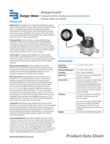
Chapter 1: Product Description
This chapter provides a general description of the Neptune®cellular endpoint for wall and
pit applications.
The cellular endpoint is a compact electronic device that collects meter reading data from
an encoder register at 15-minute intervals, and then transmits the data for collection using
LTE-M cellular technology. The endpoint has an R900®mobile backup message that is
transmitted every 30 seconds in the event the cellular network is unavailable.
The cellular endpoint is easily installed in wall or pit applications. It operates on the LTE-M
cellular networks. The cellular endpoint stops transmissions when the battery discharges
below the normal operating voltage.
Figure 1 – Cellular Endpoint – Wall

Figure 2 – Cellular Endpoint – Pit with External Antenna
Figure 3 – Cellular Endpoint – Pit with Internal Antenna
2 Cellular Endpoint Wall and Pit Installation and Maintenance Guide
Chapter 1: Product Description

Cellular Endpoint Wall and Pit Installation and Maintenance Guide 3
Chapter 2: Specifications
This chapter covers the specifications for the cellular endpoint.
Electrical Specifications
A lithium battery supplies the power.
Transmitter
The following table defines the cellular endpoint transmitter specifications.
Specification Description
Transmit Period Fifteen-minute data delivered four times per day.
R900 mobile backup message transmitted every 60 minutes. If
there are 72 consecutive hours of data delivery failure over the
cellular network, the transmit frequency is increased to every 30
seconds.
Encoder Reading Register interrogated every 15 minutes.
Transmitter Channel 50 (R900 mobile backup).
Transmitter Frequency 902–928 MHz (R900 mobile backup).
Output Power Meets FCC Part 15.247 and FCC Part 27.
FCC Verification Part 15.247.
Table 1 – Transmitter Specifications

Encoder Register Interface
The following table provides information on the maximum cable lengths required for
different registers.
Cable Brand Length
Neptune®ARB®V300 feet (91 meters). Meets manufacturer's published
specifications for wire length between the encoder and the
remote receptacle. The length is based on solid three conductor
wire, 22 AWG.
Neptune®ProRead™,
ProCoder™, MACH 10®,
E-CODER®
500 feet (152 meters).
Sensus Protocol registers 200 feet (61 meters).
Table 2 – Supported Encoder Maximum Cable Length
Environmental
The following table provides the environmental specifications of the cellular endpoint.
Condition Description
Operating Temperature –22° to 149°F (–30° to 65°C).
Storage Temperature –40° to 158°F (–40° to 70°C).
Operating Humidity 0 to 100% condensing.
Table 3 – Environmental Conditions
Functional
The following table provides the functional specifications of the cellular endpoint.
Specification Description
Register Reading Eight digits.
Endpoint ID Nine digits.
Table 4 – Functional Specifications
4 Cellular Endpoint Wall and Pit Installation and Maintenance Guide
Chapter 2: Specifications

Dimensions and Weight
This section provides the dimensions and weight of the cellular endpoint.
Specification Definition
Weight 1.0 lbs (454 grams).
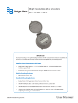
Dimensions, Pit model with Internal Antenna See "Pit Cellular Endpoint " Pit with Internal Antenna – Dimensions
Front and Side in the following image.
Dimensions Wall model with External
Antenna
See Wall Cellular Endpoint with External Antenna – Dimensions Front
and Side on the following page.
Dimensions front and side See Cellular endpoint – Dimensions Front and Side on the following
page.
Figure 4 – Pit Cellular Endpoint with Internal Antenna – Dimensions Front and Side
Cellular Endpoint Wall and Pit Installation and Maintenance Guide 5
Chapter 2: Specifications

Figure 5 – Wall Cellular Endpoint with External Antenna – Dimensions Front and Side
Figure 6 – Cellular Endpoint – Dimensions Front and Side
6 Cellular Endpoint Wall and Pit Installation and Maintenance Guide
Chapter 2: Specifications
/