Page is loading ...

OPERATION AND PARTS MANUAL
Revision #4 (01/06/09)
GloBug
MODEL GB113BC
LIGHTING SYSTEM
(FOR USE WITH MQ SERIES GENERATORS)
To find the latest revision of this
publication, visit our website at:
www.multiquip.com

PAGE 2 — GB113BC GLOBUG LIGHTING SYSTEM — OPERATION AND PARTS MANUAL — REV. #5 (01/16/12)
PROPOSITION 65 WARNING

GB113BC GLOBUG LIGHTING SYSTEM — OPERATION AND PARTS MANUAL — REV. #5 (01/16/12) — PAGE 3
NOTES

PAGE 4 — GB113BC GLOBUG LIGHTING SYSTEM — OPERATION AND PARTS MANUAL — REV. #5 (01/16/12)
MQ GLOBUG LIGHTING
SYSTEM
Proposition 65 Warning ............................................. 2
Table Of Contents ..................................................... 4
Parts Ordering Procedures ....................................... 5
Safety Information .................................................. 6-9
Specifications .......................................................... 10
Dimensions ............................................................. 11
Floodlight Footcandle Plots (BAL-120 Oval) .......... 12
Floodlight Footcandle Plots (BAL-120R Ref.) ......... 13
Floodlight Footcandle Plots (BAL-115D Drum) ...... 14
General Information ................................................ 15
Components....................................................... 16-17
Setup .................................................................. 18-19
Setup/Operation ...................................................... 20
Shutdown ................................................................ 22
Maintenance ...................................................... 22-31
Troubleshooting (Lamps) ........................................ 32
Troubleshooting (Mast) ........................................... 33
Explanation Of Codes In Remarks Column ............ 34
Suggested Spare Parts ........................................... 35
COMPONENT DRAWINGS
Nameplate and Decals Assembly ..................... 36-37
T-Handle Assembly ............................................ 38-39
Steering Assembly ............................................. 40-41
Outrigger Assembly ........................................... 42-43
Mast Adapter Assembly ..................................... 44-45
Main Mast Assembly .......................................... 46-47
Winch Assembly ................................................. 48-49
Mast Section Assembly ...................................... 50-51
Baseplate Cover Assembly ................................ 52-53
Ballast Box Assembly ......................................... 54-55
Fan Blower/Lamp Base Assembly ..................... 56-57
Balloon/Lamp Guard Assembly ......................... 58-59
Terms and Conditions Of Sale — Parts .................. 60
Specification and part number are subject to
change without notice.
NOTICE
TABLE OF CONTENTS

GB113BC GLOBUG LIGHTING SYSTEM — OPERATION AND PARTS MANUAL — REV. #5 (01/16/12) — PAGE 5
www.multiquip.com
Ordering parts has never been easier!
Choose from three easy options:
WE ACCEPT ALL MAJOR CREDIT CARDS!
When ordering parts, please supply:
❒ Dealer Account Number
❒ Dealer Name and Address
❒ Shipping Address (if different than billing address)
❒ Return Fax Number
❒ Applicable Model Number
❒ Quantity, Part Number and Description of Each Part
❒ Specify Preferred Method of Shipment:
✓ UPS/Fed Ex ✓ DHL
■ Priority One ✓ Tr uc k
■ Ground
■ Next Day
■ Second/Third Day
If you have an MQ Account, to obtain a Username
and Password, E-mail us at: parts@multiquip.
com.
To obtain an MQ Account, contact you
r
District Sales Manager for more information.
Order via Internet
(Dealers Only)
:
Order parts on-line using Multiquip’s SmartEquip website!
■ View Parts Diagrams
■ Order Parts
■ Print Specification Information
Note: Discounts Are Subject To Change
Goto www.multiquip.com and click on
Order Parts
to log in and save!
Use the internet and qualify for a 5% Discount
on Standard orders for all orders which include
complete part numbers.*
Order via Fax
(Dealers Only)
:
All customers are welcome to order parts via Fax.
Domestic (US) Customers dial:
1-800-6-PARTS-7 (800-672-7877)
Fax your order in and qualify for a 2% Discount
on Standard orders for all orders which include
complete part numbers.*
Order via Phone:
Domestic (US) Dealers Call:
1-800-427-1244
Best Deal!
International Customers should contact
their local Multiquip Representatives for
Parts Ordering information.
Non-Dealer Customers:
Contact your local Multiquip Dealer for
parts or call 800-427-1244 for help in
locating a dealer near you.
Note: Discounts Are Subject To Change
Effective:
January 1
st
, 2006
NOTICE
All orders are treated as Standard Orders and will
ship the same day if received prior to 3PM PST.
PARTS ORDERING PROCEDURES

PAGE 6 — GB113BC GLOBUG LIGHTING SYSTEM — OPERATION AND PARTS MANUAL — REV. #5 (01/16/12)
SAFETY INFORMATION
Do not operate or service the equipment before reading
the entire manual. Safety precautions should be followed
at all times when operating this equipment.
Failure to read and understand the safety
messages and operating instructions could
result in injury to yourself and others.
SAFETY MESSAGES
The four safety messages shown below will inform you
about potential hazards that could injure you or others. The
safety messages specifically address the level of exposure
to the operator and are preceded by one of four words:
DANGER, WARNING, CAUTION or NOTICE.
SAFETY SYMBOLS
Potential hazards associated with the operation of this
equipment will be referenced with hazard symbols which
may appear throughout this manual in conjunction with
safety messages.
DANGER
Indicates a hazardous situation which, if not avoided,
WILL result in DEATH or SERIOUS INJURY.
WARNING
Indicates a hazardous situation which, if not avoided,
COULD result in DEATH or SERIOUS INJURY.
CAUTION
Indicates a hazardous situation which, if not avoided,
COULD result in MINOR or MODERATE INJURY.
NOTICE
Addresses practices not related to personal injury.
GENERAL SAFETY
CAUTION
NEVER operate this equipment without proper protective
clothing, shatterproof glasses, respiratory protection,
hearing protection, steel-toed boots and other protective
devices required by the job or city and state regulations.
NEVER operate this equipment when not
feeling well due to fatigue, illness or when
under medication.
NEVER operate this equipment under the influence of
drugs or alcohol.
NOTICE
This equipment should only be operated by trained and
qualified personnel 18 years of age and older.
Whenever necessary, replace nameplate, operation and
safety decals when they become difficult read.
Manufacturer does not assume responsibility for any
accident due to equipment modifications. Unauthorized
equipment modification will void all warranties.
NEVER use accessories or attachments that are not
recommended by Multiquip for this equipment. Damage
to the equipment and/or injury to user may result.
ALWAYS know the location of the nearest
fire extinguisher.
ALWAYS know the location of the nearest
first aid kit.
ALWAYS know the location of the nearest phone or keep
a phone on the job site. Also, know the phone numbers
of the nearest ambulance, doctor and fire department.
This information will be invaluable in the case of an
emergency.

GB113BC GLOBUG LIGHTING SYSTEM — OPERATION AND PARTS MANUAL — REV. #5 (01/16/12) — PAGE 7
SAFETY INFORMATION
LIGHTING SYSTEM SAFETY
DANGER
NEVER use lighting system in rain, snow or
areas of high humidity that could generate
electrical storms.
WARNING
NEVER disconnect any emergency or safety devices.
These devices are intended for operator safety.
Disconnection of these devices can cause severe injury,
bodily harm or even death. Disconnection of any of
these devices will void all warranties.
CAUTION
NEVER attempt service on a running machine.
NOTICE
To prevent the lighting system from overturning, NEVER
use in winds that exceed 22mph (10 m/s).
The lighting system should only be used in temperatures
between 23° to 104°F (-5° to 40° C). Failure to comply
with these operating parameters could cause the lamp
to malfunction and shorten the ballast life.
ALWAYS keep the lighting system in proper running
condition.
Fix damage to lighting system and replace any broken
parts immediately.
ALWAYS store equipment properly when it is not being
used. Equipment should be stored in a clean, dry location
out of the reach of children and unauthorized personnel.
LAMP SAFETY
WARNING
NEVER attempt to replace lamp with the power on.
Always unplug the power cord from the generator or
power source when changing the lamp.
ALWAYS allow a sufficient amount of time for the lamp to cool
before changing. The possibility exists of severe burns.
CAUTION
NEVER use force when installing the lamp. Excessive force
could cause the lamp to break, causing bodily harm.
NOTICE
NEVER leave any grease or oil residue on lamp surface
when replacing or removing lamp. This can create hot
spots, reducing the service life of the lamp.
ALWAYS make sure lamp surface is clean and dry.
ALWAYS replace with MQ recommended type lamp. See
parts section of this manual.
If applicable, ALWAYS make sure the lamp guard is
installed correctly. NEVER deform the lamp guard.
NEVER unplug the lamp’s AC power cable during
operation.
ALWAYS have a trained technician to install and
remove lamp or replace any damaged fixture wiring.
BALLOON SAFETY
WARNING
To prevent serious burns, NEVER touch
or unzip the balloon envelope when the
lamp is on.
CAUTION
ALWAYS keep the balloon away from sharp objects and
excessive amounts of heat.
NOTICE
To prevent balloon deformation, NEVER use lighting
system in strong winds.
DO NOT place the balloon inside its protective cover
until the lamp has had a sufficient amount of time to cool
down. This will prevent the balloon’s nylon cover from
being burned (touching the lamp surface).
ALWAYS place the balloon inside its protective cover
after each use. This will prolong the life of the balloon
material, keeping it protected from harsh environmental
elements.
Replace balloon immediately if damaged. A damaged
balloon will not inflate properly, and may become more
damaged by touching the hot lamp surface.
DO NOT use excessive force when zipping and unzipping
the balloon. Be gentle with the zipper mechanism. If the
zipper is broken, the balloon will become unusable.

PAGE 8 — GB113BC GLOBUG LIGHTING SYSTEM — OPERATION AND PARTS MANUAL — REV. #5 (01/16/12)
SAFETY INFORMATION
GENERATOR SAFETY
If using a generator to power lighting system,
refer to applicable generator manual safety
information section.
ELECTRICAL SAFETY
DANGER
Lighting system is equipped with a ground pin on the
power plug. For your protection, ALWAYS complete the
grounding path. NEVER insert the AC power plug into a
2-prong receptacle to operate lighting system.
When applying power to the lighting system, ALWAYS
connect the AC power plug to a 3-prong receptacle that
is grounded. The possibility exists of electrical shock,
electrocution and even death if the lighting system is
not grounded.
NEVER operate lighting system or
handle any electrical equipment while
standing in water, while barefoot,
while hands are wet or in the rain. A
dangerous electrical shock could
occur, causing severe bodily harm
or even death.
ALWAYS make sure the area above
the lighting system is open and clear
of overhead power lines and other
obstructions. Contact with overhead
power lines or other obstructions
could result in equipment damage,
electrical shock, electrocution and
even death.
Power Cord/Cable Safety
DANGER
NEVER let power cords or cables lay in water.
NEVER use damaged or worn cables or cords. Inspect
for cuts in the insulation
NEVER grab or touch a live power
cord or cable with wet hands. The
possibility exists of electrical shock,
electrocution or death.
Make sure power cables are securely connected.
Incorrect connections may cause electrical shock and
damage to the lighting system.
NOTICE
ALWAYS make certain that proper power or extension
cord has been selected for the job. See Cable Selection
Chart in this manual.

GB113BC GLOBUG LIGHTING SYSTEM — OPERATION AND PARTS MANUAL — REV. #5 (01/16/12) — PAGE 9
SAFETY INFORMATION
LOADING AND UNLOADING
If lighting system is equipped with a transport lifting hook,
refer to the following safety information.
CAUTION
Before lifting, make sure that lighting system parts are
not damaged and screws are not loosened or lost.
ALWAYS make sure crane or lifting device has been
properly secured to lifting hook of the equipment.
NEVER lift the equipment while lighting system is
running.
Make sure the mast is completely lowered before lifting
the lighting system.
Use adequate lifting cable (wire or rope) of sufficient
strength.
Use one point suspension hook and lift straight upwards.
Never allow any person or animal to stand underneath the
equipment while lifting.
DO NOT lift machine to unnecessary heights.
TRANSPORTING SAFETY
NOTICE
When transporting the lighting system, if applicable,
always place in stow position and place mast in its
carrying case.
ALWAYS remove balloon/lamp assembly from the mast
when transporting lighting system. This will prevent
damage to the bulb due to vibration.
NEVER leave the balloon/lamp exposed during transport.
Exposure to excess wind or rain could damage the
balloon’s nylon cover.
ALWAYS place balloon inside its protective cover during
transport. Be sure the cover is secured tightly around the
balloon/lamp assembly.

PAGE 10 — GB113BC GLOBUG LIGHTING SYSTEM — OPERATION AND PARTS MANUAL — REV. #5 (01/16/12)
snoitacificepS.1elbaT
guBolG
ledoMCB311BG
egatloVtupnICAV021
ycneuqerFesahP-elgniSzH06
tnerruC.xaMspmA6.9
rotareneGhtiwytilibatSdniW)
hpk64.08(hpm56
)rotarenegssel(thgieW)gk521(.sbl672
pmaL
epyTpmaLedadilaHlateMttaW0001)1(
snemuL000,211
)°063(
egarevoCthgiL)sretem27.54(.tf051
)lanidutignoL(erutarepmeTecafruS.xaM)C°742(F°6.674
)lasrevsnarT(erutarep
meTecafruS.xaM)C°412(F°2.714
rotoMnaF
rotoMnaFnoollaBzH06,CAV511
tnerruC.xaMspmA063.
erusserP)APk6.512(ISP62.
13
noollaB
retemaiD)sretem2.1(.TF9.3
lairetaMnolyNtnatsiseRtaeH
erutarepmeTgnitsiseRtaeH)C°081~061(F°653~023
erutarepmeTgnitleM)C°062(F°005
noollaBfoerutarepmeTlanretnIegarevA)C°25(F°621
ecnatsiseRretaWHmm005,1
2
0
tsaM
segatSforebmuN))3(CB311BG
thgieHmumixaM)sretem44.4(.TF85.41
snoisnemiD
2elbaT,1erugiFeeS
rotareneG
laun
aMrotareneGdeificepSeeS
SPECIFICATIONS

GB113BC GLOBUG LIGHTING SYSTEM — OPERATION AND PARTS MANUAL — REV. #5 (01/16/12) — PAGE 11
Figure 1. Dimensions
TOP VIEW
SIDE VIEW
REAR VIEW
STOW POSITION
A
B
F
E
G
H
D
C
I
J
SNOISNEMID.2ELBAT
ecnerefeR
retteL
noitpircseD).mm(.tfnoisnemiD
ecnerefeR
retteL
noitpircseD).mm(.tfnoisnemiD
AesaBleehW).mm008(.
tf26.2F )noitisoPdeyolpeDtsaM(thgieH.xaM).mm544,4(.tf85.41
B)noitisoPdewotStsaM(thgieH).mm047,1(.tf7.5G )leehWr
aeRottnorF(htgneL).mm040,1(.tf14.3
CthgieHeldnaH).mm878(.tf88.2H )reggirtuOotleehWtnorF(htgneL).mm055,1(.tf80
.5
DhtgneLgaBnoollaB).mm686(.tf52.2I retemaiDnoollaB).mm341,1(.tf57.3
EmroftalPotkooHtfiL).mm955(.tf38.1J )deyolpe
DsreggirtuO(htdiW).mm006,1(.tf42.5
DIMENSIONS

PAGE 12 — GB113BC GLOBUG LIGHTING SYSTEM — OPERATION AND PARTS MANUAL — REV. #5 (01/16/12)
Figure 2. Floodlight Footcandle Plot (Bal120- Oval Shaped)
Based on 360°glare-free coverage.
10
5
2
1
.5
.25
VALUES LISTED AS FOOTCANDLES
SCALE: 1 GRID = 50 FT. (15.24 METERS)
FLOODLIGHT FOOTCANDLE PLOT

GB113BC GLOBUG LIGHTING SYSTEM — OPERATION AND PARTS MANUAL — REV. #5 (01/16/12) — PAGE 13
Figure 3. Floodlight Footcandle Plot (BAL120R-Reflector-Shaped Balloon)
Based on 360°glare-free coverage.
10
5
2
1
.5
.25
VALUES LISTED AS FOOTCANDLES
SCALE: 1 GRID = 50 FT. (15.24 METERS)
FLOODLIGHT FOOTCANDLE PLOT

PAGE 14 — GB113BC GLOBUG LIGHTING SYSTEM — OPERATION AND PARTS MANUAL — REV. #5 (01/16/12)
Figure 4. Floodlight Footcandle Plot (BAL-115D-Drum Shaped Balloon)
Based on 360°glare-free coverage.
10
5
2
1
.5
.25
VALUES LISTED AS FOOTCANDLES
SCALE: 1 GRID = 50 FT. (15.24 METERS)
FLOODLIGHT FOOTCANDLE PLOT

GB113BC GLOBUG LIGHTING SYSTEM — OPERATION AND PARTS MANUAL — REV. #5 (01/16/12) — PAGE 15
The Multiquip GloBug Lighting System is a general purpose
floodlight tower intended for emergency and remote lighting
conditions. The GloBug can be powered by a variety of
Multiquip's series generators. Power requirements for running
the GloBug are 120 VAC, 60 Hz @ 9.6 amps. The GloBug
can be powered by any MQ portable generator with an output
of 2.9 kW or greater.
The lighting system of Multiquip's GloBug Lighting System
is comprised of one "Metal Halide" 1000 watt lamp. This
lamp has an output of 112,000 lumens. Typical lighting
coverage is in excess 150 ft. (45.72 meters) in a 360 degree
pattern.
Located underneath the generator support platform is a
weather resistant ballast box that contains the ballast for
starting the floodlight. The floodlight is activated by an
ON/OFF switch located at the base of the mast.
For ease of service or transport, the floodlight is equipped
with a quick-disconnect connector that allows the lamp fixture
to be removed quickly. This feature is extremely useful during
transport of the lighting system over rough terrain. It is always
best to remove the floodlight and pack it safely so it will not
be damaged.
ALWAYS make sure the
area above GloBug is
open and clear of
overhead power lines
and other obstructions.
The tower extends in
excess of 14.58 ft. (4.44
meters). Contact with
overhead powerlines or
other obstructions could
result in equipment
damage,
Serious Injury or Death
!
DANGER - GloBug Overhead Obstructions
A
C
C
I
R
C
U
I
T
B
R
E
A
K
E
R
A
C
C
IR
CUIT
BREAKER
120
/
2
40V
120
/240
V
3
0
A
30A
1
20V
3
0
A
2
0A
2
0
A
0
N
O
F
F
I
D
L
E
C
O
N
T
R
O
L
O
P
E
R
A
T
I
O
N
S
W
I
T
C
H
O
N
O
F
F
F
U
L
L
P
O
W
E
R
S
W
I
T
C
H
12
0
V
1
2
0
V
/
24
0
V
1
2
0
V
O
F
F
OFF
2
1A
21
A
G
A
-
6
H
6
0
0
0
The lighting system can be raised vertically in excess of 14.58
feet (4.44 meters) by means of a manual winch. The tower
tensioning system is designed to provide the necessary tension
to safely control the pivot of the tower. Outriggers must always be
deployed prior to raising the mast.
NOTE
All information related to the
generator will be referenced in a
separate (supplied) "Operation
and Parts Manual". Operation
and maintenance of the generator
will not
be referenced in this
manual.
Alarm Buzzer
The GloBug is equipped with a "Balloon Alarm" feature. This
alarm will sound if the lamp is on and the balloon attempts to
make contact with the
hot!
surface of the lamp . This alarm
is intended to inform the operator that a potential burn hazard
exits between the lamp surface and the balloon material.
Always allow the lamp to cool down before removing the AC
power from the GloBug. In the event the balloon begins to
deflate during normal operation, immediately place the
GloBug's ON/OFF switch in the OFF position.
Please read carefully the specified
generator manual that will accompany your
GloBug lighting system. This manual will
explain how to operate and maintain the
generator.
Balloon Envelopes
The GloBug can be configured with a variety of balloon
envelopes (canopy). Please contact the MQ sales department
for the balloon of your choice. The GloBug, Model GB113BC
is shipped from the factory with the drum type balloon.
Machine Safety Decals
The GloBug is equipped with a number of safety decals.
These decals are provided for operator safety and
maintenance information. The decal illustrations shown in
the parts section of this manual show the decals as they
appear on the machine. Should any of these decals become
unreadable, replacements can be obtained from your dealer.
GENERAL INFORMATION

PAGE 16 — GB113BC GLOBUG LIGHTING SYSTEM — OPERATION AND PARTS MANUAL — REV. #5 (01/16/12)
Figure 5. Major Components
COMPONENTS

GB113BC GLOBUG LIGHTING SYSTEM — OPERATION AND PARTS MANUAL — REV. #5 (01/16/12) — PAGE 17
Figure 5 shows the location of the controls and components
for the GloBug Lighting System. The functions of each control
is described below:
1. Steering Handle – The GloBug can be moved in either
a forward or reverse direction by pulling back or pushing
forward on the T-handle. In addition the front wheels are
designed to turn in the opposite direction of the T-handle
placement thus allowing the GloBug to turn either left or
right.
2. Mast Winch – Use this mechanical winch to raise and
lower the mast. Always be on the lookout for overhead
obstructions. Keep immediate area free of bystanders
and debris when raising the mast.
3. Lamp Power Cable (Generator) – Connect this quick-
disconnect cable plug (generator-side) to the lamp power
cable plug.
4. Mast – This mast is comprised of three separate stages.
The mast can be raised in excess of 14.58 ft. (4.44
meters). Again when raising the mast, always be on the
lookout for overhead obstructions.
5. Lift Hanger – When lifting of the GloBug is required
always use a suitable lifting device of adequate lifting
capability. NEVER stand underneath the GloBug while it
is being lifted.
6. Generator – MQ GA-Series type generator. This genera-
tor will supply the necessary power to run the GloBug. For
operation of generator read generator Operation Manual
supplied with GloBug.
7. Tires – The GloBug uses 4 pneumatic type tires. Replace
with only recommended type tire . NEVER allow the rear
tires to go flat. This could adversely affect the braking
system. Inflate tires to 35.5 psi (245kPa).
8. Locking Clamps – To secure the generator to the
GloBug cart platform, place clamps (4) around the pipe
frame of the generator. Tighten securely to prevent
movement.
9. Brake Pad – When the brake pedal is pressed, this pad
will strike and hold the rear tires in place. Make sure rear
tires are inflated to the correct air pressure.
10. Outriggers – ALWAYS deploy the outriggers when
raising the mast.
11. Brake Pedal – Step on this pedal to apply the brakes. To
release the brakes, press down on brake pedal again.
12. ON/OFF Switch – Place this switch in the ON position
to turn on the lamp. To turn off the lamp place in the down
position (OFF). Please wait for approximately 10 minutes
before attempting to turn the lamp back on.
13. Power Cable – Connect this cable to a 120 VAC, 60 Hz
power source.
14. Balloon Storage Bag – Store the balloon in this storage
bag when the GloBug is not in use. Allow a sufficient
amount of time for the lamp to cool down before placing
balloon inside storage bag. Possibility exists of balloon
getting burned.
15. Balloon – This balloon is made of heat resistant nylon,
with a diameter of 3.9 ft. (1,150 mm). The balloon shall be
inflated to a pressure of 31.26 psi (215.6 kPA).
16. Lamp Power Cable (Balloon) – Connect this quick-
disconnect cable plug (balloon-side) to the generator
power cable plug.
17. Fan Motor (Blower) – This electric motor is responsible
for inflating the balloon. It will supply a pressure of 31.26
psi (215.6 kPA). Please note that the balloon will begin to
inflate as soon as power is applied to the GloBug. The
OFF/ON switch
does not
control the electric fan motor.
18. Lamp Guard – This guard (cage) protects the lamp from
being hit by objects.
19. Lamp – 1000 watt metal-halide type lamp. Replace with
only MQ recommended type lamp. Always allow a
sufficient amount of time for the lamp to
cool down
before changing.
20. Lamp Holder – Screw lamp into this holder. If lamp
becomes difficult to screw into holder or holder is
damaged, replace holder.
21. Balloon Alarm Buzzer – Will sound during normal
operation if the balloon attempts to make contact with the
lamp's
hot!
surface. If this condition occurs, immediately
place the GloBug's ON/OFF switch in the OFF position.
22. Adjust Lever – This lever allows the lamp to be posi-
tioned up or down. Turn counterclockwise to release lamp
and position. Turn clockwise to tighten.
23. Ballast Compartment – Provides the necessary elec-
tronics to light the lamp. To gain access to the ballast
compartment the generator must be removed from the
cart platform.
COMPONENTS

PAGE 18 — GB113BC GLOBUG LIGHTING SYSTEM — OPERATION AND PARTS MANUAL — REV. #5 (01/16/12)
CAUTION - Read Manual
Please read this entire manual carefully
before attempting to operate the GloBug.
Failure to read this manual could cause
damage to the GloBug and serious injury
to the operator.
GloBug Setup
1. Using the T-handle (Figure 6) place the GloBug on a
firm level surface
so that it will not slide or turn over.
3. Lift up on each outrigger (2) from its stow position, rotate
backwards and place it in the deployed position, as shown
in Figure 8. The outriggers will automatically lock in place
once they touch the ground,
Figure 6. T-Handle (Directional Control)
2. To apply the parking brake (Figure 7), step on the brake
pedal and pull back on the T-handle. This will lock the
rear wheels. For additional safety use chock blocks to
prevent rolling.
PARKING
BRAKE SET
STEP DOWN
ON BRAKE PEDAL
Figure 7. Parking Brake (Set Position)
A
C
C
I
R
C
U
I
T
B
R
E
A
K
E
R
AC
CIR
CUIT
B
RE
AK
E
R
1
2
0
/
2
4
0
V
120
/240V
3
0
A
30A
1
2
0
V
3
0
A
2
0
A
2
0
A
0
N
O
F
F
I
D
L
E
C
O
N
T
R
O
L
O
P
E
R
A
T
I
O
N
S
W
I
T
C
H
O
N
O
F
F
F
U
L
L
P
O
W
E
R
S
W
I
T
C
H
1
2
0
V
1
2
0
V
/
2
4
0
V
1
2
0
V
O
F
F
OFF
2
1
A
21A
G
A
-
6
H
6000
OUTRIGGERS
DEPLOYED
STOW
POSITION
Figure 8. Outriggers (Deployed Position)
4. Expose the balloon by pulling down on the velcro tabs
and unzip the protective cover as shown in Figure 10.
Next, fold the protective cover into itself and zip.
Figure 9. Exposing the Balloon.
SETUP

GB113BC GLOBUG LIGHTING SYSTEM — OPERATION AND PARTS MANUAL — REV. #5 (01/16/12) — PAGE 19
5. To position the balloon, simply loosen
the adjustment lever by turning it counter-
clockwise and either push down or up
on the lever. Pushing
down
on the lever
will cause the balloon to rise. Pushing
up
on the lever will allow the balloon to
be lowered. See insert A in Figure 10.
For circular positioning, swing the lever
to the desired position. See insert B in
Figure 11.
Figure 10. Positioning the Balloon
6. Before raising the mast, make sure the mast set screw
(Figure 11) is securely tightened (use an 5mm-allen
wrench to tighten). This will prevent the balloon/lamp
assembly from falling off. In addition make sure the power
cable from the generator is connected to the lamp power
cable.
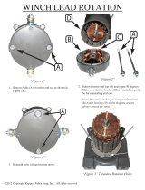
Figure 11. Mast Set Screw/Power Connections
7. Using the mechanical winch (Figure 12),
raise
the mast
to the desired height. Turn winch handle clockwise to
raise mast.
Figure 12. Mechanical Winch Handle
CAUTION - MAST PINCH POINT
When raising or lowering the mast, keep hands and fingers
clear of the various mast sections, this will prevent hands
and fingers from getting pinched.
SETUP

PAGE 20 — GB113BC GLOBUG LIGHTING SYSTEM — OPERATION AND PARTS MANUAL — REV. #5 (01/16/12)
DANGER - HIGH VOLTAGE POWER LINES
When raising mast, ALWAYS be on
the lookout for overhead obstructions
such as high voltage power lines. The
possibility exists of electrocution,
even death! if the GloBug comes in
contact with
high voltage power lines
.
Applying Power
1. Make sure the power ON/OFF switch (Figure 13) located
near the bottom of the mast is in the OFF position.
2. The GloBug has a power requirement of 120 VAC, 60 Hz
@ 9.6 amps. Connect the GloBug's AC power cord to
the 120 VAC twist-lock receptacle (Figure 14) on the the
supplied generator.
Figure 13. Power OFF/ON Switch (OFF Position)
Figure 14. 120 VAC Receptacle
CAUTION - READ GENERATOR MANUAL
Before attempting to operate the
generator, READ the entire operation
section of the manual. Failure to read
manual could cause severe damage to
the equipment and bodily harm to the
operator.
4. Notice that the balloon envelope will begin to deploy as
soon as power is applied by an active generator. This
function
is not
controlled by the power ON/OFF switch.
5. Wait until the balloon is fully deployed before attempting
to turn on the lamp. The possibility exists of the balloon
getting burned (touching the lamp).
6. If the balloon is fully deployed, place the GloBug's ON/
OFF switch (15) in the ON position.
Figure 15. Power OFF/ON Switch (ON Position)
7. The lamp should now be on. If the lamp is not on, check
all connections and repeat steps 1 through 6. If the lamp
still does not come on contact the MQ service
department.
Shutdown
1. Place the power ON/OFF switch (Figure 16) in the OFF
position.
Figure 16. Power OFF/ON Switch (OFF Position)
CAUTION - LAMP COOL DOWN
Allow a sufficient amount of time (15-20 minutes) for the
lamp (Figure 17) to
cool down
before turning off
generator. The possibility exists of the balloon getting
burned (touching the lamp).
2. Disconnect the GloBug's AC power cable from the
generator. The balloon should begin to deflate.
3. Shutdown generator as referenced in the "Shutdown
Section" of the supplied generator manual.
3. Start the generator as referenced in the "Start-up
Section" of the supplied generator manual.
ON
OFF
ON
OFF
ON
OFF
SETUP/OPERATION
/