Page is loading ...

P-047550-1874 ISSUE 1 © 1999
CHESHIRE, CT 203-699-3300 FAX 860-677-7746
Installation Instructions for the
7005-G5 Hotel Room Annunciator
Description
The 7005-G5 Hotel Room Annunciator Kit alerts hearing-impaired
individuals inside a room that someone is present outside the
room. The horn/strobe is mounted inside the room. When the
pushbutton outside of the room is pressed for 5 seconds, the signal
is activated. The 7005-G5 Hotel Room Annunciator Kit contains:
Pushbutton (Cat. No. 620), Pushbutton Mounting Plate (Cat. No.
147-10), Horn/Strobe (Cat. No. 6536-G5), and Transformer (Cat.
No. 592). You can purchase each item separately from your local
Edwards distributor.
Installation
A qualified electrician familiar with National Electrical Code
and local code requirements must install this product. Failure to
follow the safety precautions in this instruction sheet could result
in product or property damage, severe personal injury or death.
WARNING
To reduce the risk of shock, do not connect AC power
until installation is complete.
WARNING
To reduce the risk of shock, do not remove lens or
tamper with unit when the circuit is energized.
Disconnect power and allow five (5) minutes for
stored energy to dissipate before starting work or
disassembly. High energy could be stored in the
strobe circuit once it is energized.
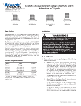
1. Install Cat. No. 620 Pushbutton and Cat. No. 147-10 mounting
plate (Figures 1 and 2)
a. Insert the back of the pushbutton through the hole in the
mounting plate. Press on the button until it is properly
seated within the hole.
b. Install a single gang 2" x 4" (51 mm x 102 mm) electrical
box using suitable hardware.
c. Extend black and white wires using 18 AWG wire and
connectors (not supplied). Route extended wires to the
horn/strobe and transformer (polarity is not important).
Ground in accordance with local codes and regulations.
d. Mount the pushbutton switch onto the electrical box
using 2 screws supplied with the Cat. No. 147-10
mounting plate.
e. If additional pushbuttons are required, follow steps a and
b above. Then, extend black and white wires using 18
AWG wire and connectors (not supplied). Route extended
wires to the previously installed pushbutton switch and
connect wire leads (Figure 1).
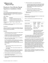
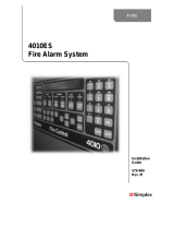
2. Install Catalog No. 6536-G5 horn/strobe (Figures 1 and 4).
The 6536-G5 horn/strobe can be mounted on any single gang
2" x 4" (51 mm x 102 mm) electrical box, double gang 4" x 4"
(102 mm x 102 mm) electrical box, or standard 4" x 4" (102
mm x 102 mm) junction box with a plaster ring.
a. Install an appropriate electrical box using suitable
hardware.
b. Connect one wire from the 620 pushbutton to one of the
horn/strobe wires (polarity is not important).
c. Extend the remaining horn/strobe wire to the transformer.
d. Mount the horn/strobe onto the electrical box using two
screws (supplied).
3. Install Catalog No. 592 Transformer (Figures 1 and 3).
a. Select a metal electrical box that can be grounded. Mount
the transformer onto the electrical box (Figure 3) so that
it has ground continuity to the box and conduit system.
b. Install the box using suitable hardware.
c. Ground the box in accordance with local codes and
regulations.
d. Connect the remaining pushbutton wire to one of the
terminals marked 24V 20VA.
e. Connect the horn/strobe wire to the second terminal
marked 24V 20VA.
f. Connect the transformer's primary wire leads to an
appropriate 120V AC power source.
4. When all connections are completed, press the pushbutton
and verify operability of the horn/strobe.
Maintenance
Perform regularly scheduled testing at least twice a year or more
often as dictated by local authorities having jurisdiction.
The 7005-G5 Hotel Room Annunciator is not serviceable or re-
pairable. Should it fail to operate properly, contact the supplier
for replacement.
Table 1. Specifications
Horn/strobe Voltage 24V 50/60 Hz 24V DC
Horn/Strobe Current 175 mA 125 mA
Transformer - Primary 120V
- Secondary 24V 20VA

Figure 1. Connecing Catalog No. 7005-G5 Hotel Room Annunciator
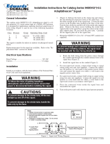
Figure 3. Catalog No. 592 Transformer
Figure 2. Catalog No. 620 and Catalog No. 147-10
Figure 4. Catalog No. 6536-G5 Horn/Strobe
Mounting on Box: Remove
appropriate 1/2" (13 mm) knockout
from electrical box. Loosen the
screw from transformer bracket
and position the transformer on the
back box so that the bracket
extends into the box. Tighten the
screw.
Surface Mounting:
Use foot-mounts
Enclosed Mounting: Mount inside a standard
two gang electrical box using a Catalog 593
plate.
P-047550-1874 ISSUE 1
4 1/2"
(114 mm)
2 3/4"
(70 mm)
ROOM FOR
HANDICAPPED
Mounting
screws
Pushbutton
To 591
To 6536-G5
PLEASE DEPRESS
BUTTON
5 SECONDS
SIGNAL
STROBE
4 1/2"
(114 mm)
4 9/16"
(116 mm)
Strobe
+
_
To 591
Horn
Mounting
screws
FRONT
VIEW
BACK
VIEW
Factory installed
wires
To 620
8V 10VA
16V 10VA
24V 20VA
2 1/4"
(57 mm)
2 1/8"
(54 mm)
2"
(50 mm)
31/32"
(24.6 mm)
2 5/16"
(56.7 mm)
S
H
592 Transformer
120V 60 Hz
24V 20VA
Horn/
Strobe
Additional
Cat. No. 620
and
Cat. No. 147-10
(purchased
separately)
Grounded
metal electrical
box for 592
To 120V AC
power source
Electrical
box for
6536-G5
Electrical box for
Cat. No. 620 and
Cat. No. 147-10
Electrical box for
Cat. No. 620 and
Cat. No. 147-10
/