Page is loading ...

DX100B, DX100BT, DX100BP, ';%%3DX100BHT & DX100BHPT
Toilet/Bathroom Fans
Installation and operating instructions.
Please leave this leaflet with the fan for the benefit of the user.
Installing the fan
These appliances are intended for connection to fixed wiring.
Check that the electrical rating shown on each fan matches the mains supply.
THESE APPLIANCES ARE DOUBLE INSULATED AND DO NOT REQUIRE AN
EARTH CONNECTION.
All installations must be supervised by a qualified electrician. Installations and wiring
must conform to current IEE Regulations (UK), local or appropriate regulations (other
countries).
This appliance is not intended for use by persons (including children and the
infirm persons) with reduced physical, sensory or mental capabilities, or lack of
experience and knowledge, unless they have been given supervision or
instruction concerning use of the appliance by a person responsible for their
safety.
Children should be supervised to ensure they do not play with the appliance.
If you have any queries before installing these products or after they have been
installed, call the Xpelair Technical Hotline +44 (0) 844 372 7766. Our engineers are
there to help you during normal office hours (UK only) and may be faxed at all other
times on +44 (0) 844 372 7767.
Customers outside the UK should contact your local Xpelair distributor.
Description
All DX100B Range fans are single speed extraction and have the following features:
DX100B
';%%3 - Operate the fan using an on/off switch (not supplied).
DX100BP - Operate the fan using an integral pull-cord.
DX100BT - Built-in timer operates fan for a preset delay of up to 30 minutes.
DX100BHT - Operates when triggered automatically by the humidity sensor. Built-in
timer automatically operates the fan for a pre-set delay of 2 to 30
minutes once humidity drops below the pre-set Relative Humidity (RH)
value. Light indicates when the fan is operating in manual mode
DX100BHPT - when turned on using the integral pull cord switch, light indicates when
the fan is operating in manual mode.
In automatic mode the built-in timer automatically operates the fan for
a pre-set delay of 2 to 30 minutes once humidity drops below the
preset Relative Humidity (RH) value.
In manual mode when the fan is switched off, it goes into automatic
mode after the time delay. Light indicates when the fan is operating in
manual mode
What the installer will need
• A means for disconnection in all poles must be incorporated in the fixed wiring in
accordance with wiring regulations (wall or ceiling mounted).
6XLWDEOHIL[LQJV
• If metal switch boxes are used, earthing regulations must be followed.
• Suitably rated 2-core cable – DX100B / DX100BP / DX100BHPT
• Suitably rated 3-core cable – DX100T/ DX100BHT
• 3mm electrician’s screwdriver and No.1 or 2 Pozi drive screwdrivers.
• A wall or ceiling on/off switch – DX100T/ DX100BHT.
It is recommended to use a switch with an indicator light.
• Junior hacksaw (if installing in a window or panel less than 16m thick).
If wall mounting the fan, you will also need
• An appropriate Wall Kit including telescopic wall tube and back draught shutter.
• Alternatively, an appropriate Wall Grille and ƒ100mm ducting.
• A masonry drill, hammer & chisel (or core drill equipment if available).
• Mortar to make good the hole around the ducting.
If window/panel mounting the fan, you will also need
• An appropriate Glass fixing Kit.
• You will need a window pane between 3mm and 6mm thick (preferably 4mm).
• Do not install in glass 3mm thick if the windowpane area is more than 0.2sq.m.
• If installing in sealed double glazing, a specially manufactured unit should be
obtained from the glazing manufacturer, you will also require a special kit, Xpelair Cat.
ref.DXBDG.
• If installing in sash windows, you should mount the fan in the upper window. Secure
the upper sash in the closed position and fit stops just below the level of the fan, to
prevent damaging it when the sash is raised.
• If installing in a panel which is between 9mm and 46mm thick, you will need a special
kit, Xpelair Cat. ref. DXBDG. Do not install these fans in a panel which is more than
46mm thick.
• To prevent a possible hazardous situation from water ingress, an appropriate
condensation trap must be fitted as close as possible to the fan in all situations
where any section of the duct work is positioned higher than the fan itself.
Where to locate the fan
• Locate it as high as possible.
• At least 110mm from the edges of the mounting surface to the centre of the hole.
• As far away as possible from and opposite to the main source of air replacement to
ensure airflow across the room (e.g. opposite the internal doorway).
• Near the source of steam or odours.
• Not where ambient temperatures are likely to exceed 50°C.
• If installed in a kitchen fans must not be mounted immediately above a cooker
hob, or eye level grill.
• If installing in a room containing a fuel burning device which has a non-
balanced flue, it is the installer's responsibility to ensure that there is enough
replacement air to prevent fumes being drawn down the flue when the fan is
operating up to maximum extract.
Refer to Building Regulations for specific requirements.
• Exhaust air must not be discharged into a flue used for exhausting of fumes
from appliances supplied with energy other than electric. Requirements of all
authorities concerned must be observed for exhaust air discharge and intake
flow rates.
• When intended for use in possible chemical corrosive atmospheres, consult
out Technical Service Department. (For overseas markets contact your local
Xpelair distributor).
Installing the isolating switch and cables
1. Check that the electrical rating shown inside the backplate matches your
mains supply.
2. It is intended that this product is directly wired to a fixed outlet.
3. If no supply is readily available it will be necessary to install this wiring. This should
be done by a qualified electrician.
4. It is acceptable to use the lighting circuit ring main for this product.
5. A suitable isolating switch will required, which must be situated so that it cannot be
touched by persons making use of the bath, shower, or hand basin.
6. It is recommended an on/off switch is installed as well as the isolating switch.
7. Only when this wiring is in place should you proceed with the installation.
Preparing the hole
If working above ground floor level, safety precautions must be observed.
WARNING: EYE PROTECTION MUST BE WORN DURING ALL DRILLING AND
CHISELLING OPERATIONS.
If installing in a Wall
1. Check there are no buried pipes or cables in the wall or obstructions on the
outside e.g. electricity, gas, water. If in doubt, seek professional advice.
2. Mark on the wall the centre of the duct hole. The centre of the hole should be at
least 110mm away from the edge of the mounting surface.
3. Use this centre to mark a circle to suit the wall duct (ƒ115mm).
If core drill equipment is available:
4a. Use as directed by core drill manufacturer.
If core drill equipment is not available
4b. Drill a centre hole right through the wall.
5. Cut the hole. (The recommended method is to drill a series of holes, close together,
around the edge of the cutting line and remove the brick between the holes with a
chisel).
6. Go outside and cut a hole in the outer wall, repeating the process above.
7. Cut ducting to the correct length if required.
8. Fit the ducting. Ensure that the duct slopes down away from the fan to allow
drainage of any incoming rain water to the outside.
9. Make good the hole. Allow the mortar to set before continuing the fan installation
If installing in a window or panel
1. Cut a hole, 125mm in diameter or if installing in a window, obtain a ready cut pane.
2. The centre of the hole should be at least 110mm away from the edge of the panel
or pane of glass.
If installing in a ventilation shaft
1. Check there are no buried pipes or cables in the ventilation shaft.
If in doubt, seek professional advice.
2. Cut a hole ƒ110mm, in the side of the shaft.
3. If the shaft has cavity wall, use the wall tube to bridge the cavity.
4. Fit ducting and condensation trap if necessary, positioning condensation trap as
near to the fan as possible.
If installing in a ceiling
1. Check there are no buried pipes or cables in the ceiling/joists etc.
If in doubt, seek professional advice.
2. Cut a hole ƒ115mm.
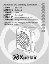
Preparing the fan for installation
Remove the front cover by pressing the release catches located on the sides of the
unit with a 3mm screwdriver, whilst pulling the front cover forward (fig. G).
Mount the fan in the hole
If working above ground floor level, safety precautions must be observed.
If installing in a wall, ceiling or vent
Mark the position of the backplate (fig A).
1. Hold the backplate so that the terminal block faces you in the top left hand corner
and the lip points towards the hole.
2. Carefully insert the lip into the wall duct/ceiling or vent shaft.
3. Adjust the position of the backplate until it is level.
4. Mark on the wall/ceiling or vent shaft the positions of the four fixing holes in the
backplate.
5. Remove the back plate from the ducting.
6. Drill screw holes in these positions if necessary, and fit wall plugs if necessary.
Mount the backplate (fig B).
1a. If installing in a vent, an appropriate Vent Kit is required.
1b. If installing in a ceiling, appropriate termination ancillaries are required.
Follow instructions provided.
2. If wiring the fan from behind, remove knockout. Feed the mains cable through the
cable entry hole in the back plate to the terminals (fig. C).
3. If wiring from above, leave the cable free to be fitted into labyrinth.
4. Insert the lip of the backplate into the wall duct/ceiling or vent shaft as before.
5. Fasten the backplate to the wall/ceiling or vent shaft using appropriate fasteners.
If using screws, do not over tighten.
6. If installing in a wall, an appropriate Wall Grille is required.
Follow instructions provided.
If installing in a window or panel
1. If installing in a window or panel no more than 9mm thick, an appropriate Glass
Kit is required. Follow instructions supplied.
Cutting back the Spigot (if required)
If installing in a window or panel less than 16mm thick, the fan spigot needs to be
cut back to the visible step 20mm away from the rear of the back plate.
1. Remove the impeller by pulling it forward
2. Cut the spigot back to the step using a junior hacksaw, ensuring that the motor
shaft is not marked by the hacksaw.
3. Remove any burrs from the edge of the spigot.
4. Refit the impeller by locating it onto the shaft and pushing it on fully.

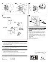
Wire the electrical connections
• Make sure the mains supply is isolated,
1. Wire the fan as shown in figure D check the fan model to diagram, feeding the
cable between the two raised pegs, if wiring from above, and through labyrinth to
terminal block.
2. Switch off the mains electrical supply and remove fuses
3. Connect the cable from the isolating switch to the electrical supply wiring.
• For fixed wiring circuits the protective fuse for the appliance must not exceed
5A.
DX100BT only – (fig. E)
• To adjust the over-run period turn the control (T) clockwise to increase and anti-
clockwise to decrease.
DX100BHT & DX100BHPT only – (fig. F)
The pre-set humidity operation is factory set at approximately 75% Relative Humidity
(RH), but can be adjusted between 65% and 85% RH by control H.
The over –run timer is factory set to approximately 20 mins, but can be adjusted
between 2 mins and 30 mins by control T.
Both controls are adjustable. Turn the controls clockwise to increase RH or time,
and anti-clockwise to decrease.
Using the fan
DX100B';%%3 only
• Operate the fan using the on/off switch. Repeat to switch off.
DX100BP only
• Operate the fan by pulling and releasing the cord. Repeat to switch off.
DX100BT only (fig. E)
• Operate the fan using an on/off switch. When the switch is turned off, the fan
continues to operate for the set time delay. To adjust the over-run period, turn the
control “T” clockwise to increase and anti-clockwise to decrease.
DX100BHT only
• The fan automatically adjusts to slow changes in natural humidity levels without
operating the fan. If the humidity levels increase at a rate slower than 5% RH in 5
minutes, up to the pre-set humidity level, the fan will not be triggered by humidity. This
is to prevent nuisance triggering of the fan. If humidity levels increase quicker than 5%
RH in 5 minutes the fan will operate. When relative humidity drops the fan continues to
operate for the adjustable time delay.
DX100BHPT only
• Automatic mode - The fan automatically adjusts to slow changes in natural humidity
levels without operating the fan. If the humidity levels increase at a rate slower than
5% RH in 5 minutes, up to the pre-set humidity level, the fan will not be triggered by
humidity. This is to prevent nuisance triggering of the fan. If humidity levels increase
quicker than 5% RH in 5 minutes the fan will operate. When relative humidity drops the
fan continues to operate for the adjustable time delay.
Manual mode – Use the integral pull cord switch. When the fan is switched off, it goes
into automatic mode after the time delay. Light indicates when the fan is operating in
manual mode.
Cleaning (This should be done by a qualified electrician)
1. Before cleaning, isolate the fan completely from the mains supply
2. Remove the front cover by pressing the release catches located on the sides of the
unit with a 3mm screwdriver, whilst pulling the front cover forward (fig. G).
3. To clean the front cover, either wipe it with a damp, lint free cloth or wash it with
warm soapy water. Thoroughly dry the front cover and refit.
4. Do not immerse the fan in water or other liquids to clean any other parts of the fan.
5. Do not use strong detergents, solvents or chemical cleaners
6. Allow fan to dry thoroughly before use.
7. Apart from cleaning, no other maintenance is required
Do’s and Don’ts
• Do read the entire instruction leaflet before commencing installation.
• Do install each fan with a means for disconnection in all poles in the fixed wiring.
• Do make sure the mains supply is switched off before attempting to make electrical
connections or carry out any maintenance or cleaning.
• Don’t install this fan in any window/panel, which is less than 3mm thick.
Guarantee
UK only:
We, Applied Energy Products Ltd., provide a guarantee against faulty parts and
manufacture for a period of 3 years from the date of purchase. In the unlikely
event of a product breakdown during the guarantee period the product should
be returned to the place of purchase or to Applied Energy Products Ltd.
Exclusions: This guarantee does not cover;
• Compensation for the loss of the product or consequential loss of any kind.
• Damage or defects to the product arising from incorrect installation.
• Transportation costs.
This guarantee does not affect your statutory rights
echnical advice and service
Customers outside UK - see international below.
UK: Xpelair have a comprehensive range of services including:
• Free technical advice help-desk from Engineers on all aspects of ventilation.
• Free design service, quotations and site surveys.
• Service and maintenance contracts to suit all requirements.
Please ask for details:
• By telephone on Techline: +44 (0) 844 372 7766
• By fax on Techfax: +44 (0) 844 372 7767
• At the address below
Head Office, UK Sales Office and Spares
Applied Energy Products Ltd, Morley Way, Peterborough, PE2 9JJ England
Telephone: +44 (0) 844 372 7761
Fax: +44 (0) 844 372 7762
Sales/Spares Hotline: +44 (0) 844 372 7750
Sales/Spares Faxline: +44 (0) 844 372 7760
www.xpelair.co.uk
International
• Guarantee: Contact your local distributor or Xpelair direct for details.
• Technical Advice and Service: Contact your local Xpelair distributor.
A4 Leaflet : Part No. 24216AA
(Revision A)
A
B
C
D
E
F
G
/