Page is loading ...

Simply SilentTM 100mm Contour Fan
Installation and Maintenance Instructions
C4SR (078339) Standard
C4TSR (078346) Timer
C4PSR (078353) Pull Cord
C4HTSR (078360) Humidistat, Timer
Do read the entire instruction leaflet before commencing installation.
Do install each fan with a means for disconnection in all poles in the fixed wiring.
Do make sure the mains supply is switched off before attempting to make electrical connections or carry out any
maintenance or cleaning.
Please leave this leaflet with the fan for the benefit of the user.

This appliance can be used by children aged from 8 years
and above and persons with reduced physical, sensory
capabilities or lack of experience and knowledge if they have
been given supervision or instruction concerning the use of
the appliance in a safe way and understand the hazards
involved. Children shall not play with the appliance.
Cleaning and maintenance of the appliance shall not be
made by children.
C4SR - Operate the fan using an on/off switch (not supplied).
C4PSR - Operate the fan using an integral pull-cord.
C4TSR* - Built-in timer operates fan for a preset delay from 30 seconds to 30 minutes.
C4HTSR* - Operates when triggered automatically by the integral humidity sensor, or by using an external
on/off switch (not supplied).
In automatic mode: the built-in timer automatically operates the fan for a pre-set delay time from
30 seconds to 30 minutes once humidity drops below the pre-set Relative Humidity (RH) value.
External operation: When switched off using the external on/off switch the fan continues to run for
the preset delay from 30 seconds to 30 minutes.
* Factory settings: Timer 15 minutes, RH 75%
Overall Dimensions (mm)
This appliance is intended for connection to fixed wiring.
Check that the electrical rating shown on each fan matches the mains supply.
THE APPLIANCE IS DOUBLE INSULATED AND DOES NOT REQUIRE AN EARTH CONNECTION.
All installations must be supervised by a qualified electrician. Installations and wiring must conform
to current IEE Regulations (UK), local or appropriate regulations (other countries).
All Xpelair Simply SilentTM Contour AC fans have the following features:
Two speed extraction (Selectable at installation)
Built-in back draught shutter
Replaceable Baffle. Fans are supplied with the Square Baffle fitted. This can be exchanged
with the spare Round Baffle supplied within the pack.

Back plate fixing positions
Wall tube quickfix clamps
Front Cover Removal
Depress Cover Latch with tool &
remove Cover and Baffle Complete
A
B
C
D
Minimum 30 seconds
Maximum 30 minutes
Factory settings: Timer 15 minutes, RH 75%
Break-outs
E
Front Cover and duct breakouts

Wiring and setting up
F
Square Baffle removal
Round Baffle fitting
G1
G2

Installation
If wall mounting the fan, you will also need:
A 100mm diameter prepared hole.
An appropriate external Wall Grille and Ø100mm wall sleeve duct. Kit Ref 91232AW.
If ceiling mounting the fan, you will also need:
A 100mm diameter prepared hole.
Appropriate ancillaries for termination. These items are available from Xpelair:
1. 3m flexible ducting Ref: 89663AA. If the duct passes through a cold space use insulated duct ref: 89847AA.
2. Soffit Grille Ref: 89742AW
3. XCT100 – Condensation Trap. Ref: 89749AA. Fitted immediately above the fan, this prevents water ingress due to
condensation forming in the duct above the fan and running down.
If surface mount wiring the fan, you will also need:
Miniature PVC trunking 16mm wide x 8mm deep to house the cable to the fan.
Installing the isolating switch and cables.
1. Check that the electrical rating shown inside the back-plate matches your mains supply.
2. Check there are no buried pipes or cables e.g. electricity, gas, water behind the switch location (in the wall or above
the ceiling). If in doubt, seek professional advice.
3. Isolate the mains supply.
4. Lay in the cable from the isolating switch to the fan location via the on/off switch (if required). This must be housed
in miniature PVC trunking.
5. Lay in the cable from the isolating switch to the point of connection to the mains supply.
6. Install the isolating switch and on/off switch (if required).
7. Make all connections within the isolating switch and the on/off switch (if required).
Where to locate the fan.
Locate it as high as possible.
At least 110mm from the edges of the mounting surface to the centre of the hole.
As far away as possible from and opposite to the main source of air replacement to ensure airflow across
the room (e.g. opposite the internal doorway).
Near the source of steam or odours.
Not where ambient temperatures are likely to exceed 50°C.
If installed in a kitchen fans must not be mounted immediately above a cooker hob, or eye level grill.
If installing in a room containing a fuel burning device which has a non-balanced flue, it is the
installer's responsibility to ensure that there is enough replacement air to prevent fumes being
drawn down the flue when the fan is operating up to maximum extract. Refer to Building Regulations
for specific requirements.
Exhaust air must not be discharged into a flue used for exhausting of fumes from appliances supplied
with energy other than electric. Requirements of all authorities concerned must be observed for
exhaust air discharge and intake flow rates.
Not suitable for use in possible chemical corrosive atmospheres.
Warning: Do not make any connections to the electrical supply at this stage.
What the installer will need.
3mm electrician’s screwdriver and No.1 or 2 Pozidrive screwdrivers.
A means for disconnection in all poles must be incorporated in the fixed wiring in accordance with wiring
regulations
If metal switch boxes are used, earthing regulations must be followed.
The cross-sectional area of the supply cord used should be ranged from 1-1.5mm².
C4SR / C4PSR – 2 core, C4TSR / C4HTSR – 3 core.
C4TSR / C4HTSR. A wall or ceiling On/Off switch (with indicator light) is recommended

For Australia Only - C4SR / C4PSR
Connection to the supply can be made by a flexible 2-core cable complete with 3 pin plug for insertion into an approved 10A
GPO or directly wired through an approved 10A wall mounted surface switch with at least 3mm clearance between contacts.
For Australia Only –C4TSR / C4HTSR
These models are permanently connected to the supply and operation is controlled by a remote switch. They should be directly
wired to the supply through an approved 10A wall mounted surface switch with at least 3mm clearance between contacts.
Preparing the Fan for installation.
1. Remove the front cover/baffle assembly by depressing the latch on the underside of the cover and pulling off the front
cover / baffle from the bottom (See Figure C).
Mark the position of the back-plate
2. Hold the back-plate so that the level line marked on it is orientated horizontally.
3. Carefully insert the fan tube into the wall duct.
4. Mark on the wall the positions of the fixing holes in the back-plate.
5. Remove the back plate from the ducting.
6. Drill screw holes in these positions if necessary, and fit wall plugs and screws as required. The fan may also be fixed
to a wall tube using the clamping brackets. See 9 below.
Mount the back-plate.
7. Feed the mains cable through the cable entry hole in the back plate to the terminals. If surface mount wiring ‘break
out’ the side wall in the duct flange for cable entry (See Figure E)
8. Insert the fan tube of the back-plate into the wall duct/ceiling as before.
9. Fasten the back-plate to the wall/ceiling using appropriate fasteners. See figure A.
10. If using screws, do not over tighten. The fan may also be fixed to a wall tube using the clamping brackets. Tighten the
screws until the fan is firmly secured to the tube – see figure B.
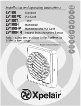
Wire the electrical connections.
11. Make sure the mains supply is isolated. Switch off the mains electrical supply and remove fuses.
12. Feed the cable to the terminal block. Wire the fan as shown in Figure H using the diagram appropriate to the fan
model.
13. Connect the cable from the isolating switch to the electrical supply wiring.
H
Wet Rooms: On/Off switch must be situated so that it cannot be touched by
persons making use of the bath or shower.
If working above ground floor level, safety precautions must be observed.
If installing in a ceiling, appropriate termination ancillaries are required. Follow
instructions provided.

Fan Settings.
SPEED SETTING
The fans are factory set to low speed, but have two speed settings for different applications. Select either high or low speed
by connecting the jumper between the centre and high or low speed pin on the jumper (see Figure F)
C4TSR Only.
To adjust the over-run period turn the control (T) clockwise to increase and anti-clockwise to decrease – see Figure D.
C4HTSR Only – see figures D and F.
The pre-set humidity operation is factory set at approximately 75% Relative Humidity (RH), but can be adjusted
between 65% and 85% RH by control H.
The over-run timer is factory set at 15 minutes but can be adjusted from 30 seconds to 30 minutes by control T.
Turn the controls clockwise to increase RH or time and anti-clockwise to decrease.
Using the fan.
C4SR Only
Operate the fan using the on/off switch (not supplied). Repeat to switch off.
C4PSR Only
Operate the fan by pulling and releasing the cord. Repeat to switch off.
C4TSR Only
Operate the fan using an on/off switch (not supplied). When the switch is turned off, the fan continues to operate for
the set time delay. To adjust the over-run period, turn the control “T” clockwise to increase and anti-clockwise to
decrease – see Figure F.
C4HTSR Only.
Automatic mode - The fan automatically adjusts to slow changes in natural humidity levels without operating the fan.
If the humidity levels increase at a rate slower than 5% RH in 5 minutes, up to the pre-set humidity level, the fan will
not be triggered by humidity. This is to prevent nuisance triggering of the fan. If humidity levels increase quicker than
5% RH in 5 minutes the fan will operate. When relative humidity drops the fan continues to operate for the adjustable
time delay.
External operation - Use the external on/off switch. When the fan is switched off, the fan continues to operate for
the adjustable time delay then goes into automatic mode.
All Fans
Re-fit the front cover/baffle assembly by hooking in the top first, and then swing the cover down to clip into place.
If surface mount wiring, ‘break out’ the thin wall section in the front cover prior to re-fitting (see figure E). The miniature PVC
trunking must then be sealed against the front cover to prevent any water ingress.
Replacing Square Baffle with Round Baffle (Figs. G1 and G2)
Ensure fan is isolated from supply before performing this action.
1. Remove Square Baffle/Cone assembly from Fan Front Cover by twisting anti-clockwise until all three support legs are
released from clips.
2. Fit Round Baffle/Cone assembly by aligning clips on baffle with legs on Front Cover and rotating Baffle Clockwise until
all three clips engage and are retained on Front Cover.
Cleaning (recommended once a month).
1. Before cleaning, isolate the fan completely from the mains supply.
2. Remove the front cover/baffle assembly by depressing the latch on the underside of the cover
and pulling off the front cover / baffle from the bottom.
3. To clean the front cover/baffle assembly, either wipe it with a damp, lint free cloth or wash it
with warm soapy water. Thoroughly dry the front cover and refit.
4. Do not immerse the fan in water or other liquids to clean any other parts of the fan.
5. Do not use strong detergents, solvents or chemical cleaners
6. Allow fan to dry thoroughly before use.
7. Apart from cleaning, no other maintenance is required.
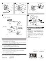
Important
For electrical products sold within the European Community. At the end of the electrical products useful life it
should not be disposed of with household waste. Please recycle where facilities exist. Check with a Local
Authority or retailer for recycling advice in your country. Batteries should be disposed of or recycled in
accordance with WEEE Directive 2012/19/EU. Packaging should be recycled where possible.

Warranty
What does an Xpelair Warranty cover?
Xpelair products deliver reliable service for normal, household use in domestic settings. All Xpelair products are individually tested before leaving the
factory.
If you are a consumer and you experience a problem with your Xpelair product, which is found to be defective due to faulty materials or workmanship
within the Warranty Period, this Xpelair Warranty will cover repair or - at the discretion of Xpelair – replacement with a functionally equivalent Xpelair
product.
The Xpelair Warranty Period is two calendar years from the date of purchase of your Xpelair product, or the date of delivery of the product, if later. The
Xpelair Warranty is conditional upon you providing the original purchase receipt as proof of purchase. Please therefore retain your receipt as proof of
purchase.
If you do experience a problem with your Xpelair product please call the Helpline on +44 [0]344 879 3588 or at the address below.
We will need details of your Xpelair product, and a description of the fault which has occurred. Once we receive your information and proof of purchase
we will contact you to make the necessary arrangements.
Customers outside UK – see international below.
If your Xpelair product is not covered by this Xpelair Warranty there may be a charge to repair your product. However, we will contact you for agreement
to any charges before any chargeable service is carried out.
What is not covered by an Xpelair Warranty?
The Xpelair Warranty does not cover any of the following:
• Any fault or damage to your Xpelair product due to faulty materials or workmanship occurring outside the two year Warranty Period.
• Any fault or damage occurring to any pre-owned Xpelair product or to any other equipment or property.
• Accidental damage to your Xpelair product or damage to your Xpelair product from external sources (for example, transit, weather, electrical outages or
power surges).
• Fault or damage to your Xpelair product which is:
• Not due to faulty materials or workmanship or which is due to circumstances outside Xpelair’s control.
• Caused by use of your Xpelair product for anything other than normal domestic household purposes in the country where it was purchased.
Important
• Caused by any misuse, abuse or negligent use of the Xpelair product, including but not limited to any failure to use it in accordance with the Operating
Instructions supplied with the product.
• Caused by any failure to assemble, install, clean and maintain your Xpelair product in accordance with the Operating Instructions supplied with the
product unless this was carried out by Xpelair or its authorised dealers.
• Caused by repairs or alterations to your Xpelair product not carried out by Xpelair service personnel or its authorised dealer(s).
• Caused by use of any consumables or spare parts for your Xpelair product which are not Xpelair specified.
Terms and Conditions
• The Xpelair Warranty is valid for Xpelair from the date of purchase of your Xpelair product from a recognised retailer in the country of purchase and use,
or the date of delivery of the product if later, always provided the original receipt has been retained and is produced as proof of purchase.
• You must provide to Xpelair or its authorised agents on request the original receipt as proof of purchase and - if required by Xpelair - proof of delivery. If
you are unable to provide this documentation, you will be required to pay for any repair work required.
• Any repair work under the Xpelair Warranty will be carried out by Xpelair or its authorised dealer(s) and any parts that are replaced will become the
property of Xpelair. Any repairs performed under the Xpelair Warranty will not extend the Warranty Period.
• Any replacement of your Xpelair product by Xpelair during the Warranty Period will start the two year Warranty Period afresh from the date of delivery of
the replacement Xpelair product to you.
• The Xpelair Warranty does not entitle you to recovery of any indirect or consequential loss or damage including but not limited to loss or damage to any
other property.
• The Xpelair Warranty is in addition to your statutory rights as a consumer and your statutory rights are not affected by this Xpelair Warranty.
Contact Xpelair
If you have any questions about what the Xpelair Warranty covers and does not cover or how to claim under the Xpelair Warranty, please contact us
using the information below.
Contact details
Millbrook House, Grange Drive, Hedge End, Southampton, SO30 2DF
Telephone: +44 (0) 344 879 3588
Email: customer.services@glendimplex.com
http:\\www.xpelair.co.uk
International.
Guarantee: Contact your local distributor or Xpelair direct for details.
Technical Advice and Service: Contact your local Xpelair distributor.
Xpelair: A brand of the GDC Group Limited, trading as Glen Dimplex Heating & Ventilation
© Glen Dimplex. All rights reserved. Material contained in this publication may not be reproduced in whole or in part, without prior permission in writing of
Glen Dimplex
Part No: 08/100114/0 (Rev A)
/