Page is loading ...

fold line fold line
fold line fold line
Sectional Handleset used with Keyless Entry Deadbolt
Installation Instructions
Congratulations! With your purchase of this Premium Entrance
Set, you’re among a group of discerning individuals who know the
intrinsic value of selecting the finest—Baldwin.
Our step-by-step installation instructions will help guide you
through your project quickly and easily.
Before you begin your installation, read and understand the
installation instructions and marking templates. If you have any
questions, please do not hesitate to contact our Baldwin Consumer
Help Line at 1-800-566-1986. We’re here to help! We thank
you for your purchase and wish you the fullest enjoyment of your
Baldwin product.
WARNING: Do not attempt to clean your hardware with any
type of abrasive cleaners, solvents, or chemicals. These types of
cleaning agents may mar the finish. A damp cloth is all that is
necessary to wipe clean.
Note: Finish Number 102, Oil-Rubbed Bronze, can be cleaned with
light machine oil and wiped with a dry cloth.
BEFORE YOU BEGIN
• This product does not contain deadbolt components
and is to be used with a Baldwin Keyless Entry
Deadbolt. Please refer to the Keyless Entry Deadbolt
product for installation instructions.
• Remove and discard all materials and screw(s) used for
packing your Premium Entrance Set. Verify that you have all
parts pictured on exploded view section of instructions.
• Follow the step-by-step sequence to ensure proper operation
of your Baldwin lockset.
• If your door is pre-drilled, skip Door Preparation.
• We recommend spreading cardboard over floor to prevent
scratching parts and marring floor.
• Always wear protective eye wear.
PK.9009 02/2010
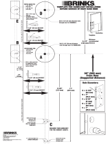
DOOR PREP
EXPLODED VIEW
Consumer Help Line
1-800-566-1986
Hours: 8 a.m. to 8 p.m. E.S.T. – Monday - Friday
10 a.m. to 6 p.m. E.S.T. – Saturday
If you have trouble installing your Baldwin product, feel free to call
our toll-free Consumer Help Line.
*Supplied with Keyless Entry Deadbolt product
EXTERIOR TRIM
1. Install latch (A) with latch screws (B). Predrill screw holes for
ease of installation using 1/8” bit.
2. Secure exterior subassembly (C) with retainer (D) and lower
pull screw (E).
ADJUSTING BACKSET
Grasp faceplate and rotate 180° for 2-3/4” backset.
A
B
C
D
E
fold line fold line
©2010 Baldwin Hardware Corporation, Lake Forest, CA 92610 PK.9009 (2/10)

©2010 Baldwin Hardware Corporation, Lake Forest, CA 92610 PK.9009 (2/10)
fold line fold line
fold line
fold line fold line
fold line
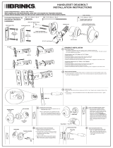
INTERIOR TRIM
WARRANTY INFORMATION
LIMITED LIFETIME MECHANICAL WARRANTY
Baldwin warrants that each Baldwin product shall be free from mechanical
defects at the time of delivery and for the lifetime of the product or as long
as you own your home.
LIMITED LIFETIME FINISH
™
WARRANTY
The Baldwin Lifetime Finish
™
uses advanced finishing technology (physical
vapor deposition) to create a finish highly resistant to the effects of weather and
normal wear and tear. The Limited Lifetime Finish Warranty on Lifetime Finish
™
products covers the original purchaser for as long as you own your home.
LIMITED FINISH WARRANTY
The finish on Baldwin products (excluding Lifetime Finish and living finish
products) is protected by a durable topcoat designed to maintain the beauty
and quality of the Baldwin product. The Baldwin Limited Finish Warranty
covers the original purchaser for five years from date of purchase for interior
use and one year for exterior use.
LIVING FINISHES
Due to the nature of Baldwin living finish products, they will wear over time
and may already have begun the process before reaching your home. No
finish warranty is offered on living finish products, which are designed to age
and improve over time. Living finishes include raw brass, oil rubbed bronze,
stainless steel, and other non-lacquered or non-PVD finishes.
REFER TO WWW.BALDWINHARDWARE.COM FOR A COMPLETE
WARRANTY STATEMENT.
TROUBLESHOOTING GUIDE
If parts are missing do not return product. Please call Baldwin’s
Consumer Help Line at 1-800-566-1986 and we will quickly send the
parts to you.
SCREWS ARE ALL TIGHT BUT THE HARDWARE IS NOT FIRMLY
ATTACHED TO THE DOOR.
Check door thickness. Door must be 1 - 3⁄4” thick. Hardware will not
install on doors less than 1 - 3⁄4” thick.
KNOB OR LEVER KEEPS COMING OFF THE SPINDLE.
Ensure that set screw on knob or lever is installed in V groove on
spindle and securely tightened with Allen wrench provided. Refer to
handleset installation step 5.
DOOR IS DIFFICULT TO LATCH OR WILL NOT STAY CLOSED.
Strikeplate is not aligning with latchbolt. Remove, plug holes with wooden
dowels and glue. Adjust and re-install. Condition can also be caused by
weather stripping being installed after hardware is installed. Re-install strike
as described at left. Refer to strikeplate installation step 1.
1. Place spindle (F) into latch (A) with the V-groove pointed to the hinge side of door (see view). Slide spacer (G) over spindle (F).
2. Install adaptor (H) over spindle (F) and secure with adaptor screws (J).
3. Test operation of handleset. If latch does not operate smoothly, loosen screws (E) and (J) and gently lift up the exterior subassembly
while retightening (J) screws. Test operation again.
4. Snap rose (K) onto adaptor. See alternate rose configuration when applicable.
5. Slide lever (L) onto spindle and secure with set screw (M) using supplied allen wrench (Q).
6. Tighten (E) screw and snap screw cover (P) over retainer (D).
7. Refer to PK.9008 for Keyless Entry Deadbolt installation.
F
A
G
H
J
K
L
N
P
Q
DOOR HINGE ALTERNATE ROSE CONFIGURATION
1. Place the rose (K) against
the door and thread the re-
tainer (R) onto the adaptor (H).
2. Securely tighten using
supplied spanner wrench (S).
K
R
S
Spindle V-groove
STRIKE INSTALLATION
1. Using the template mark PK.1182 the strike mounting holes and centering points.
2. Overlay strike and trace outline.
3. Mark (2) points, 5/16” above and below center point. Using a 1”
spade bit drill 1-1/4” deep at both points. Chisel out remaining material.
4. Predrill screw holes using 1/8” bit. Chisel outline of strike as shown.
5.Install dustbox (A) and strike (B) with strike screws (C).
C B A
/