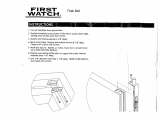
1. MARK DOOR
2. BORE FIVE (5) HOLES
Handleset
Lower
post
Square
Spindle
Horizontal
Posts
Copper Creek Handleset Installation Instructions
Read the instructions carfully before you begin installation. They provide important information on how to prepare your door and install your
handleset properly.
BEFORE PROCEEDING: TOOLS NOT INCLUDED BUT NEEDED FOR NEW INSTALLATION:
Check your door thickness. Be sure your door thickness is •
between 1-3/4” to 2”. (up to 2-1/4” if equiped with “thick door
kit)
Conrmthebacksetofyourdoortobeeither2-3/8”or2-3/4”.•
Match your Handleset latches backset with your backset on •
your door.
Phillips head screwdriver.•
Power Drill and 3/8” drill bit, 1” drill bit, 2-1/8” hole saw or drill bit.•
Hammer, and 1” Chisel..•
Backset
Deadbolt hole
center
Handleset hole
center
Lower thru-bolt
hole center
Height 36” to 38”
fromoor
5-1/2”
8-7/16”
Deadbolt
latch
hole center
Handleset
latch hole
center
Startapproximately36”to38”fromoor,1.
select backset, & apply template onto high
edge of bevelled door. Tape in place if
necessary.
Mark hole center on door face for deadbolt.2.
Mark hole center on door face for handle-3.
set.
Mark hole center on door face for lower 4.
thru bolt.
Mark hole center on door edge for deadbolt 5.
latch.
Mark hole center on door edge for handle-6.
set latch.
1. 2-1/8”
Hole
2. 2-1/8”
Hole
3. 3/8”
Hole
4. 1” Holes
Drill a 2-1/8” hole through the door face.1.
Note: it is recommended to rst drill a pilot
hole with 1/8” drill bit through the door, and
then drill the larger holes from both sides of
the door for steps 1, 2, and 3 to avoid splitting
and jagged edges.
Drill a second 2-1/8” hole through the door 2.
face.
Drill a 3/8” hole through the door face.3.
Drill two (2) 1” holes in the door edge.4.
3. MORTISE DOOR EDGE FOR LATCHES
Bevel
1.
3.
2.
Deadbolt
latch
Crank
Handleset
latch
Chisel 1/8” deep for latches to seat
ushwithdooredge
Insert Deadbolt latch into hole in door 1.
edge. Keep the latch face parallel & mark
an outline of latch face with pencil. Re-
move latch. Repeat for the handleset latch.
Chisel 1/8” mortise in door edge.2.
Insert latches into holes & tighten with 3.
wood screws.
Notes: Handleset latch bolt bevel must face
to the closing direction of the door.
Crank hole must be in the down position.
4a. MOUNT EXTERIOR HANDLESET
5. INSTALL STRIKES ON JAMB
Close door until latch bolt touches the 1.
door jamb. Mark the horizontal center
line along the latch face onto the jamb.
Measure one half of the door thickness 2.
from the door stop and mark vertical
center line onto the jamb.
Extend the horizontal center line and 3.
vertical center line, then mark the center
points for the strikes onto the jamb.
Place strikes in position and mark outline 4.
of strikes.
Horizontal
Center Line
Mark
Outline
of Strike
Plates
Drill a 1” hole, 1-1/8” deep in the door 1.
jamb at the upper center for the deadbolt
latch.
Drill a 1”hole. 9/16” deep in the door 2.
jamb at the lower center for the handle-
set latch.
Chisel outline for the strikes 1/16” deep 3.
oruntilstrikesareushwithdoorjamb.
Install the strikes and tighten wood 4.
screws.
1. 3.2.
6a. ADJUSTABLE LATCH FOR HANDLESET
Pull spindle cam all the way to right
edge of adjusting hole to move from
2-3/8” to 2-3/4” backset.
Note: Be sure to keep spindle cam square in cor-
rect position as illustratd before pushing spindle
cam in either direction. Other wise you will
havedifcultyinpushingspindlecamatall.
Adjusting
Hole
Spindle Cam
Sliding Plate
2-3/8” Post Hole
This Latch Is Set For 2-3/8”Backset
Sliding Plate
2-3/4” Post Hole
This Latch Is Set For 2-3/4”Backset
Spindle Cam
Spindle Cam
To re-set 2-3/8” backset
just push spindle cam to
left edge of adjusting hole.
Sliding Plate
Spindle Cam
Note: Most latches can be adjusted between either 2-3/8” or 2-3/4” backset. To adjust from
2-3/4 to 2-3/8” backset, follow the steps in the diagram below.
6b. ADJUSTABLE LATCH FOR DEADBOLT
Most models are equipped with a latch that can be 1.
adjusted between either 2-3/8” or 2-3/4” backset.
To adjust from 2-3/4 to 2-3/8” backset, hold the 2.
latch faceplate still and simply rotate the latch
body 180 degrees counter clockwise until it stops.
To adjust from 2-3/8” to 2-3/4” rotate latch body 3.
180 degrees clockwise until it stops.
Latch Face
Plate
Latch body
Locate horizontal posts and square 1.
spindle on inside of handleset, and lower
post.
Mount handleset on door inserting the 2.
posts and spindle through appropriate
hole in the latch.
Make sure lower post slide through 3/8” 3.
lower hole.
With 2 mounting screws, fasten interior 1.
knob or lever tirm to the handleset posts,
Leave loose for now.
Attach and tighten lower thru-bolt screw 2.
and washer to lower post.
Tighten two mounting screws3.
4b. MOUNT INTERIOR KNOB OR LEVER TRIM
4c. MOUNT DEADBOLT TRIM
For Single Cylinder Application:
Insert cylinder in decorative trim and press 1.
against door.. Make usre the tailpiece is
inserted horizontally through the latch cross
hair hole.
Slide inside turn-piece trim onto tailpiece and 2.
secure with machine screws.
For Double Cylinder Application:
Insert exterior cylinder in decorative trim 1.
and press against door. Make sure the tail-
piece inserted horizontally through the latch
crosshair hole.
Insert the interior clinder tailpiece verti-2.
cally through teh latch hole and secure with
machine screws.
Double Cylinder Exterior Trim
Interior Cylinder
Exterior Tailpiece
Inserted Horizontally
Interior Tailpiece
Inserted Vertically
Latch Crosshair Hole
Tailpiece
Tailpiece
Interior Turn-piece
Screw Holes
Machine
Screws
Single Cylinder Exterior Trim