Hitachi PC-ALHZ5Q Installation guide

Type
Installation guide

Hitachi PC-ALHZ5Q is a general control product compatible with Ducted Type indoor units such as PPIM-2.0~6.0UFA1NQ and PPIH-3.0~6.5UFA1NQ. It can be used to control up to 16 indoor units simultaneously, making it suitable for large room installations. The IR Receiver Kit features emergency operation buttons for cooling and heating, allowing for direct unit operation without a remote controller. Additionally, it has optional function settings for primary/secondary remote controller designation, adjacent unit setting modes, elevator griller control, and emergency operation enable/disable.

Hitachi PC-ALHZ5Q is a general control product compatible with Ducted Type indoor units such as PPIM-2.0~6.0UFA1NQ and PPIH-3.0~6.5UFA1NQ. It can be used to control up to 16 indoor units simultaneously, making it suitable for large room installations. The IR Receiver Kit features emergency operation buttons for cooling and heating, allowing for direct unit operation without a remote controller. Additionally, it has optional function settings for primary/secondary remote controller designation, adjacent unit setting modes, elevator griller control, and emergency operation enable/disable.

-1-
Operation & Installation Manual for IR Receiver Kit
Model: PC-ALHZ5Q
Please read this document in detail before installation.
Note: This document must be used in the following installation operations and therefore must be well
kept by the user.
(Handling and installation) (wiring) (trial running) (user)
Foreword
This product is a general control product, and its functions need support of the air conditioning system.
Please consult your dealer for further details.
When selecting the installation place, rst consideration shall be given to the convenience of users and
the place must be approved by the user.
Please do not install this product at the following places:
Places where there is oil splash (including mechanical oil) and vapor, and places where more
sulfide gases, such as hot springs, exist (which possibly results in fire and deforming, corroding and
damaging the product);
Coastal regions with high salt content, and alkaline or acidic environment (possibly result in the
product being corroded);
Places where children are accessible;
Humid places;
Places facing towards the air outlet of the air conditioner;
Places where there is much flying dust or dust;
Places under construction.
When using devices like certain medical equipment that produce electromagnetic waves, make sure
not to position the device in a way where the waves it creates are pointed directly at this product. This
helps prevent the device from malfunctioning.
Safety Summary
Please read this manual carefully before using the product and le it for future reference.
Aer installation, conduct trial running; aer conrming that there is no anomaly, please introduce the
operation and maintenance methods to the user and ask the user to keep the manual well.
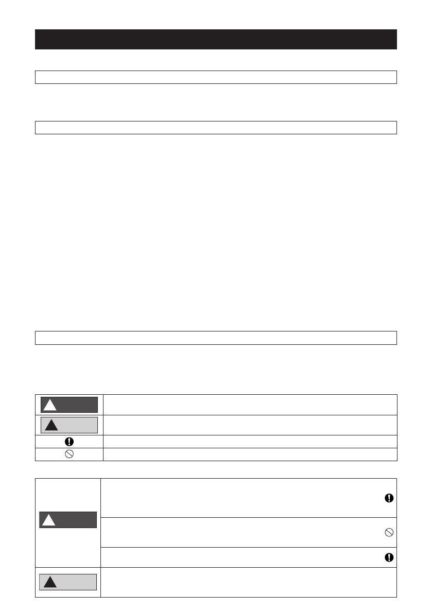
Signal Words
WARNING
!
Indicates a hazardous situation that, if not avoided, could result in death or serious
injury.
CAUTION
!
Indicates a hazardous situation
that
, if not avoided, could result in minor or moderate
injury.
Indicates a mandatory issue, instructing behaviors of non-specic general users.
Indicates a forbidden issue.
Installation
WARNING
!
Please install the product in strict accordance with this manual. Otherwise,
accidents such as electric shock, re and falling may happen.
Please install the product at the place capable of bearing its weight. Otherwise,
falling object may cause injury.
Please do not install the product at any place where combustible gas may be
generated or come in. Otherwise, accidents such as electric shock and re may
happen
.
Install the product only aer the power supply is disconnected. Otherwise,
electric shock may happen.
CAUTION
!
If the product with the IR Receiver Kit is interfered by external light source such
as uorescent lamp (frequency-varying uorescent lamp), it may not receive
wireless remote controller signals normally.
-2-
Electrical Installation
WARNING
!
The electrical installer shall have qualications for such activity. Please appoint
a qualied dealer to do the job. Otherwise, electric shock may happen.
During electric installation, please comply with applicable national standards
and the Instructions for Use and make sure a dedicated circuit is used.
Otherwise, accidents such as electric shock and re may happen.
Please use the required connecting cable. Otherwise, re and electric shock
may happen.
Cable shall be connected securely and rmly. Any loose connection may lead
to heated wires which may cause re and electric shock.
When the control board of the product or its related device must be taken out
due to electrical wiring and spot inspection etc., please completely disconnect
the power supply rst. Otherwise, electric shock may happen.
CAUTION
!The routing of communication cable shall not be in parallel with that of power
cable. Otherwise, it may generate interference causing malfunctions.
1. Compatible Indoor Unit Models
Types of indoor devices compatible with the IR Receiver Kit
Model of IR Receiver Kit Model of Compatible Indoor Unit
PC-ALHZ5Q Ducted Type PPIM-2.0~6.0UFA1NQ, PPIH-3.0~6.5UFA1NQ
CAUTION
!
Do NOT turn ON the power source, unless the preparation for test running is completed.
Read this manual carefully before installation work for correct performance.
Read this manual together with the instruction manual for the indoor unit and wireless remote controller.
2. Before Installation
Please conrm the following accessories are in the package before installation.
Name Q’ty Remarks
IR Receiver Kit 1 With Connection Cable
Band 1 For Fixing Wiring Cover and
Connecting Cable
Screw 4 For Fixing IR Receiver Kit
Screw 2 For Fixing Clamp
Clamp 2 For Fixing Cable
Operation and Installation Manual
(this manual) 1
-3-
3. Key Points for Installation
NOTES:
Install the IR Receiver Kit onto the wall or ceiling near the indoor unit.
Install the IR Receiver Kit and indoor unit at the same time.
In case that the IR Receiver Kit is installed aer installing the
indoor unit, turn OFF the power source of the indoor unit.
Check to ensure that the distance between the IR Receiver Kit
and the indoor unit is shorter than 5m.
Check to ensure that the distance between the IR Receiver Kit
and the EMI Source is larger than 3m.
Remove the cover by using slotted screwdriver.
Install the IR Receiver Kit onto the wall or ceiling as follows:
A. In Case of Exposing Cable B. In Case of Concealed Cable
(1) Fix the fixing bracket of kit by using screw (A) at 4
locations.
Screw (A)
(1) Prepare the following box (Field-Supplied).
JIS Box (JIS C 8336-1991)
1. Switch Box for 1 Controller
(Without Cover)
2. Small Switch Box for 1 Controller
(Without Cover)
3. Switch Box for 1 Controller
(With Cover)
Rigid Metal Conduit
Screw (M4) (Field-Supplied)
(2) Cut one of the knockout holes at the cover. (2) Insert the cable into the rigid metal conduit.
Cable
(3) Lead the cable though the groove and draw out
the cable from the knockout hole.
Band
Cable
Knockout Hole
(3) Fix the fixing bracket of kit by using screw (Field-
Supplied).
Cable
Screw (Field-Supplied)
This gure shows the case of Switch Box for 1
Controller.
(4) Attach the cover.
Do not clamp the cable when attaching the cover.
(Step 1)
Hooking Part
(Step 2)
Click Sound.
Fixing Bracket
Cover
(4) Attach the cover same as A-(4).
Box (Field-Supplied)
(Step 2)
Click Sound.
Check to ensure that
cable is not loosen.
(Step 1)
Hooking Part
Cover
Slot
Cover Holding
Bracket
-4-
Remove the cover of indoor unit electrical control box and connect the cable to the terminals A and B of
the terminal board (white).
NOTE:
Aer connecting the cable, bind up the remaining cable length portion by band (Factory-Supplied) and
put them in the electrical control box.
Printed Circuit Board
Te rminal block(TB1)
Mark Band "A"
Electrical Box
Te rminal block(TB2)
Cable for IR Receiver Kit
Mark Band "B"
for Indoor Unit
Example: PPIM-2.0UFA1NQ
4. Set the IR Receiver Kit
(1) Optional function setting
COOL
HEAT
1 2 3 4
ON
Dip Switch SW1
Factory-setting
HEAT Button
Case Base
(1) Remove the Base.
(2) Remove two screws
and open the case.
Printed
Circuit BoardCover
Hole for
Cable
COOL Button
Dip Switch SW2
Factory-setting
SIGNAL
IR Receiver Kit
Indicator Lamp
RUN
DEFROST
TIMER
FILTER
(2) Buttons “ ” and “ ” are for emergency operation. It is used for operating the unit directly without
using the wireless remote controller.
Button “ ”: Press “ ” to start cooling operation; Press “ ” again to stop.
Button “ ”: Press “ ” to start heating operation. Press “ ” again to stop.
NOTE:
During emergency operation, the yellow indicating light on the IR Receiver Kit is ashing in the cycle
of 0.5 second on/0.5 second o.
(3) The dip switch (DSW1 & DSW2) are optional for function setting and when needed, shall be set as per
the following requirements.
DSW1 1st digit Primary/Secondary setting
ON When using 2 remote controllers, set as secondary remote controller.
OFF When using 2 remote controllers, set as primary remote controller.
-5-
DSW1 2nd digit DSW1 3rd digit Adjacent unit setting mode
OFF OFF mode A
ON OFF mode B
OFF ON mode C
ON ON mode D
DSW1 4th digit Elevator griller setting
ON Elevator griller Up/Down is enabled.
OFF Elevator griller Up/Down is disabled.
DSW2 1st digit Emergency operation setting
ON Emergency operation is enabled
OFF Emergency operation is disabled.
DSW2 2nd digit Reserved
ON -
OFF -
5. Adjacent Unit Setting Mode
When two indoor units are set adjacently, sometimes,
both indoor units may receive signals from the wireless
remote controller simultaneously. To ensure both indoor
units operate properly, the IR Receiver Kit of one of
them may be set at the mode [adjacent unit setting]. For
example, for two indoor units A and B shown in the right
figure, set B at the mode [adjacent unit setting].
a. Method to set the adjacent unit setting mode
(1) Set the IR Receiver Kit
Set 2nd digit and 3rd digit of the dip switch (DSW1) on the IR Receiver Kit of the indoor device B (object
to be set) to another mode.
(2) Set the wireless remote controller
For setting, please refer to wireless remote controller’s Operation Manual.
b. Method to cancel the adjacent unit setting mode
(1) Set the IR Receiver Kit
The adjacent unit setting mode can be cancelled just by setting 2nd digit and 3rd digit of the dip
switch (DSW1) on the IR Receiver Kit to OFF.
(2) Set the wireless remote controller
For canceling, please refer to wireless remote controller’s Operation Manual.
6. About Simultaneous Control of Multiple Units
One IR Receiver Kit can be used to control simultaneously a number of indoor units (up to 16 devices).
When a number of indoor devices are installed in a large room, one single wireless remote controller can
be used to run and stop all these devices.
NOTE:
When a number of units are under simultaneous control, all their indoor devices shall be placed in the
same room. If using one wireless remote controller to control air conditioners in more than two rooms,
it is possible to forget to close one.
Indoor
unit A Indoor
unit B
The
indicator
is on
Set the wireless remote
controller at “adjacent
unit setting”
IR Receiver KitIR Receiver Kit
-6-
a. Set the IR Receiver Kit
In case of simultaneous operation of multiple (up to 16) indoor units by the wireless remote controller,
install the IR Receiver Kit only to the unit to be operated. Other units should be the standard units
without the IR Receiver Kit. If multiple IR Receiver Kits are required to install, 2 IR Receiver Kits are
available at a maximum.
b. Methods for wire connection and setting for the purpose of simultaneous control of multiple units
(1) Method to connect wires between indoor unit
Perform the connection work as following gure.
(2) The signal cable of all units shall not be in parallel with the power cable within the device and shall
be xed with wire buckle at key places. The distance between the signal cable and the power cable
shall be at least 30 mm outside the devices. Or, put the signal cable through the protective sleeve,
one end of which shall be grounded. When a shielded signal cable is used, one end of the shielding
net shall be grounded.
(3) Set addresses of all indoor devices.
7. Method for Test Running with the Wireless Remote Controller
Please test it in accordance with the wireless remote controller’s Operation Manual.
8. Alarm Code Indication
In case that some trouble occurs because of activation of safety device, etc., “ ” (red lamp) ashes
(0.5
second ON / 0.5 second OFF).
Refer to the Technical Catalogue of airCore 700 unit about Alarm Code List.
Alarm Code indicates the ashing times of “ ” (green lamp) and “ ” (yellow lamp) as shown below.
” (green lamp): The flashing is shown at the 2 digit of Alarm Code
” (yellow lamp): The flashing is shown at the 1 digit of Alarm Code
(Alphabet Code: A=10 times, B=11 times, C=12 times, .....)
Example
" " (yellow lamp)
Alarm
3 5
" " (green lamp)
" " flashes 3 times (0.5 second ON / 0.5 second OFF)
" " (yellow lamp) flashes 5 times (0.5 second ON / 0.5 second OFF)
” (red lamp) ashing (1 second ON / 1 second OFF) indicates abnormal transmitting between Indoor
Units and Outdoor Unit.
Wireless Remote Controller
Indoor Unit
with IR Receiver Kit
Standard
Indoor Unit
Standard Indoor Unit or
Indoor Unit with IR Receiver Kit
Should be Standard Indoor Units
Standard
Indoor Unit
Available to Install IR Receiver Kit
IR Receiver Kit Indoor Unit
Connect up to 16 indoor units
(Sub-wired remote controller
or IR Receiver Kit)
Indoor Unit
Terminal Block Terminal Block
(Twisted pair cable, 1P-Min.0.75mm2)
Memo
Hitachi-Johnson Controls Air Conditioning, Inc.
Add.: 1-16-1, Kaigan Minato-ku, Tokyo, Japan
Specification in this catalogue are subject to change without notice, in order that Hitachi-Johnson Controls
may bring the latest innovation to customers.
P02270Q 2023.09 V00 Printed in China
1201407 Scan the code to get the electronic manual.
  • Page 1 1
  • Page 2 2
  • Page 3 3
  • Page 4 4
  • Page 5 5
  • Page 6 6
  • Page 7 7
  • Page 8 8

Hitachi PC-ALHZ5Q Installation guide

Type
Installation guide

Hitachi PC-ALHZ5Q is a general control product compatible with Ducted Type indoor units such as PPIM-2.0~6.0UFA1NQ and PPIH-3.0~6.5UFA1NQ. It can be used to control up to 16 indoor units simultaneously, making it suitable for large room installations. The IR Receiver Kit features emergency operation buttons for cooling and heating, allowing for direct unit operation without a remote controller. Additionally, it has optional function settings for primary/secondary remote controller designation, adjacent unit setting modes, elevator griller control, and emergency operation enable/disable.

Ask a question and I''ll find the answer in the document

Finding information in a document is now easier with AI