Page is loading ...

SE-2800
DIGITAL VIDEO SWITCHER
( 8 / 12 CHANNEL )
Instruction Manual
www.datavideo.com

DIGITAL VIDEO SWITCHER
2
Standard Warranty
• Datavideo equipment is guaranteed against any
manufacturing defects for one year from the
date of purchase.
• The original purchase invoice or other
documentary evidence should be supplied at the
time of any request for repair under warranty.
• Damage caused by accident, misuse,
unauthorized repairs, sand, grit or water is not
covered by this warranty.
• All mail or transportation costs including
insurance are at the expense of the owner.
• All other claims of any nature are not covered.
• Cables & batteries are not covered under
warranty.
• Warranty only valid within the country or region
of purchase.
• Your statutory rights are not affected.
Warranty
Two Year Warranty
For EU Customers only - WEEE Marking
This symbol on the product indicates that it will not be treated as household waste. It
must be handed over to the applicable take back scheme for the recycling of electrical
and electronic equipment. For more detailed information about the recycling of this
product, please contact your local Datavideo ofce.
Disposal
Welcome to the SE-2800 Instruction Manual
Thank you for choosing a Datavideo product, please visit the support pages on
our website for the latest version of the instruction manual.
http://www.datavideo.info/Mixer+-+Switchers/SE-2800
Don’t forget to register your product online to qualify for an additional free
one year extension to the standard warranty, and to receive information from
Datavideo on service & information relevant to your Datavideo product including
new software updates & drivers
• All Datavideo products
purchased after 01-Oct.-
2008 qualify for a free
one year extension to
the standard Warranty, providing the product
is registered with Datavideo within 30 days of
purchase. For information on how to register
please visit www.datavideo.com or contact your
local Datavideo ofce or authorized Distributors
• Certain parts with limited lifetime expectancy
such as LCD Panels, DVD Drives, Hard Drives
are only covered for the rst 10,000 hours, or 1
year (whichever comes rst).
Any second year warranty claims must be
made to your local Datavideo office or one of
its authorized Distributors before the extended
warranty expires.

SE-2800
INSTRUCTION MANUAL
3
Contents
Welcome to the SE-2800 Instruction Manual 2
Warranty 2
Disposal 2
Warnings and Precautions 5
Packing List 6
Product Overview 6
Features 7
Connections & Controls 8
Control Panel Overview 8
Main Unit - Rear Panel 8
Rear Panel Connections 9
Main Unit - Rear Panel 10
HDMI Multi-view 11
How to change the Multi-view output 11
Keyboard Controls-Video Switching 12
Program and Preset rows 12
BG 12
SPEED 12
AUTO TAKE 12
CUT 12
FTB 12
T-Bar 12
Keyboard Controls-Video Transitions 13
Transition Selection 13
INV 13
MIX 13
Transition Conrmation 13
FIX / A+V 13
FREEZE 13
Keyboard Controls-LOGO 1, LOGO 2, CLOCK and TIMER 14
LOGO 1 14
LOGO 2 or CLOCK 14
TIMER 14
Keyboard Controls-PIP1, PIP2, DSK1 and DSK2 15
PIP Preset and PIP Program 15
Assigning a video source input to a PIP 15
DSK Preset and DSK Program 15
Assigning an input to a DSK channel for keying 15
Keyboard Controls-Frame Store, AUX and Audio level 16
FS – Frame Store Button 16
How to choose live video input or Frame Store 16
AUX Source Selection 16
Audio Level 16
Menu Options 17
SE-2800 Video Layers 19
PIP-Picture In Picture function 20
PIP Settings 20
PIP Preset and PIP Program 20
Assigning a video source input to a PIP 20
DSK function (CG / LUMA KEY) 21
DSK Settings 21
DSK Preset and DSK Program 21
Assigning an input to a DSK channel for keying 21
Example SE-2800 and CG-350 Set Up 22

DIGITAL VIDEO SWITCHER
4
Disclaimer of Product and Services
The information offered in this instruction manual is intended as a guide only. At all times, Datavideo Technologies will try to give correct, complete
and suitable information. However, Datavideo Technologies cannot exclude that some information in this manual, from time to time, may not
be correct or may be incomplete. This manual may contain typing errors, omissions or incorrect information. Datavideo Technologies always
recommend that you double check the information in this document for accuracy before making any purchase decision or using the product.
Datavideo Technologies is not responsible for any omissions or errors, or for any subsequent loss or damage caused by using the information
contained within this manual. Further advice on the content of this manual or on the product can be obtained by contacting your local Datavideo
Ofce or dealer.
How to obtain software or rmware for the SE-2800 22
Switcher conguration using a computer- SECong software 23
Proles 24
Switcher tab 24
Settings tab 24
Input settings tab 24
Multi screen window signs (labels) tab 25
Still pictures (FS) tab 25
Logos tab 25
Dynamic Logo tab 26
Multi screen A tab 26
Multi screen B+D tab 26
Multi screen C+E tab 26
Setting up with the SE Remote software 27
SET function 27
Controlling the switcher with a computer-SE Remote software 28
Software based Macro functions 28
REC & PLAY functions 28
TIME function 28
AUDIO function 29
Overview 29
Audio Menu Options – De-embedding SDI or HDMI audio 29
Audio Menu Options – Monitoring the audio levels 31
Audio Menu Options – Changing the audio input level 31
Changing the audio output level 31
Working with a xed or single audio source 32
Switching between different embedded audio sources 32
Audio Delay 33
Setting the Audio Delay 33
GPI / GPO Connections 33
SE-2800 Tally Outputs 34
How to obtain software or rmware for the SE-2800 35
How to update the SE-2800 Firmware 35
How to Re-calibrate the SE-2800 T-Bar 38
How to change the SE-2800 video standard 39
Example SE-2800 Set Up 41
Dimensions 41
Specications 42
Service & Support 44

SE-2800
INSTRUCTION MANUAL
5
Warnings and Precautions
1.Read all of these warnings and save them for
later reference.
2.Follow all warnings and instructions marked on
this unit.
3.Unplug this unit from the wall outlet before
cleaning. Do not use liquid or aerosol cleaners.
Use a slightly damp cloth for cleaning.
4.Do not use this unit in or near water.
5.Do not place this unit on an unstable surface,
cart, stand, or table. The unit may fall, causing
serious damage.
6.Any slots and openings on the case top, back,
and bottom are provided for ventilation. To
ensure safe and reliable operation of this unit,
and to protect it from overheating, do not block
or cover these openings. Do not place this unit
on a bed, sofa, rug, or similar surface, as the
ventilation openings may become blocked.
This unit should never be placed near or over
a heat source or radiator. This unit should not
be placed in a built-in installation unless proper
ventilation is provided.
7.This product should only be operated from the
type of power source indicated on the marking
label of the AC adapter. If you are not sure of the
type of power available, consult your Datavideo
dealer or your local power company.
8.Do not allow anything to rest on the power cord.
Do not locate this unit where the power cord will
be walked on, rolled over, damaged or otherwise
stressed.
9.If an extension cord must be used with this unit,
make sure that the total of the ampere ratings
on the products plugged into the extension cord
do not exceed the extension cord’s rating.
10.Make sure that the total amperes of all the
units that are plugged into a single wall outlet
do not exceed 15 amperes.
11.Never push objects of any kind into this unit
through the case ventilation slots, as they may
touch dangerous voltage points or short out
parts that could result in risk of re or electric
shock. Never spill liquid of any kind onto or into
this unit.
12.Except as specifically explained elsewhere
in this manual, do not attempt to service this
product yourself. Opening or removing covers
that are marked “Do Not Remove” may expose
you to dangerous voltage points or other risks,
and will void your warranty. Refer all service
issues to qualied service personnel.
13.Unplug this product from the wall outlet and
refer to qualified service personnel under the
following conditions:
a.When the power cord is damaged or frayed;
b.When liquid has spilled into the unit;
c.When the product has been exposed to rain
or water;
d.When the product does not operate normally
under normal operating conditions. Adjust
only those controls that are covered by the
operating instructions in this manual; improper
adjustment of other controls may result in
damage to the unit and may often require
extensive work by a qualified technician to
restore the unit to normal operation;
e.When the product has been dropped or the
case has been damaged;
f.When the product exhibits a distinct change in
performance, indicating a need for service.

DIGITAL VIDEO SWITCHER
6
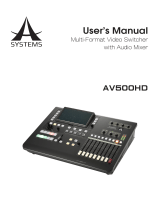
Packing List
Product Overview
The following items should be included in the box. If any items are missing please contact your
supplier.
*The accessory kit also contains a packing list.
The SE-2800 is a cost effective HD/SD switcher featuring eight* or twelve channels. Thanks to a
2RU 19” form factor and 12V DC input the SE-2800 is ideal for use in portable rack units or outside
broadcast vehicles. The SE-2800 produces superb 10 bit 4:2:2 broadcast quality pictures while also
offering exible input and output congurations. The SE-2800 also has powerful, easy to use effects,
such as dual picture in picture (PIP), downstream keyers (DSK) and logo insertion, as well as a clock
and multiple still image frame stores.
The SE-2800 has been designed for live productions such as concerts, conference, sports and worship
events as well as news and studio based programmes that may need to combine a number of video
sources with a mixed audio feed. The unit can also be congured and controlled over an Ethernet
network allowing even greater exibility and even more user set up options.
That’s Datavideo, sharing the value!
*Eight channel units can be upgraded to twelve at a later date
Please speak with your dealer for more information.
Item Description Qty
1 SE-2800 Switcher – Main Unit 1
2 SE-2800 Switcher – Control Panel 1
3 Instruction Manual 1
4 Accessory Kit* 1
HDMI
HDMI
SDI
SDI
HDMI
HDMI
圖文
系統
1
3
5
7
2
4
6
8
HD-SDI
HD-SDI
HD-SDI
HD-SDI
HD-SDI
HD-SDI
HD-SDI
HD-SDI
CAMERA
datavideo SE-2800
HD/SD 12
通道切換台
MULT-IMAGE PREVIEW
42” LCD TV/ MONITOR
42” LCD TV/ MONITOR
PREVIEW
TALLY
RS-232
INTERCOM
+TALLY
ITC-200 E
導播通話系統
擴充主機
PC
PC
AUDIO
IN
AUDIO
OUT
XLR XLR
SDI
SDI
VGA
SDI
LOOP SDI
HDMI
HDMI
HDMI
datavideo HDR-70
數位錄放影機
datavideo HDR-70
數位錄放影機
datavideo TLM-702HD
液晶螢幕監視器
datavideo TLM-700HD
7
吋螢幕監視器
VS-150
向量示波器
datavideo DAC-60
影像訊號轉換器
DAC-60
PROJECTOR
調音台
EXT.MIC
1
2
3
4
XLR
XLR
XLR
XLR

SE-2800
INSTRUCTION MANUAL
7
Features
■ The twelve input version can be congured as:
Twelve SDI or HD-SDI inputs,
Or Nine SDI or HD-SDI inputs with three HDMI
inputs,
Or Six composite inputs, with three SDI inputs
and three HDMI inputs
Or Six composite inputs, with six SDI inputs.
■ The eight input version* can be congured as:
Eight SDI or HD-SDI inputs,
Or Six SDI or HD-SDI inputs with two HDMI
inputs,
Or Four composite inputs, with two SDI inputs
and two HDMI inputs
Or Four composite inputs, with four SDI inputs.
■ HDMI based single or dual screen multi-view
outputs.
A choice from ve set ups, two with optional
HDMI Program output.
• Three user dened SDI or HD-SDI outputs.
Each of these outputs has the option to be:
Program output
Or Preview output
Or Program output without logo
Or Program output without logo and DSK
overlay
Or Aux output of a selected video input channel
(single Aux).
• User defined and positioned dual picture in
picture (PIP).
• Easy two step PIP source assignment using
keyboard.
• Two downstream keyers (DSK) with a set up
choice of basic Luma key or alpha channel.
• Easy two step DSK source assignment using
keyboard.
• User choice from seven stored logos for
insertion on preview and program outputs.
• One dynamic logo or moving image sequence.
File type can be TGA, GIF or AVI up to 75
frames long.
• Frame Store (FS) source for each input
channel. User can quickly toggle between a
pre-loaded still image and the connected live
source.
• On screen real-time clock featuring HH:MM only
– User dened position.
• User defined countdown timer for each input
shown within the HDMI Multi-view output.
• Six user defined wipe buttons - choice of 16
wipes with optional border.
• User can dene three speed buttons (in frames)
for selected transition when using Auto Take
button.
• T-Bar can be operated in one way or two way
mode.
• Choice of 8 full raster colour backgrounds or
SMPTE 75% bars for BG button.
• Up to four channels of audio can be embedded
on to the SDI and HDMI Program outputs.
Either from an external audio mixer (not
supplied) or selected HDMI, SDI and analogue
XLR inputs.
• Audio peak meters displayed on HDMI Multi-
view gives confidence of incoming and
outgoing audio.
• User choice for synch input and loop through –
composite black & burst or HD Tri-Level sync.
• SE-2800 can be configured over an Ethernet
network using a supplied Windows 7 PC
application.
• SE-2800 can be controlled remotely over an
Ethernet network using a supplied Windows 7
PC application.
• Low voltage Bi-colour Tally output on a single
25pin D-sub connector – compatible with other
Datavideo equipment or bespoke applications.
• GPI - Externally trigger transitions or devices
using the 3.5mm jack socket.
• XLR 12V DC input – Makes the unit ideal for
studio or OB van based applications.

DIGITAL VIDEO SWITCHER
8
Connections & Controls
Control Panel Overview
Main Unit - Rear Panel
AUDIO
LEVEL
MENU
PROGRAM
PRESET
WIPES
SPEED
PROGRAM
PRESET
1 2 3
4 5 6
F TB
BG7 8 9 10 11 12654321
BG7 8 9 10 11 12654321
321
LOGO
1
LOGO
2
CLOCK
ENTER
TIMER
AUTO
TAKE
CUT
PC
CTL
MIX
FREEZE
INV
PIP 1 PIP 2 DSK 1 DSK 2
PIP 1 PIP 2 DSK 1 DSK 2
FS
AUX
F I X
A I V
DC IN
12 V 48W
1 2 3 4 9 10 11 12
5 6 7 8
TALLY OUT
GPI
RS-422 REMOTE
AUDIO IN
CH1 CH2 CH3 CH4
AUDIO OUT
CH1 CH2
1
1
1
1
5
9
2
2
2
2
6
103
7
11 24 25
13 14 15 18 19 20 21 22 231716
4
8
12
3
3
3
4
4
4
5
5
5
6
6
6
7
7
7
8
8
8
9
9
9
10
10
10
19
11
11
11
20
12
12
12
21
13
13
13
22
14
14
14
23
15
24
16
25
17
18
** Please note inputs 9 to 12 are not present if you have purchased the eight channels SE-2800.
Eight channels unit can be upgraded to twelve inputs, please talk with your local dealer.
Frame Store button
Audio Level buttons
PC / Menu control
Transition selection
Logos 1 & 2, Clock & Timer
Input 1 – SD / HD-SDI / CVBS
Input 2 – SD / HD-SDI / CVBS
Input 3 – SD / HD-SDI
Input 4 – SD / HD-SDI / HDMI
Input 5 – SD / HD-SDI / CVBS
Input 6 – SD / HD-SDI / CVBS
Input 7 – SD / HD-SDI
Input 8 – SD / HD-SDI / HDMI
Input 9 – SD / HD-SDI / CVBS
Input 9 – SD / HD-SDI / CVBS
PIP selection PST & PGM
DSK selection PST & PGM
Speed Selection
AUTO TAKE
TB – Fade To Black
Input11 – SD / HD-SDI
Input12 – SD / HD-SDI
Connect the SE-2800 keyboard here
External Sync Input
User Dened SDI Outputs 1~3
Sync Output / Ref Loop
User Dened Multi view Outputs
Ethernet port for PC control & updates
Tally Output connector
GPI connector
CUT
T-Bar – Manual Transitions
Preset Row (PST)
Program Row (PGM)
RS-422 connector (not currently used)
4pin XLR Power Input
connector
Grounding Terminal
3pin XLR Audio Inputs
3pin XLR Audio Outputs
**
**
**
**

SE-2800
INSTRUCTION MANUAL
9
Rear Panel Connections
13 14 15 181716
1920x1080i
HD Inputs
HD-SDI
BNC
HDMI
1, 5 & 9 Yes ---
2, 6 & 10 Yes ---
3, 7 & 11 Yes ---
4, 8 & 12 Yes Yes
SD Inputs
CVBS
BNC
SDI
BNC
HDMI
1, 5 & 9 Yes Yes ---
2, 6 & 10 Yes Yes ---
3, 7 & 11 --- Yes ---
4, 8 & 12 --- Yes Yes
Video Input Modules
The SE-2800 can be supplied with eight or twelve video input
channels.
An SE-2800 with eight input channels has two video input
modules fitted. An SE-2800 with twelve input channels has
three video input modules fitted. An eight channel unit can
be upgraded to twelve inputs by adding another Video Input
Module.
There are four video input channels on each Video Input
Module. Each Video Input Module (shown top left) has the
same connections, four BNC connectors and one HDMI port.
The fourth BNC connector and the HDMI port are an option for
the same input channel.
The two tables, on the left, show which types of video inputs
can be connected to the SE-2800 switcher. For example, only
input channels 4, 8 and 12 have the HDMI input option.
NOTE: This switcher cannot accept 1080P or 1280x720P or
1440x1080i inputs and has no computer input scaling options.
To change the video standard see page 38.
SYNC I/O
The SE-2800 can be synchronised with other studio
equipment such as cameras and House sync. Input BNC
14
will accept House sync or Tri-level sync. Output BNC
16
can
be used to pass the sync signal to other studio equipment
such as cameras or recorders.
CONSOLE
This 9pin D-Sub connector
13
is used to connect the Control
Panel / Keyboard to the rear of the SE-2800 Main Processing
unit.
HDMI MULTIVIEW OUT
The SE-2800 has two HDMI outputs
17
which can be used
to display a preset combination of inputs plus program and
preset. See page 11 for the ve preset multi-view options.
SDI VIDEO OUTPUTS
The three BNC output connectors
15
are user defined SDI
outputs. Each of these SDI outputs has the option to be:
1. Program output
2. Preview output
3. Program output without logo
4. Program output without logo and DSK
5. Aux output of a selected input channel
SDI outputs 2 and 3 also have the option to be a Program
output which has been downscaled from HD to SD resolution.
ETHERNET PORT
This RJ45 Ethernet port
18
is used to connect the SE-2800 to
a PC for remote control, or to update the unit’s rmware, or to
congure the switcher. See page 23 for more details.

DIGITAL VIDEO SWITCHER
10
AUDIO OUT
Supports two channels XLR Balanced Audio output.
See page 29 for more details.
AUDIO IN
Supports four channels XLR Balanced Audio Input.
See page 29 for more details.
TALLY OUT
The SE-2800 Tally Output port provides bi-colour tally
information to a number of other Datavideo products, such as
the ITC-100 eight channel talkback system or the Datavideo
TLM range of monitors. See page 34 for more details.
GPI
The GPI socket can be used for simple external control.
See page 33 for more details.
RS-422 REMOTE
This feature is not currently active. A firmware update may
be released at a later date. Please check with your local
Datavideo ofce for advice on this connection and the latest
rmware.
DC IN
Connect the supplied 12V 5A PSU to this 4pin XLR socket.
Pin 1 = GND ( - )
Pin 2 = NC
Pin 3 = NC
Pin 4 = VCC ( + )
Grounding Terminal
When connecting this unit to any other component, make sure
that it is properly grounded by connecting this terminal to an
appropriate point. When connecting, use the socket and be
sure to use wire with a cross-sectional area of at least 1.0 mm.
The front panel on the SE-2800 main unit has a grille for two airow cooling fans. Please do not block
or cover this grille as the unit may overheat. This grille should also be kept free of dust. The front panel
can be removed by using the four thumbscrews. A soft brush or cloth can then be used to clean the
grille before attaching it back to the unit.
The power button starts and shuts down both the SE-2800 main unit and its attached keyboard.
AUDIO OUT
CH1 CH2
AUDIO IN
CH1 CH2 CH3 CH4
TALLY OUT
GPI
DC IN
12 V 48W
RS-422 REMOTE
1
23
4
Main Unit - Rear Panel
POWER
DIGITAL VIDEO SWITCHER
SE-2800

SE-2800
INSTRUCTION MANUAL
11
SE-2800 Multi-view monitoring is available across one or two HDMI monitors (not supplied). These HDMI outputs
can be used to monitor video and audio in a number of different congurations. For each set up, embedded audio
level indication is also available on all inputs as well as the Preview and Program windows.
This Multi-view is supplied from the HDMI connection(s) on the rear panel. (See page 8, Rear Panel, item 17.)
When connected to two compatible HDMI monitors a variety of multi-image layouts is possible.
Conguration A:
■
On HDMI screen 1: 9 live inputs
■
On HDMI screen 2: 3 live inputs with additional Preview and Program windows
Conguration B:
■
On HDMI screen 1: 12 live inputs with additional Preview and Program windows
■
On HDMI screen 2: Program window
Conguration C:
■
On HDMI screen 1: 8 live inputs with additional Preview and Program windows
■
On HDMI screen 2: Program window
Conguration D:
■
On HDMI screen 1: 12 live inputs with additional Preview and Program windows
■
On HDMI screen 2: Same as HDMI screen 1
Conguration E:
■
On HDMI screen 1: 8 live inputs with additional Preview and Program windows
■
On HDMI screen 2: Same as HDMI screen 1
HDMI Multi-view
A
HTMI1 HTMI2
PST PGM
B
PROGRAM
C
PST PGM
E
PST PGM PST PGM
PROGRAM
PST PGM
D
PST PGM PST PGM
Shown left are the five multi-view configuration
options A to E.
How to change the Multi-view output
To change the multi-view option on your switcher
press the ENTER button in the MENU area of
the SE-2800 Control Panel / Keyboard. This will
display an on screen menu on HDMI output 1.
Then use the arrow down button to highlight the
option Multi Screen Mode. Use the arrow keys
to highlight your preferred option from those
shown on the left. Use the arrow keys to place a
tick in the selection box and then press ENTER to
save this choice.
On screen Tally indication
The SE-2800 Multi-Image Preview supplies basic
tally information by highlighting the live Program
input source with a red border, and the cued next
input source with a yellow border.
Function Area
Below the Program and Preset image windows
is a function area occupied by a real time Clock,
Countdown Timer (if active), chosen Wipe
indicator, PC or Console control indication and
chosen Audio mix and Audio level indicators.
Labels
Below each video input channel window there
is a label. These labels can be edited using the
software supplied with the SE-2800, see page 23
for more details.

DIGITAL VIDEO SWITCHER
12
Keyboard Controls-Video Switching
Program and Preset rows
BG
The Program row of buttons is the active channel, this is the live output. The active channel will appear
as the Program Output (PGM). You can switch or CUT from one video source to another directly on
the Program row. You will see the multi view PGM output change as you press different keys along this
top row of buttons.
Background button – assigns a background colour or SMPTE 75% bars for use on the Program and
Preset row.
The Preset row is the cued channel, this channel will appear in the PST or Preview window. The
Preset row selection decides which input will be transitioned next when using any of the transition
controls.
N.B. The keys on the Program and Preset rows will be inactive while the T-Bar is active or
moving. Only when the T-Bar is fully up or fully down will the keys respond.
PROGRAM
PRESET
BG7 8 9 10 11 12654321
BG7 8 9 10 11 12654321
321
SPEED
AUTO
TAKE
CUT
F TB
SPEED
There are three speed buttons which can be defined by the
user. By pressing a speed button the user is choosing the rate
of transition or time taken when using the AUTO TAKE button.
AUTO TAKE
This performs an automated switch from the current program
source to the selected preset source. The selected transition
wipe or dissolve will also be used. The timing of the transition
is set by the chosen Speed button.
CUT
This performs a simple immediate switch from the current
main source to the selected sub source. The selected
transition wipe or dissolve is not used.
FTB
Fade To Black, this button fades the current video program
source to black. When pressed again it acts in reverse from
complete black to the currently selected program video
source.
T-Bar
This performs a manually controlled transition from the current
program source to the selected preset source. The selected transition
wipe or dissolve will be used. When the T-Bar has travelled as far as
it can go the transition between sources is complete. The T-Bar has
indicators next to it which light when the transition is complete.
The T-Bar can be operated in one of two modes which is chosen by a
menu option, see page 17 onwards for more details.

SE-2800
INSTRUCTION MANUAL
13
Keyboard Controls-Video Transitions
Transition Selection
The SE-2800 features six user dened wipe buttons, an
A/B dissolve or MIX button, an INV or Invert wipes button
and a FREEZE button.
All wipes can have an optional colour border applied. The
wipe border width and colour are chosen within the menu
system.
Transitions can be performed manually using the T-Bar
or automatically by using the SPEED and AUTO TAKE
buttons.
WIPES
1 2 3
4 5 6
MIX
FREEZE
INV
F I X
A I V
INV
F I X
A I V
F I X
A I V
FREEZE
INV
Invert the selected wipe so it
travels in the opposite direction.
Transition Conrmation
The selected transition is highlighted in the status area
of the HDMI multi-view output. When the INV button
is pressed the six wipe icons change to their opposite
direction icon.
MIX
Pressing this button selects a basic
A/B Dissolve for the next transition.
FIX / A+V
Switch the audio mixing selection
between Audio Fixed and Audio-
Follow-Video (A+V).
FREEZE
Freeze the program source image
or return to live video of the selected
program source.
Vertical Wipe Left to
Right.
Vertical Wipe Right to
Left.
Horizontal Wipe Bottom to
Top.
Horizontal Wipe Top to
Bottom.
Vertical Wipes from
Centre to Left and Right
sides.
Vertical Wipes from Left
and Right sides to Centre.
Horizontal Wipes from
Centre to Top and Bottom.
Horizontal Wipes from Top
and Bottom to Centre.
Circle Wipe from Centre
to outside edges.
Circle Wipe from outside
edges to Centre.
Diamond Wipe from
Centre to outside edges.
Diamond Wipe from
outside edges to Centre.
Box Wipe from Centre to
outside edges.
Box Wipe from outside
edges to Centre.
Diagonal wipe from upper
left to lower right.
Diagonal wipe from lower
right to upper left.

DIGITAL VIDEO SWITCHER
14
Keyboard Controls-LOGO 1, LOGO 2, CLOCK
and TIMER
The SE-2800 has the ability to store six static logos and one dynamic logo.
The logo les are transferred to the SE-2800 from a Windows PC using the
Ethernet connection and the supplied SECong software. See page 23 for
more details on using this software.
LOGO 1
The LOGO 1 and LOGO 2 buttons are used to display pre-selected logos
on the SE-2800 Preset and Program outputs. When the button is active
the selected logo is shown. These logos are selected from the switcher’s
memory and positioned using a menu option see page 17 for details.
LOGO 2 or CLOCK
The user cannot display LOGO 2 and CLOCK at the same time. Instead use
LOGO 1 and CLOCK together or use LOGO 1 and LOGO 2 together.
The clock time can be synchronised with a computer or set manually using
a menu option. The colour and font used in the clock digits can be changed
using the supplied SEConfig software. See page 23 for more details on
using this software or see page 17 onwards for the Clock menu options.
TIMER
In some mixing or switching applications it is useful to have a countdown
timer. It could be that the input is a pre-recorded video clip and you need to
know when to be ready to switch away from it.
This countdown timer function is only seen in the status area of the HDMI
multi-view output to the right of the normal Clock function. The timer can be
selected for one input channel, several channels or all channels.
When the TIMER button is active and the user switches to a selected input
channel the countdown starts on the HDMI multi-view.
The value of the countdown, in minutes and seconds (MM:SS), is set by a
menu option. Whilst the countdown is in progress T-Bar operation is ignored.
When the countdown reaches zero the user can then switch or transition to
another input channel. If the countdown reaches zero the switcher will not
automatically change to the selected Preset source.
LOGO
1
LOGO
2
CLOCKTIMER

SE-2800
INSTRUCTION MANUAL
15
Keyboard Controls-PIP1, PIP2, DSK1 and DSK2
PIP Preset and PIP Program
When looking at the top right corner of the SE-2800 Control Panel /
Keyboard there are four PIP keys. These are labelled Program and Preset.
The upper PIP1 and PIP2 keys relate to activating Picture In Picture images
on the Program outputs. The lower PIP1 and PIP2 keys relate to activating
Picture In Picture images on the Multi-view or Preview outputs.
Assigning a video source input to a PIP
Using the lower PIP1 or PIP2 buttons you can assign a selected video input
to the chosen PIP video layer.
1) First press and hold down the required PIP button on the lower row. The
Preset row of input sources will light.
2) While still holding down the PIP button, press to select the required input
from the Preset row.
3) The input will ash to conrm it is selected.
This selection will also be conrmed on the HDMI Multi-view, with a P1 or
P2 label shown next to the selected input image.
The full PIP process is described on page 22.
DSK Preset and DSK Program
When looking at the top right corner of the SE-2800 Control Panel /
Keyboard there are four DSK keys. These are labelled Program and Preset.
The upper DSK1 and DSK2 keys relate to activating Down Stream Keying
on the Program outputs. The lower DSK1 and DSK2 keys relate to activating
Down Stream Keying on the Multi-view or Preview outputs.
Assigning an input to a DSK channel for keying
Using the lower DSK1 or DSK2 buttons you can assign a selected video
input to the chosen DSK video layer.
1. First press and hold down the required DSK button on the lower row. The
Preset row of input sources will light.
2. While still holding down the DSK button, press to select the required
input from the Preset row.
3. The input will ash to conrm it is selected.
This selection will also be conrmed on the HDMI Multi-view, with a T1 or T2
label shown next to the selected input image.
The full DSK process is described on page 21.
PIP 1 PIP 2
PIP 1 PIP 2
DSK 1 DSK 2
DSK 1 DSK 2

DIGITAL VIDEO SWITCHER
16
Keyboard Controls-Frame Store, AUX and
Audio level
FS – Frame Store Button
The SE-2800 has eight or twelve video channels, depending on the number
of inputs it has. Each of these channels has its own Frame Store, making a
total of eight or twelve Frame Stores. Each of these Frame Stores can hold
one still image. This still image can be called into the production by using
the FS button located at the top left corner of the SE-2800 Control Panel /
Keyboard. The FS button allows the user to toggle between the still image
of the Frame Store or the live video input also connected to that same video
channel.
How to choose live video input or Frame Store
1. First press and hold down the FS button. The Preset row of input sources
will light.
2. While still holding down the FS button, press the required input on the
Preset row.
3. The input button will ash to conrm the Frame Store is selected.
This selection will also be confirmed on the HDMI Multi-view, with the
selected channel showing the live input or frame store image.
The contents of each Frame Store is uploaded to the SE-2800 from a PC.
The supplied SECong software is used to do this. The le upload process
is described on page 23.
AUX Source Selection
The SE-2800 has three user dened SDI outputs, see page 9 item 15. One
or all of these outputs can be set up as an auxiliary (AUX) output via a menu
option. See page 17 onwards for details.
The AUX output source can be quickly selected in the following way.
1. First press and hold down the AUX button. The Preset row of input
sources will light.
2. While still holding down the AUX button, press the required input on the
Preset row.
3. The input button will ash to conrm the AUX source is selected.
This selection will also be confirmed by the SD/HD-SDI Monitor supplied
with these AUX images.
Audio Level
The SE-2800 has ability to do a basic mix/switch of analogue, SDI and
HDMI embedded audio, see page 29 for details.
The AUDIO LEVEL buttons are related to the level of the Program audio
output, whether SDI embedded or analogue XLR.
FS
AUX
AUDIO
LEVEL

SE-2800
INSTRUCTION MANUAL
17
Menu Options
When the ENTER button is pressed the Main Menu list is displayed on the
HDMI 1 Multi-view output.
This section covers the Menu options in the order that they appear on the
SE-2800 HDMI 1 Multi-view. These settings may also appear in more detail
elsewhere in this instruction manual. Options may vary depending on the
rmware version in use.
Once the chosen setting has been confirmed with the ENTER button it is
stored within the switchers non-volatile memory.
MENU
ENTER
PC
CTL
Version Number V.xx.xx - where xx.xx is the rmware version number
Input Video Settings
Select the input that you want to
adjust in the PVW window.
This is a ne adjustment, the
change happens gradually
as the value is increased or
reduced.
Brightness
Contrast
Saturation
Aperture
Y-C Delay
Set To Nominal
Range 72 to 184, default 128
Range 36 to 92, default 64
Range 36 to 92, default 64
Not used in current rmware
Not used in current rmware
Reset to default values
Inputs Standard and Format
Inputs 1,2,5,6,9 &10 Can be a choice of HD SDI*
SD SDI 4:3
SD SDI 16:9
CVBS 4:3
CVBS 16:9
Inputs 3,7 &11 Can be a choice of HD SDI*
SD SDI 4:3
SD SDI 16:9
Inputs 4,8 &12 Can be a choice of HD SDI*
SD SDI 4:3
SD SDI 16:9
or
HDMI*
HDMI SD 4:3
HDMI SD 16:9
*All HD inputs are natively 16:9 aspect.
Input Audio Settings
Level
Nominal
Range -60 to +60
Resets value to zero
SDI Embedded Audio Set. Inputs 1 to 12 User choice of
Group 1,2,3 or 4
Pair 1 or 2
HDMI in Embedded Audio Pair Input 4,8 or 12 User choice of Group 1,2,3 or 4
Outputs Emb Audio Group Outputs 1,2 or 3 User choice of Group 1,2,3 or 4
Auto Audio Mixing Type User choice of
X type or V type
Tick selection
X type = A/B cross fade
V type = Fade out A then Fade in B
T-Bar Audio Mixing Type Tick selection of
Follow auto audio mixing type (use above option)
By the end (clean cut or immediate audio switch)
PIP Settings
Position PIP1
Size PIP1
Border PIP1
Position PIP2
Size PIP2
Border PIP
X-Position (Left to right) = 000 to 097
Y-Position (Lower to Upper) = 000 to 108
PIP Size = 1 (small) to 33 (large)
Border Size = 0 (OFF), 1 (Thin) to 15 (Thick)
Border Color = 1 to 8 (user dened colours)
1=White, 2=Yellow, 3=Cyan, 4=Green, 5=Magenta, 6=Red, 7=Blue,
8=Black
LOGO Setting
Logo1
Logo2
X-Position (Left to right) = 000 to 110
Y-Position (Lower to Upper) = 000 to 135
Selection = 1 to 8
Logo selection 1 to 7 are still image
Logo 8 selection is dynamic moving image

DIGITAL VIDEO SWITCHER
18
Speed Buttons Setting
Speed1
Speed2
Speed3
Range 1 to 127 (Frames)
Wipe Buttons Setting Buttons 1 to 6
Wipe 1 to 8 (See page 13 also)
Soft Edge 0 to 4
Color 1 to 8
1=White, 2=Yellow, 3=Cyan, 4=Green, 5=Magenta, 6=Red, 7=Blue,
8=Black
Outputs Mode
OUT 1 is an HD SDI only user choice of Program
Program Logo Free
Program Logo & Titles Free
Preview
Aux
OUT 2 user choice of Standard & Format HD SDI
SD SDI 4:3
SD SDI 16:9
Plus MODE choice of Program
Program Logo Free
Program Logo & Titles Free
Preview
Aux
OUT 3 has the same user choices as OUT 2
DSK Settings
Titles 1
Titles 2
Titles + a-CH mode (alpha channel)
Luma Key mode
Luma Key Level 0 (black) to 255 (white)
BG Color Setting
User choice of background colour from 1 to 9
1=White, 2=Yellow, 3=Cyan, 4=Green, 5=Magenta, 6=Red, 7=Blue, 8=Black,
9 = SMPTE 75% colour bars
T-Bar Mode
One Way Mode
Two Way Mode
= T-Bar operates transition in only one direction
= T-Bar operates transition in both directions
1kHz to Bars
When BG Color Setting option above = 9
1kHz tone can be ON or OFF depending on tick selection
Keys Brightness
User choice of 1 to 4
Brightness of keyboard buttons, 1= Low, 4= High
Keys Mode Tick selection ON or OFF, ON=Active buttons are Red, OFF=Green is Active
Audio Level is shown Tick selection ON or OFF, ON=Audio Peak Meters shown on HDMI Multi-view
Reference
External Tick selection for ON or OFF
Mode Choice of HD Analog 3 Level Signal
Or SD Composite PAL/NTSC
H-Timing Zero to 15
Aux
The value shown here relates to the selected input – See page 16 also.
This setting is also related to the Outputs Mode on page 17.
Factory Settings Tick selection ON or OFF, ON= Reset all settings to their default values.
Clock Settings
X-Position (Left to right) = 000 to 110
Y-Position (Lower to Upper) = 000 to 135
Set Hours
Set Minutes
Clear Seconds
Multi Screen Mode
This selection relates to the HDMI outputs 1 (=W1) and 2 (=W2).
A : W1 = PGM + PVW + 3 IN ; W2 = 9 IN
B : W1 = PGM + PVW + 12 IN ; W2 = PGM
C : W1 = PGM + PVW + 8 IN ; W2 = PGM
D : W1 = PGM + PVW + 12 IN ; W2 = W1
E : W1 = PGM + PVW + 8 IN ; W2 = W1
See page 11 also.
GPI Settings
Input Select = Chosen input number
Time Delay = In frames between 1 to 75
Countdown Timer Settings
Each input can selected for Count Down ON or OFF.
If Count Down is ON then the Down Counter value is set in minutes and seconds (MM:SS)
- Max.= 1 Hour or 60:00, Default = 15 Seconds or 00:15
Audio Associations
Input channels 1-12, Value 1-12
( used to choose an embedded audio source – see page 29 onwards for more details )
Multi Screen Audio Tick selection of Program or Preview audio on the HDMI outputs.

SE-2800
INSTRUCTION MANUAL
19
SE-2800 Video Layers
The SE-2800 is a Standard Definition or High
Definition Digital Video Switcher and as well as
mixing video and audio sources it has additional
functions such as Picture In Picture (PIP), DSK
LUMA KEY and LOGOs.
The Background video layer is the normal video
layer when mixing and switching with the SE-
2800. It occupies the whole screen area of the
Program output. This layer can be hidden or part
hidden by the PIP, DSK and LOGO layers in front
of it.
The PIP 1 layer does not occupy the whole
screen and is shown in front of the Background
video layer when enabled. In some setups the PIP
1 image can be hidden behind the PIP 2 image.
This is not a fault. Change the position or size of
the PIP 1 or PIP 2 image if required.
The PIP 2 layer does not occupy the whole
screen and is shown in front of the Background
video and PIP 1 layers when enabled. In some
setups the PIP 1 image can hide the PIP 2 image.
Change the position or size of the PIP 2 or PIP 1
image if required.
The DSK 1 layer can occupy the whole screen.
If set up incorrectly this layer can stop the video
layers behind it from being seen properly. Re-
adjust your DSK 1 settings or switch off the DSK1
function on the SE-2800 to restore the video
behind it.
Background Video & Wipes
PIP 1
PIP 2
DSK 1
DSK 2
LOGO 1, LOGO 2 or CLOCK
The DSK 2 layer can occupy the whole screen.
If set up incorrectly this layer can stop the video
layers behind it from being seen properly. Re-
adjust your DSK 2 settings or switch off the DSK1
function on the SE-2800 to restore the video
behind it.
The LOGO and Clock layer does not occupy
the whole screen and all other layers are visible
through it. A logo if positioned incorrectly can
partially hide an important part of the video, PIP or
CG LUMA KEY layers. Typically logos or station
ID bugs are placed in a corner of the screen.
N.B.: Where possible prepare and position the
upper video layer elements in advance of the live
production starting to avoid them appearing on
the program output incorrectly.
Most broadcast networks have guidelines and
advice on the use of video, images, music,
logos and on screen text so it is best to check
beforehand when planning a production. Do not
use copyright protected content until you have
the relevant permissions. Information on royalty
free video, images and music is widely available,
speak to your local dealer or search for advice on
the internet.
Before attempting to use the SE-2800’s PIP, DSK
LUMA KEY and LOGO functions it may help to
first understand the order of the video layers at
the SE-2800 Program (PGM) outputs.

DIGITAL VIDEO SWITCHER
20
PIP-Picture In Picture function
The SE-2800 Picture in Picture function allows
you to place one or two smaller PIP images over
a chosen full size background image. The smaller
PIP images can be set to pre-defined sizes and
positioned almost anywhere within the Preview/
Before trying to activate the PIP function it is best to understand how to set up or choose the right
options for your production. Press the ENTER Key in the MENU area of the SE-2800 keyboard.
Navigate to the PIP Settings option using the down arrow key. The PIP menu options provided here
are:
PIP Settings
PIP Settings
Position PIP1
Size PIP1
Border PIP1
Position PIP2
Size PIP2
Border PIP
X-Position (Left to right) = 000 to 097
Y-Position (Lower to Upper) = 000 to 108
PIP Size = 1 (small) to 33 (large)
Border Size = 0 (OFF), 1 (Thin) to 15 (Thick)
Border Color = 1 to 8 (user dened colours)
1=Yellow, 2=Cyan, 3=Green, 4=Magenta, 5=Red, 6=Blue
PIP Preset and PIP Program
When looking at the top right corner of the SE-2800 Control Panel /
Keyboard there are four PIP keys. These are labelled Program and Preset.
The upper PIP1 and PIP2 keys relate to activating Picture In Picture images
on the Program outputs.
The lower PIP1 and PIP2 keys relate to activating Picture In Picture images
on the Multi-view or Preview outputs
Assigning a video source input to a PIP
Using the lower PIP1 or PIP2 buttons you can assign a selected video input
to the chosen PIP video layer.
1) First press and hold down the required PIP button on the lower row. The
Preset row of input sources will light.
2) While still holding down the PIP button, press to select the required input
from the Preset row.
3) The input will ash to conrm it is selected.
This selection will also be conrmed on the HDMI Multi-view, with a P1 or
P2 label shown next to the selected input image.
PIP 1 PIP 2
PIP 1 PIP 2
Program screen area. These PIP windows can
also have a coloured border applied, and can
be brought into the production with a default PIP
dissolve transition.
/