Page is loading ...

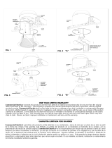
Ceiling
Cable
Hole
Fig. 2
WARNING - RISK OF ELECTRIC SHOCK. DISCONNECT
MAIN POWER AT FUSE OR CIRCUIT BREAKER
BEFORE INSTALLING OR SERVICING THE FIXTURE.
LED 6” RECESSED DOWNLIGHT INSTALLATION
INSTRUCTIONS – Easy-UP™ MODEL CER608943
QUESTIONS? CALL TOLL
FREE 1-877-527-0313
Please read carefully and save these instructions,
as you may need them at a later date.
GENERAL: All electrical connections must be in accordance with local and
National Electrical Code (N.E.C.) standards. Be sure to read these
instructions and review the diagrams thoroughly before beginning. If you are
unfamiliar with proper electrical wiring connections obtain the services of a
qualified electrician.
BEFORE YOU BEGIN
1. Check if the power source is suitable for the added electrical load.
Power should be supplied by a 110/120 volt, 60 Hz single circuit. A
standard 120 volt, 15 amp branch circuit is designed to carry a
maximum load of 1800 watts. We recommend that the total wattage of
all the lights and appliances on that circuit, not exceed 80% or 1440
watts, of the maximum electrical capacity.
2. This fixture is an IC type fixture. It may come in direct contact and
be completely covered with thermal insulation that has an R-value
of 3.85 or less. Some insulation types that meet this requirement
are blanket batting/roll and blown-in loose fill. Do not install in a
ceiling with spray foam type insulation. Any part of the fixture may
come in direct contact with any combustible material, such as a ceiling
joist or floor board.
3. This fixture requires an existing ceiling surface, such as drywall, for
installation. To install this fixture, a hole needs to be made into the
ceiling surface at the desired location. Then, power supply wiring (NM
cable) needs to be installed from the power source to the hole.
4. This fixture is designed for ceiling surfaces that are 3/4” thick or less.
Do not use this fixture on ceiling surfaces that are thicker than ¾”.
5. This fixture may be installed over a wet or damp location such as a
shower stall or bathtub enclosure. The area above the ceiling surface
must, however, be a dry location.
6. To prevent wiring damage or abrasion, do not expose wiring to edges
of sheet metal or other sharp objects.
UNPACK THE FIXTURE
Check the contents of the box. You should have:
• 1 – Fixture
• 1 – Hole Template (6 ¼ ” diameter)
• 3 – Wire Connectors
INSTALLING THE FIXTURE
NOTE: First turn off electricity at the circuit breaker or the fuse box. Turning
the power off by using a wall switch is not sufficient to prevent electrical
shock.
1. Choose the location for the fixture, taking into consideration the 6”
depth clearance requirement, the location of ceiling joists and the
accessibility for the electrical supply. Mark the selected location with a
circle using the provided template.
2. Using a keyhole saw make a 6 ¼ ” hole in the ceiling surface. (Fig. 1)
(Note: Be sure not to make the hole any larger than specified by the
template. An oversized hole may not allow for proper installation.)
3. Run non-metallic (NM) cable (also known as Romex) or an armored
cable (also known as BX) from your circuit breaker or fuse panel to
the hole, providing 6” (15,2 cm) to 8” (20,3 cm) of slack extending
below the hole. Cable having up to 12 AWG wiring may be used. (Fig.
2) (WARNING - Use cables having wires rated 90°C or more.)
4. Open the side door of the junction box. If you are using a BX cable,
remove one of the round knockouts located on the top or sides of the
junction box. If you are using NM cable, remove a rectangular
knockout on the back of the junction box. Insert about 5 or 6 inches of
the NM cable into the junction box through one of the provided strain-
relief slots. (Fig. 3)
5. Remove at least 3” of the cable’s outer sheath and remove the plastic
or paper over-wrap. Strip approximately 3/8” of insulation from the
ends of all supply wires. Using the wire connectors, make the
following wire connections within the junction box (Fig. 3):
WHITE Fixture Wire to WHITE (NEUTRAL) Supply Wire
BLACK Fixture Wire to BLACK (HOT) Supply Wire
Fixture GROUND Wire to Supply GROUND Wire
6. Carefully stuff the wires and the wire connections into the junction box.
Close the junction box top door. Tighten the fastening screw.
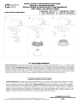
7. Raise the fixture up to the ceiling hole, while simultaneously pushing
the excess NM cable into the hole. (Fig. 4)
8. Flip up and squeeze the spring-loaded wings against the junction box,
as shown, and insert the fixture into the hole, junction box first. (Fig. 4)
Strain-relief
slot
Side Door
Wire
connector
Junction
Box
Fig. 3
ALL RIGHTS RESERVED. COPYRIGHT Commercial Electric 2017
Fig. 1
Ceiling joist
Ceiling

9. Continue inserting the fixture into the hole, while continuing to squeeze
the spring-loaded wings. When the wings reach the hole edge, release
them and push up the fixture until both wings flip down onto the ceiling
surface. (Fig. 5)
Spring-loaded
wing
Ceiling
Fig. 5
Spring-loaded
wing
Junction
Box
Hole
NM or BX cable
Fig. 4
DIMMING
For a complete list of compatible dimmers, please look up the item number
listed on the cover of this instruction manual at www.homedepot.com o
www.homedepot.ca.
SYMPTOM
ACTION
SOLUTION
Lights flicker
during
dimming.
Check if dimmer being
used is compatible
dimmer list from
“DIMMING” section
If dimmer is not on list, replace
it with a dimmer from the list.
Fuse blows or
circuit breaker
trips when
light is turned
on.
Check wire
connections inside the
junction box.
If wiring connections are loose
or disconnected, redo
connections. Make sure there
are no exposed wire
conductors.
If wiring connections are good,
the trim may be defective and
will need to be replaced.
TROUBLESHOOTING
FIVE-YEAR LIMITED WARRANTY
Commercial Electric
warrants this product to be free from defects in
material and workmanship for five years from the original date of purchase
by the consumer. This warranty is limited to the counter replacement at
the time of purchase, with the original purchase receipt. Commercial
Electric
will not be liable for the loss or damage of any kind, incidental or
consequential damages of any kind, whether based on warranty contract
or negligence, and arising in connection with the sale, use or repair of the
product claimed to be defective. Some states do not allow the exclusion
or limitation of incidental or consequential damages so the above limitation
may not apply to you. This warranty gives you specific legal rights and
you may also have other rights, which vary from state to state. Misuse,
accident, improper installation or maintenance will also void the warranty.
___________________________________________________________
This device complies with part 15 of the FCC Rules. Operation is subject
to the following two conditions:
1. This device may not cause harmful interference, and
2. This device must accept any interference received, including
interference that may cause undesired operation.
NOTE: This equipment has been tested and found to comply with the
limits for a Class B digital device, pursuant to Part 15 of the FCC Rules.
These limits are designed to provide reasonable protection against harmful
interference in a residential installation. This equipment generates, uses
and can radiate radio frequency energy and, if not installed and used in
accordance with the instructions, may cause harmful interference to radio
communications. However, there is no guarantee that interference will not
occur in a particular installation. If this equipment does cause harmful
interference to radio or television reception, which can be determined by
turning the equipment off and on, the user is encouraged to try to correct
the interference by one or more of the following measures:
• Reorient or relocate the receiver antenna.
• Increase the separation between the equipment and receiver.
• Install the product onto on a circuit different from that to which the
receiver is connected.
• Consult with the dealer or an experienced radio/TV technician for
help.
CAUTION: Any changes made to the electronics circuit will void this
equipment’s compliance with Part 15 of the FCC Rules and should not be
operated.
ALL RIGHTS RESERVED. COPYRIGHT Commercial Electric 2017
LIGHT DISTRIBUTION MAP.
80
160
240
320
400
-/+180
90
30
60
-30
120
150
-90
-60
-120
-150
0
/