Page is loading ...

Features
Network Display Unit provides annunciation for
up to 12,000 network points:
x The basic NDU is a special purpose master controller
that includes a network interface module
x Combining a basic NDU with a Voice Command Center
(VCC) provides an additional separate Network node
within the same cabinet for control of Network level
Emergency Voice/Alarm Communications Equipment
Master Controller (top) bay:
x Master controller assembly with operator interface
x Enhanced CPU with dual configuration programs,
convenient service port access, and capacity for up to
12,000 points
x System power supply (SPS) and charger (9 A total) with
on-board programmable auxiliary output
x Operator interface that is conveniently color coded with
raised switches providing high confidence feedback
x Construction that is optimized for easy installation,
upgrade, and maintenance
x Glass door (ordered separately) provides view of
available operator controls visible behind locked door
Standard addressable interfaces include:
x Remote annunciator module support via RUI (remote
unit interface) communications port
NDU field installed option modules include:
x DACT and City Connection
x Service modems for remote panel status inquiry
x RS-232 ports for printers or maintenance terminals
x Alarm relays and expansion power supplies
For NDU with VCC:
x Optional features are similar to a networked fire alarm
control panel and an extensive list of modules are
available for; initiating, notification, and user interface
Listed to:
x UL Std. 864, Fire Detection and Control (UOJZ), and
Smoke Control Service (UUKL)
x UL Std. 2017, Process Management Equipment (QVAX)
x UL Std. 1076, Proprietary Alarm Units-Burglar (APOU)
x UL Std. 1730, Smoke Detector Monitor (UULH)
x ULC Std. S527-99
* See pages 4-6 for models that are UL or ULC listed and for additional product listing
details. This product has been approved by the California State Fire Marshal (CSFM)
pursuant to Section 13144.1 of the California Health and Safety Code. See CSFM
Listing 7165-0026:251 (non-high rise) and 7170-0026:250 (high rise) for allowable
values and/or conditions concerning material presented in this document. It is subject to
re-examination, revision, and possible cancellation. Accepted for use – City of New York
Department of Buildings – MEA35-93E. Additional listings may be applicable; contact
your local Simplex product supplier for the latest status. Listings and approvals under
Simplex Time Recorder Co. are the property of Tyco Safety Products Westminster.
On
Off
Auto
On
Off
Auto
On
Off
Auto
On
Off
Auto
On
Off
Auto
On
Off
Auto
On
Off
Auto
On
Off
Auto
Press ACKlocated under flashing indicator.
Repeat operation until all events are acknowledged.
Local tone will silence.
A B C
AC Power
D E F G H I
J K L M N O P Q R
'SP' ( ) , 0 :
S T U V W X Y Z /
ALARMS
Fire Alarm Priority 2 Alarm
SYSTEM WARNINGS
Supervisor y Trouble
Alarm Silenced
Emergency Operating Instructions
Alarm or W arning Cond ition
How to Ack nowled ge / V iew Ev ents
How to Sile nce Bu ildi ng Signa ls
System indicator flashing. Tone On. Press Alarm Silence.
How to Reset System
Press System Reset.
Press Ack to silence tone device.
ZONE
1
SIG
2
AUX
3
FB
4
IO
5
IDNet
6
P
7
A
8
L
9
NET ADDR
0
DEL
Enter C/Exit
Fire Alarm
Ack
Priorit y 2
Ack
Supv
Ack
Trouble
Ack
Alarm
Silence
System
Reset
Event
Time
Enable
On
Arm
Disable
Off
Disarm
Auto
Lamp
Test
More
Info
Menu
Previous
Next
SYSTEM IS N ORMAL
08:23:43 am MON 11-DEC-00
Fire Control
Fire Control
ALARMFIRE
PULL DOWN
ALARMFIRE
PULL DOWN
ALARMFIRE
PULL DOWN
Fire Control
Fire Control
NDU with VCC,
Node 1 and Node 2
Node 3
Node 4
Node 5
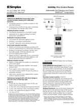
Network One-Line Diagram Showing an NDU with VCC
Introduction
The 4100U Network Display Unit is a network level
annunciator and manual system/point controller. It
provides alphanumeric annunciation for up to 12,000
Network points and/or point lists and can be programmed
to function as the network master controller for Alarm
Silence, Trouble Acknowledge, and System Reset.
Software Revisions. Some of the features detailed and
products listed in this document require 4100U System
Software Revision 11.08 or higher. For pre-11.08 system
expansion options, hardware updates may be required.
Contact your local Simplex
®
product supplier for details.
Fire Control Panels
UL, ULC Listed; FM, CSFM, Network Annunciator Panels
and MEA (NYC) Approved* Network Display Unit (NDU)
S4100-0036-4 10/2003

Introduction (Continued)
Network Overview. When connected to other Network
nodes, individual fire alarm control panels become
components of a distributed intelligence system. Each
panel that directly connects to the network is called a
network “node” and is capable of performing individual
supervision and control on its locally connected devices
but has the ability to inform the 4100U NDU (as well as
other network control panels) of point status and panel
condition. This allows system information to reach the
proper location for appropriate system response.
Multiple 4100U NDUs (separately packaged) can be
connected to a Network to duplicate common information
at separate locations, or direct selected information by
type such as troubles, alarms, control, etc.
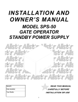
NDU Module Bay Description
The NDU Master Controller Bay (top) includes a
special purpose system power supply with battery charger
(SPS), the master controller board, a Network Interface
Module, and operator interface equipment similar to that
used on the standard fire alarm control modules. Slots 1
and 2 are available for single slot panel mounted modules.
The NDU with VCC includes an expansion bay with
separate: master controller board, Network Interface
Module, and a standard SPS. This results in two separate
Network nodes residing within the same cabinet.
In this bay (typically the second expansion bay), Slots 1
and 2 are available for single slot panel mounted modules
and optional LED/switch modules can also be mounted.
The Battery Compartment (bottom) accepts two
batteries, up to 50 Ah, to be mounted within the cabinet
without interfering with module space.
Refer to the NDU with VCC internal module bay
reference illustration for typical three bay cabinet module
location.
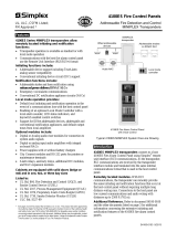
Operator Interface Detail Reference
The following illustration identifies the primary functions
of the operator interface.
Press ACK located under flashing indica tor.
Repeat operation unt il all events are acknowledged.
Local tone will si lence.
A B C
AC Power
D E F G H I
J K L M N O P Q R
'SP' ( ) , 0 :
S T U V W X Y Z /
ALARMS
Fire Alarm Pri ority 2 Alarm
SYSTEM WARNINGS
Supervisory Trouble
Alarm Sile nced
Emergency Operating Instructions
Alarm or Warning Condition
How to Acknowledge / View Events
How to Silence Building Signals
System i ndicator flashing. T one On. Press Alarm Silen ce.
How to Reset System
Press System Reset.
Press Ack to silence tone devic e.
ZONE
1
SIG
2
AUX
3
FB
4
IO
5
IDNet
6
P
7
A
8
L
9
NET ADDR
0
DEL
Enter C/Exit
Fire Alarm
Ack
Priority 2
Ack
Supv
Ack
Trouble
Ack
Alarm
Silence
System
Reset
Event
Time
Enable
On
Arm
Disable
Off
Disarm
Auto
Lamp
Test
More
Info
Menu
Previous
Next
SYSTEM IS NORMAL
08:23:43 am MON 11-DEC-00
Upload/Download
port access (under
sliding cover)
Basic operator instructions
are printed on the interface
mounting plate
Panel sounder
Operator interface panel is directly
viewable and accessible (no access door)
SYSTEM IS NORMAL
08:23:43 am WED 01-OCT-03
PDI
4x5 Module
Expansion Power
Supply
(XPS)
4x5 Module
I/O Wiring
I/O Wiring
I/O Wiring
4100 Option
4100 Option
4100 Option
Slot 1 Slot 2 Slot 3 Slot 4 Slot 5 Slot 6 Slot 7 Slot 8
(Block E)
(Block F)
(Blocks G & H)
System Power
Supply
(SPS)
IDNet
NACs 1, 2 & 3
Aux Pwr
Aux
Relay
Btry
+
-
Master Controller
Board
Slot 1 Slot 2 Slot 3 Slot 4 Slot 5 Slot 6 Slot 7 Slot 8
Slot 1
Slot 2
Slot 4
Slot 3
System Power
Supply
(SPS)
IDNet
NACs 1, 2 & 3
Aux Pwr
Aux
Relay
Btry
+
-
Master Controller
Board
Slot 1 Slot 2 Slot 3 Slot 4 Slot 5 Slot 6 Slot 7 Slot 8
Slot 1
Slot 2
Slot 4
Slot 3
NDU Master
Controller Bay
Battery Compartment
System power supply
Expansion bay with
mixed module sizes
Expansion Bay 1
Master Controller Board:
Slot 3 is Network Interface
Slot 4 is Master Controller
NDU with VCC
Expansion Bay 2
Master Controller Board:
Slot 3 is Network Interface
Slot 4 is Master Controller
NDU with VCC Internal Module Bay Reference
Packaging Availability
x Modules are power-limited (unless specifically noted
otherwise)
x Enclosure are available for either two or three bay
sizes or for cabinet rack mounting
x Additional cabinets can be mounted close-nippled for
module expansion
x Boxes, doors with tempered glass inserts, and dress
panels are available in beige or red (ordered
separately)
x Refer to document S4100-0037 for enclosure details
Software Feature Summary
x Selectable service override allows authorized operators
to clear alarm conditions during System Reset even if
status has gone to trouble before reset occurred
x Duplicate address error detection
x Convenient PC programming using a Microsoft
®
Windows
®
user interface based program
x WALKTEST™ silent or audible system test
(protected under U.S. patent No. 4,725,818)
2 S4100-0036-4 10/2003

Operator Interface
Convenient Status Information. With the locking
door closed, the glass window allows viewing of the
display, status LEDs, and available operator switches.
Features include a two-line by 40-character, wide viewing
angle (super-twist) LCD with status LEDs and switches as
shown in the illustration below.
LED indicators describe the general category of activity
being displayed with the LCD providing more detail. For
the authorized user, unlocking the door provides access to
the control switches and allows further inquiry by
scrolling the display for additional detail.
Operator Interface Features
x Convenient and extensive operator information is
provided using a logical, menu-driven display
x Multiple automatic and manual diagnostics for
maintenance reduction
x History Logs are available from the LCD or capable of
being printed
x Convenient PC programmer label editing
x Password access control
A B C
AC Power
D E F G H I
J K L M N O P Q R
'SP' ( ) , 0 :
S T U V W X Y Z /
ALARMS
Fire Alarm Priority 2 Alarm
SYSTEM WARNINGS
Supervisory Trouble
Alarm Silenced
ZONE
1
SIG
2
AUX
3
FB
4
IO
5
IDNet
6
P
7
A
8
L
9
NET ADDR
0
DEL
Enter C/Exit
Fire Alarm
Ack
Priority 2
Ack
Supv
Ack
Trouble
Ack
Alarm
Silence
System
Reset
Event
Time
Enable
On
Arm
Disable
Off
Disarm
Auto
Lamp
Test
More
Info
Menu
Previous
Next
SYSTEM IS NORMAL
08:23:43 am WED 01-OCT-03
SIX SYSTEM STATUS INDICATOR LEDs
provide system status indications in addition
to LCD information, LEDs flash to indicate
the condition and then when acknowledged,
remain on until reset :
Fire Alarm & Priority 2 Alarm, red LED
Supervisory & Trouble, yellow LED
Alarm Silenced, yellow LED
AC Power, green LED (on for normal)
FIVE PROGRAMMABLE
FUNCTION SWITCHES,
each with a yellow LED
indicator
POINT STATUS
CONTROL KEYS:
Point Enable and
Disable
Force On or Arm
Force Off or Disarm
Return On/Off or
Arm/Disarm to Auto
Mode
NUMERIC KEYPAD for
point category and point
selection (alphabet
characters are not used at
this time)
ADDITIONAL
FUNCTION KEYS:
Event Time Request
More Information Request
Lamp Test
Elevator Recall
City Disconnect
Manual Evac
Ground Fault
Waterflow-West
Waterflow-East
Custom label insert
LCD NAVIGATION
CONTROL:
Menu selection
Vertical and
Horizontal position
selection buttons
FIRE ALARM ACK acknowledges a Fire Alarm
condition, logs the acknowledge, and silences the
operator panel and all annunciator tone-alerts
PRIORITY 2 ACK acknowledges a Priority 2 Alarm
condition, logs the acknowledge, and silences the
operator panel and all annunciator tone-alerts
SUPV ACK acknowledges system supervisory
conditions, logs the acknowledge, and silences the
operator panel and all annunciator tone-alerts
TROUBLE ACK acknowledges system troubles, logs
the acknowledge, and silences the operator panel and
all annunciator tone-alerts
ALARM SILENCE causes audible notification
appliances to be silenced (depending on panel
programming) typically after evacuation is complete and
while alarm source is being investigated; may allow
visible notification to continue (strobes still flashing)
SYSTEM RESET restores control panel to normal when
all alarmed inputs are returned to normal
2 X 40 LCD READOUT, LED backlighted
during normal conditions and abnormal
operating conditions, provides up to 40
characters for custom label information
FIRST ALARM DISPLAY: Operation can
be selected for maintained display of first
alarm until acknowledged
THREE PROGRAMMABLE LEDs
provide custom labeling, the top
two LEDs are selectable as red or
yellow, the bottom LED is
selectable as green or yellow
ULC SYSTEMS
require designating
a Ground Fault
indicator
3 S4100-0036-4 10/2003

Standard Module Details
Master Controller & Motherboard:
x The master controller mounts in Slot 4 of a two slot
motherboard (Slots 3 and 4 of the Master Controller Bay)
and provides a standard RUI communications channel,
selectable as Style 4 or Style 7, available at Slot 4
x RUI communications control up to 31 remote
annunciators per channel including the 4603-9101 LCD
Annunciator, the 4602-9101 Status Command Unit
(SCU), and 4602-9102 Remote Command Unit (RCU)
x Up to four RUI channels are allowed (use 4100-1291 as
required)
x A Network Interface Module is mounted in Slot 3
x Optional Service Modem 4100-6030 mounts onto the
master controller board with its own on-board
connections
System Power Supply:
x Rating is 9 A total, including module currents
x Outputs are power-limited, except for the battery charger
System Power Supply (Continued):
x Provides system power, battery charging, auxiliary power,
earth detection, and provisions for either an optional City
Connect Module or an optional Alarm Relay Module
x Dual rate, temperature compensated battery charger
charges up to 50 Ah sealed lead-acid batteries mounted
in the battery compartment; charger is UL listed for
charging up to 110 Ah batteries mounted in an external
cabinet (refer to data sheet S2081-0012 for details)
x Performs battery monitor including low battery warning
x Provides status information to the master controller and
analog values for battery voltage, charger voltage and
current, and actual system voltage and current
x
2 A Auxiliary Power Output is selectable for detector
reset, door holder, or coded output operation
x
Optional City Connect Module (4100-6031, with
disconnect switches, or 4100-6032, without disconnect
switches) can be selected for conventional dual circuit
city connections
x
Optional Alarm Relay Module (4100-6033) provides
three Form C relays that are used for Alarm, Trouble,
and Supervisory, rated 2 A resistive @ 32 VDC
4 S4100-0036-4 10/2003
Battery Current
Model Description
Module
Size
Supv. Alarm
4100-6056 Wired Network Media Card N.A. 55 mA 55 mA
4100-6057 Fiber Optic Media Card
Select per Network connection requirements, two media
cards are required per network interface; mounts on the
supplied Network Interface Module(s)
N.A. 25 mA 25 mA
4100-6055
Network Access Dial-in Service Modem, mounts to supplied Network Interface Module,
requires telephone line connection
N.A. 75 mA 75 mA
4100-1291 Remote Unit Interface Module (RUI); up to three maximum per control panel 1 Slot 85 mA 85 mA
4100-6030
Service Port Modem for local panel access only, mounts to Master Controller Module,
requires telephone line connection, accesses same information as front panel port
N.A. 70 mA 70 mA
4100-6031 City Circuit, with disconnect switches N.A. 20 mA 36 mA
4100-6032 City Circuit, without disconnect switches
For use with SPS
only, not RPS
N.A. 20 mA 36 mA
4100-6033 Alarm Relay, 3 Form C relays, 2 A @ 32 VDC (one per RPS)
Select one per
SPS (mounts on
SPS/RPS)
N.A. 15 mA 37 mA
4100-6038 Dual RS-232 Interface; 3 maximum; can mount in Slot 3 or Slot 2 of Master Controller 1 Slot 132 mA 132 mA
4100-6052 DACT, Point or Event Reporting; includes 2, 14 ft (4.3 m) DACT cables 1 Slot 30 mA 40 mA
4100-6036 Physical Bridge, Style 4, includes 1 modem module and 2 wired modules 1 Slot 260 mA 260 mA
4100-6037 Physical Bridge, Style 7, includes 2 modem and 2 wired modules 2 Slots 304 mA 304 mA
4100-0156 8 VDC Converter, required for multiple Physical Bridge Modules; 3 A @ 8 VDC maximum 1 Block 1.5 A maximum
4100-9816 Master Clock Interface Module with one standard RS-232 port (see S4100-0033) 1 Slot 132 mA 132 mA
4100-1290 24 Point I/O Module for external connections, select each point as either input or output 1 Slot (see S4100-0032)
Network Display Unit, Non-Voice
Battery Current
Model Model Type/Listing Description
Supv. Alarm
4100-9141 120 VAC Input UL 419 mA 476 mA
4100-9143 Canadian, English ULC
4100-9144 Canadian, French ULC
4100-9241 220-240 VAC Input UL
4100U NDU with Master Controller, LCD and operator interface,
Network Interface Module (select media card separately), 9 A system
power supply/battery charger, and external RUI communications interface
(power supply/battery charger is an SPS with its IDNet™ channel and
NACs disabled)
see below for
selected Network
Media Card current
Network Display Unit with Voice Command Center (VCC)
Battery Current
Model Model Type/Listing Description
Supv. Alarm
4100-9142 120 VAC Input UL 828 mA 947 mA
4100-9145 Canadian, English ULC
4100-9146 Canadian, French ULC
4100-9242 220-240 VAC Input UL
4100U NDU with VCC includes the first bay equipment described for the
NDU (above) and a second bay assembly with separate: Master
Controller for voice functions, Network Interface (select media card
separately), and a standard SPS with 250 point IDNet channel; and 3, 3 A
Class A/B NACs capable of SmartSync™ two-wire operation
see below for
selected Network
Media Card current
NDU Equipment Selection
NDU, or NDU with VCC Communication Modules

5 S4100-0036-4 10/2003
Model Description Details and Mounting Reference
4100-1243
Master Microphone Module; one maximum
per audio system; mounts on front panel
Requires 2 Slots (4” [102 mm]), locate on expansion bay only; space behind
for 4100U flat modules only Supv. current = 2.4 mA; Active current = 6 mA
4100-1252 1 Channel (audio or mike)
4100-1253 1.5 Channel (audio + mike)
4100-1254 2 Channel (full audio)
4100-1255 3-8 Channel
Operator
Interface
Modules
Single slot modules requiring connection to an LED/switch controller (see
page 9); space behind controller accepts 4100U flat modules only
Additional adjacent LED/switch module(s) are required for specific speaker
circuit selection
Firefighter Telephone System Products (refer to S4100-0034 for additional detail)
Model Description Details and Mounting Reference
4100-1270
Master Telephone with Telephone Control
Module and 3 Class B telephone NACs; for
Fire Alarm Control Panels
One max. per audio system; front panel module; space behind for 4100U flat
modules only; telephone control module mounts on bay module mounting
plate; use LED/switch modules for circuit control
4100-1272 Telephone Module with 3 phone NACs Class B NACs, single Block module, mounts to bay mounting plate
4100-1273 Telephone Class A Adapter Module Mounts to 4100-1272, no additional space required
Analog Emergency Voice/Alarm Communications Equipment, Constant Supervision Compatible*
Model Description Details
4100-9620
Basic Analog Audio Operation with microphone, requires
dedicated expansion bay
Includes: Expansion Bay, 4100-1210 Analog Controller Board,
Microphone Module, and Audio Expansion Bay Kit
4100-1210
Analog Controller Board only; order expansion bay and
audio expansion bay kit separately
Controller board mounts in Blocks A and B
4100-1361 25 VRMS output NAC rating = 1.4 A
4100-1362 70.07 VRMS output
Flex-35, 35 W Amplifier,
constant supervision compatible
NAC rating = 0.5 A
35 W, or 100
speakers
4100-1312 25 VRMS output NAC rating = 2 A
4100-1313 70.7 VRMS output
Flex-50, 50 W Amplifier,
constant supervision compatible
Includes three on-board
Class B audio NACs;
power is supplied from an
XPS, RPS, or SPS
NAC rating = 0.707 A
50 W, or 100
speakers
100 W Analog Amplifiers with Power Supply, Constant Supervision Compatible
Model/Output Voltage
25 VRMS 70.7 VRMS
Power Supply Input/Listing Description Details
4100-1314 4100-1315 120 VAC, 60 Hz UL
4100-1316
4100-1317
120 VAC, 60 Hz ULC
4100-1318
4100-1319
220/230/240 VAC, 50/60 Hz UL
Primary
100 W
Amplifier
Includes six, Class B audio NACs;
NAC rating = 50 W or 100 speakers
maximum; 2 A @ 25 VRMS;
1.4 A @ 70.7 VRMS
4100-1320
4100-1321
120 VAC, 60 Hz UL
4100-1322
4100-1323
120 VAC, 60 Hz ULC
4100-1324
4100-1325
220/230/240 VAC, 50/60 Hz UL
Backup
100 W
Amplifier
Uses the six Class B NACs of primary
amplifier
ULC
models
have low
battery
dropout
circuit
Digital Emergency Voice/Alarm Communications Equipment*
Model Description Details
4100-9621
Basic Digital Audio Operation with microphone, requires
dedicated expansion bay
Includes: Expansion Bay, 4100-1311 Digital Controller Board,
Microphone Module, and Audio Expansion Bay Kit
4100-1311
Eight Channel Digital Controller Board only; order
expansion bay and audio expansion bay kit separately
Controller board mounts in Blocks A and B
4100-1363 25 VRMS output NAC rating = 1.4 A
4100-1364 70.07 VRMS output
Flex-35, 35 W Amplifier,
constant supervision compatible
NAC rating = 0.5 A
35 W, or 100
speakers
4100-1326 25 VRMS output NAC rating = 2 A
4100-1327 70.7 VRMS output
Flex-50, 50 W Amplifier,
constant supervision compatible
Includes three on-board
Class B audio NACs;
power is supplied from an
XPS, RPS, or SPS
NAC rating = 0.707 A
50 W, or 100
speakers
100 W Digital Amplifiers with Power Supply, Constant Supervision Compatible
Model/Output Voltage
25 VRMS 70.7 VRMS
Power Supply Input/Listing Description Details
4100-1328 4100-1329 120 VAC, 60 Hz UL
4100-1330 4100-1331 120 VAC, 60 Hz ULC
4100-1332 4100-1333 220/230/240 VAC, 50/60 Hz UL
Primary
100 W
Amplifier
Includes six, Class B audio NACs;
NAC rating = 50 W or 100 speakers
maximum; 2 A @ 25 VRMS;
1.4 A @ 70.7 VRMS
4100-1334 4100-1335 120 VAC, 60 Hz UL
4100-1336 4100-1337 120 VAC, 60 Hz ULC
4100-1338 4100-1339 220/230/240 VAC, 50/60 Hz UL
Backup
100 W
Amplifier
Uses the six Class B NACs of primary
amplifier
ULC
models
have low
battery
dropout
circuit
Options for use with either Analog or Digital Amplifiers*
Model Description Model Description
4100-1245
Flex-35/50 NAC Expansion Module; (Adds 3
Class B, 1.5 A NACs)
4100-1248
100 W Amplifier NAC Expansion Module; (Adds six
Class B, 2 A NACs)
4100-1246
Flex-35/50 Class A Adapter for 3 NACs
4100-1249
100 W Amplifier Class A Adapter Module for 6 NACs
* Refer to document S4100-0034 for additional audio module information. Continued on next page
NDU with VCC, Emergency Voice/Alarm Communications Selection*

6 S4100-0036-4 10/2003
LED/Switch Modules, General Purpose (LED/switch controller and label kit is ordered separately)
Model LEDs per Switch LED Color(s) LED Quantity Switch Quantity
4100-1276 Red; pluggable 8
4100-1277
LEDs only
Red on top, Yellow on bottom, pluggable 16
LEDs only
4100-1280 One Red
4100-1281 One Yellow
8
4100-1282 Two Red on top, Yellow on bottom
4100-1283 Two Yellow, top and bottom
4100-1284 Two Red on top, Green on bottom
4100-1296 Two Green on top, Yellow on bottom
16
8
4100-1285 One Red
4100-1278 One 8 Red on left, 8 Yellow on right
16 16
4100-1287 One Red 24 24
LED/Switch Modules, Special Purpose (LED/switch controller and label kit is ordered separately)
Model Operation
4100-1286 Eight function HOA (On, Off, Auto) Control Module with labeled switches; ON/OFF/Auto; Green/Red/Green LEDs
4100-1295 Eight function HOA (On, Off, Auto) Control Module, same as 4100-1286 except switches are unlabeled
LED/Switch Controller Modules and Accessories (LED kits for 4100-1276/1277 are on page 7)
Model Description
4100-1288
64 LED/64 Switch Controller Module with mounting plate; controls up to 64 LEDs and
interfaces to up to 64 switches; mounts behind the LED/switch modules and has
provisions for one 4100-1289 Controller Module
4100-1289
64 LED/64 Switch Controller Module without mounting plate; mounts on extra space of
4100-1288; controls an additional 64 LEDs and 64 switches
NOTE: LED/switch controllers and
their connected LED/switch
modules must be in the same bay.
4100-1294 LED/Switch Module Slide-in Labels, required when LED/switch modules are present; order one per cabinet
Model Color Model Color Model Color Description
4100-9843 Yellow 4100-9844 Green 4100-9845 Red Kits of 8 LEDs; order as required for 4100-1276/1277 modules
Model Voltage/Listing Description Size Supv. Alarm
4100-5101 120 VAC UL
4100-5103 120 VAC, Canadian ULC
4100-5102 220-240 VAC UL
Expansion Power Supply (XPS); 9 A output, 3 built-in 3 A
Class A/B NACs that can provide synchronized strobe or
SmartSync™, two-wire operation
2
Blocks
50 mA 50 mA
4100-5115 NAC Expansion Module, 3 NACs, Class A/B, mounts on XPS only N.A. 25 mA 25 mA
4100-5111 120 VAC UL
4100-5112 120 VAC, Canadian ULC
4100-5113 220-240 VAC UL
Additional System Power Supply (SPS); 9 A power
supply/charger with 250 point IDNet channel, 3 Class A/B
NACs, and expansion slot for City Circuit or Alarm Relay
option; Canadian model has low battery cutout
4
Blocks
175 mA 225 mA
4100-5125 120 VAC UL
4100-5126 120 VAC, Canadian ULC
4100-5127 220/230/240 VAC UL
Remote Power Supply (RPS); 9 A power supply with battery
charger for up to 50 Ah batteries; 3 built-in Class A/B NACs,
same as in XPS
4
Blocks
150 mA 185 mA
4100-5120 120 VAC UL
4100-5121 120 VAC, Canadian ULC
4100-5122 220-240 VAC UL
TrueAlert
®
Power Supply (TPS); 3 Class B SLCs rated 3 A
each for up to 63 TrueAlert addressable appliances per
channel, 189 per TPS; built-in battery charger; 2 A aux. power
output; add device current separately, 0.2 mA standby (see
S4009-0003 for additional detail)
4
Blocks
88 mA 100 mA
4100-5124 TrueAlert SLC Class A Adapter for all 3 SLCs, mounts on TPS only N.A. 7 mA 7 mA
4100-5152 12 VDC Power Option, 2 A @ 12 VDC maximum 1 Block 1.5 A maximum
4100-0634 120 VAC
4100-0635 220/230/240 VAC
Power Distribution Module (PDM); select per system voltage;
one required per box or cabinet rack
Options for either Analog or Digital Systems (refer to data sheet S4100-0034 for additional module details)
Model Description Model Description
4100-1259 Constant Supervision Adapter for 25 VRMS Amplifiers 4100-5116 Expansion Signal Module; three, 1.5 A NACs
4100-1260 Constant Supervision Adapter for 70.7 VRMS Amplifiers 4100-1266 NAC Extender
4100-1240 Auxiliary Audio Input Module; four additional inputs 4100-1267 Class A Adapter
4100-1241 8 Minute Message Expansion Module 4100-1268 Constant Supervision Adapter
Options for use with
Expansion Signal
Module
4100-1242 32 Minute Message Expansion Module 4081-9018 End-of-line resistor for 70.7 VRMS NACs; 10 k:, 1 W
NDU with VCC, Emergency Voice/Alarm Communications Selection (Continued)
NDU with VCC, LED/Switch Modules (refer to S4100-0032 for additional detail)
Expansion, Remote, and TrueAlert Power Supplies and Accessories for NDU with VCC

120 VAC Models 3.5 A maximum @ 102 to 132 VAC, 60 Hz
Input Power [System (SPS); Expansion (XPS);
Remote (RPS); TrueAlert (TPS) and 100 W
amplifiers]
220-240 VAC Models
1.75 A maximum @ 204 to 264 VAC, 50/60 Hz;
separate taps for 220/230/240 VAC
Total Power Supply
Output Rating
9 A total @ nominal 28 VDC, including module currents and
auxiliary power outputs
Auxiliary Power Tap 2 A maximum @ nominal 28 VDC
Power Supply Output
Ratings (System,
Expansion, and Remote
Power Supplies)
NACs Programmed
for Auxiliary Power
2 A maximum per NAC, 5 A maximum @ nominal 28 VDC
Output switches to
battery backup
during mains AC
failure or brownout
conditions
Battery capacity range
6.2 Ah to 50 Ah; selectable via programming for batteries below 18 Ah; the SPS is UL
listed for up to 110 Ah battery charging for remotely located batteries
Battery Charger
(System and Remote
Power Supply)
Charger characteristics
and performance
Temperature compensated, dual rate, recharges depleted batteries within 48 hours per
UL Standard 864, to 70% capacity in 12 hours per ULC Standard S527
Operating Temp. Range 32° to 120°F (0° to 49° C)
Environmental
Operating Humidity Range Up to 93% RH, non-condensing @ 90° F (32° C) maximum
Model Description
4100-6034 Door Tamper Switch with built-in addressable IDNet IAM, one per cabinet assembly if required
4100-2320 Audio Bay-to-Bay Interconnection Harness Kit; order one for each audio bay addition
4100-0637 Audio Box Interconnection Harness Kit; order one for each close-nippled audio cabinet
4100-9835 Termination and Address Label Kit (for module marking); provides additional labels for field installed modules
4100-1293 Panel Mount Thermal Printhead Printer, supplied with one roll of paper; requires 3 Slots; see S4100-0032 for details
4190-9803 Replacement Paper for 4100-1293 Printer, one roll
4100-6045 Coded Manual Station Decoder Module; 3 Slot module; 85 mA supervisory, 163 mA alarm; see S4100-0018 for details
4100-6048 VESDA
®
Air Aspiration Interface; 1 Slot module; 132 mA supervisory or alarm, see S4100-0026 for details
Model* Description Model* Description Model* Description
4100-5005 8 Zone IDC, Class B 4100-3101 250 Point IDNet Module 4100-3202 4 DPDT Relays w/feedback, 10 A
4100-5015 8 Zone IDC, Class A 4100-3102 127 Point MAPNET II
®
Module 4100-3204 4 DPDT Relays w/feedback, 2 A
* See S4100-0031 for details 4100-3103 IDNet/MAPNET II Quad Isolator 4100-3206 8 SPDT Relays, 3 A
Model Description
4100-1279 Single blank 2” display cover; order as required (8 fill a bay front); two max. in a row between LED/switch modules
4100-2210 Appliqué, Canadian French, 4100U Fire Control
4100-2300 Expansion Bay Hardware, order for each expansion bay (unless included with selected option)
4100-0636 Box Interconnection Harness Kit; order one for each close-nippled cabinet
4100-0632 Terminal Block Module; 2, 16 position terminal blocks mounted on 4” x 5” single block size, for up to 12 AWG wire (3.31 mm
2
)
7 S4100-0036-4 10/2003
Slot 1 Slot 8Slot 7Slot 6Slot 5Slot 4Slot 3Slot 2
Expansion Bay Chassis
Block A
Block B
Block C
Block D
Block E
Block F
Block G
Block H
Size Definitions: Block = 4” W x 5” H (102 mm x 127 mm) card area
Slot = 2” W x 8” H (51 mm x 203 mm) motherboard with daughter card
General Specifications
Expansion Bay Module Loading Reference (exact locations are provided with shipped product)
Description Mounting
Terminal Block Module 4” x 5”, 1 block
Style 4 Physical Bridge 2”, 1 slot
Style 7 Physical Bridge 4”, 2 slots
System, Remote, or TrueAlert
Power Supply
Blocks E, F, G & H
ONLY
Expansion Power Supply Blocks G & H ONLY
Audio Controller Modules Blocks A & B
Flex-35 Amplifiers, 2 max/bay*
Blocks E & F; C & D; or
A & B
Flex-50 Amplifiers, 2 max/bay* Blocks E & F or C & D
100 W Amplifiers, 1 max/bay Blocks E, F, G & H
100 W Backup Amplifiers, 1 max.
per bay with primary amplifier
Blocks A, B, C & D
Master Telephone Module Blocks A & B
Master Microphone Module (do
not mount next to telephone)
Two vertical Blocks,
any location
Telephone Module 1 Block
Operator LED/Switch Modules 1 Slot
* NOTE: When mounting dual Flex amplifiers on an
expansion bay, special mounting rules apply.
NDU with VCC, Additional Options
NDU or NDU with VCC Additional Options

Tyco, Simplex, the Simplex logo, MINIPLEX, IDNet, SmartSync, MAPNET II, TrueAlert and WALKTEST are trademarks of Tyco International Services AG or its affiliates in the
U.S. and/or other countries. Microsoft and Windows are registered trademarks of Microsoft Corporation. VESDA is a trademark of Vision Products Pty Ltd.
Door thickness
1-3/8"(35 mm)
Exposed cabinet for
semi-flush mounting
1-3/8" (35 mm)
minimum
Exposed door and
cabinet for semi-
flush mounting
2-3/4" (70 mm)
minimum
24" (610 mm)
8-3/8"
(213 mm)
6-29/32"
(175 mm)
4" stud
6" stud
Knockout screw/nail holes
(for semi-flush mounting)
Stud alignment
markers, each side
Wall board reference
for semi-flush
mounting, 6" stud
Optional semi-flush
trim kit reference
Front view, box outline without door Side view with door attached
2 Bay height 40" (1016 mm)
Doors can be hinged left or right
3 Bay height 56" (1422 mm)
Subject Data Sheet Subject Data Sheet
Basic Panel Modules and Accessories S4100-0031 MINIPLEX
®
Transponders S4100-0035
LED/Switch Modules S4100-0032 Enclosures S4100-0037
Master Clock Interface Module S4100-0033 Remote Annunciators S4100-0038
4100U Audio/Phone Modules S4100-0034 Remote Battery Charger S4081-0002
Tyco Safety Products Westminster • Westminster, MA • 01441-0001 • USA S4100-0036-4 10/2003
www.tycosafetyproducts-usa-wm.com
© 2003 Tyco Safety Products Westminster. All rights reserved. All specifications and other information shown were current as of document revision date and are subject to change without notice.
Wall Mounted Enclosure Installation Reference
NOTE: A system ground must be provided for Earth Detection and transient protection devices. This connection
shall be made to an approved, dedicated Earth connection per NFPA 70, Article 250, and NFPA 780.
Additional 4100U Data Sheet Reference
/