Page is loading ...

R
IP 21S
NTRL/C
UNDER-COOLER CART
OPERATOR’S MANUAL
IM723-A
January, 2004
Safety Depends on You
Lincoln arc welding and cutting
equipment is designed and built
with safety in mind. However, your
overall safety can be increased by
proper installation ... and thought-
ful operation on your part. DO
NOT INSTALL, OPERATE OR
REPAIR THIS EQUIPMENT
WITHOUT READING THIS
MANUAL AND THE SAFETY
PRECAUTIONS CONTAINED
THROUGHOUT. And, most
importantly, think before you act
and be careful.
For use with machines having Code Numbers:
10808, 11068
• Sales and Service through Subsidiaries and Distributors Worldwide •
Cleveland, Ohio 44117-1199 U.S.A. TEL: 216.481.8100 FAX: 216.486.1751 WEB SITE: www.lincolnelectric.com
• World's Leader in Welding and Cutting Products •
Copyright © 2004 Lincoln Global Inc.
RETURN TO MAIN MENU

FOR ENGINE
powered equipment.
1.a. Turn the engine off before troubleshooting and maintenance
work unless the maintenance work requires it to be running.
____________________________________________________
1.b. Operate engines in open, well-ventilated
areas or vent the engine exhaust fumes
outdoors.
____________________________________________________
1.c. Do not add the fuel near an open flame
welding arc or when the engine is running.
Stop the engine and allow it to cool before
refueling to prevent spilled fuel from vaporiz-
ing on contact with hot engine parts and
igniting. Do not spill fuel when filling tank. If
fuel is spilled, wipe it up and do not start
engine until fumes have been eliminated.
____________________________________________________
1.d. Keep all equipment safety guards, covers and devices in
position and in good repair.Keep hands, hair, clothing and
tools away from V-belts, gears, fans and all other moving
parts when starting, operating or repairing equipment.
____________________________________________________
1.e. In some cases it may be necessary to remove safety
guards to perform required maintenance. Remove
guards only when necessary and replace them when the
maintenance requiring their removal is complete.
Always use the greatest care when working near moving
parts.
___________________________________________________
1.f. Do not put your hands near the engine fan.
Do not attempt to override the governor or
idler by pushing on the throttle control rods
while the engine is running.
___________________________________________________
1.g. To prevent accidentally starting gasoline engines while
turning the engine or welding generator during maintenance
work, disconnect the spark plug wires, distributor cap or
magneto wire as appropriate.
i
SAFETY
i
ARC WELDING CAN BE HAZARDOUS. PROTECT YOURSELF AND OTHERS FROM POSSIBLE SERIOUS INJURY OR DEATH.
KEEP CHILDREN AWAY. PACEMAKER WEARERS SHOULD CONSULT WITH THEIR DOCTOR BEFORE OPERATING.
Read and understand the following safety highlights. For additional safety information, it is strongly recommended that you
purchase a copy of “Safety in Welding & Cutting - ANSI Standard Z49.1” from the American Welding Society, P.O. Box
351040, Miami, Florida 33135 or CSA Standard W117.2-1974. A Free copy of “Arc Welding Safety” booklet E205 is available
from the Lincoln Electric Company, 22801 St. Clair Avenue, Cleveland, Ohio 44117-1199.
BE SURE THAT ALL INSTALLATION, OPERATION, MAINTENANCE AND REPAIR PROCEDURES ARE
PERFORMED ONLY BY QUALIFIED INDIVIDUALS.
WARNING
Mar ‘95
ELECTRIC AND
MAGNETIC FIELDS
may be dangerous
2.a. Electric current flowing through any conductor causes
localized Electric and Magnetic Fields (EMF). Welding
current creates EMF fields around welding cables and
welding machines
2.b. EMF fields may interfere with some pacemakers, and
welders having a pacemaker should consult their physician
before welding.
2.c. Exposure to EMF fields in welding may have other health
effects which are now not known.
2.d. All welders should use the following procedures in order to
minimize exposure to EMF fields from the welding circuit:
2.d.1.
Route the electrode and work cables together - Secure
them with tape when possible.
2.d.2. Never coil the electrode lead around your body.
2.d.3. Do not place your body between the electrode and
work cables. If the electrode cable is on your right
side, the work cable should also be on your right side.
2.d.4. Connect the work cable to the workpiece as close as
possible to the area being welded.
2.d.5. Do not work next to welding power source.
1.h. To avoid scalding, do not remove the
radiator pressure cap when the engine is
hot.
CALIFORNIA PROPOSITION 65 WARNINGS
Diesel engine exhaust and some of its constituents
are known to the State of California to cause can-
cer, birth defects, and other reproductive harm.
The engine exhaust from this product contains
chemicals known to the State of California to cause
cancer, birth defects, or other reproductive harm.
The Above For Diesel Engines
The Above For Gasoline Engines

ii
SAFETY
ii
ARC RAYS can burn.
4.a. Use a shield with the proper filter and cover
plates to protect your eyes from sparks and
the rays of the arc when welding or observing
open arc welding. Headshield and filter lens
should conform to ANSI Z87. I standards.
4.b. Use suitable clothing made from durable flame-resistant
material to protect your skin and that of your helpers from
the arc rays.
4.c. Protect other nearby personnel with suitable, non-flammable
screening and/or warn them not to watch the arc nor expose
themselves to the arc rays or to hot spatter or metal.
ELECTRIC SHOCK can
kill.
3.a. The electrode and work (or ground) circuits
are electrically “hot” when the welder is on.
Do not touch these “hot” parts with your bare
skin or wet clothing. Wear dry, hole-free
gloves to insulate hands.
3.b. Insulate yourself from work and ground using dry insulation.
Make certain the insulation is large enough to cover your full
area of physical contact with work and ground.
In addition to the normal safety precautions, if welding
must be performed under electrically hazardous
conditions (in damp locations or while wearing wet
clothing; on metal structures such as floors, gratings or
scaffolds; when in cramped positions such as sitting,
kneeling or lying, if there is a high risk of unavoidable or
accidental contact with the workpiece or ground) use
the following equipment:
• Semiautomatic DC Constant Voltage (Wire) Welder.
• DC Manual (Stick) Welder.
• AC Welder with Reduced Voltage Control.
3.c. In semiautomatic or automatic wire welding, the electrode,
electrode reel, welding head, nozzle or semiautomatic
welding gun are also electrically “hot”.
3.d. Always be sure the work cable makes a good electrical
connection with the metal being welded. The connection
should be as close as possible to the area being welded.
3.e. Ground the work or metal to be welded to a good electrical
(earth) ground.
3.f.
Maintain the electrode holder, work clamp, welding cable and
welding machine in good, safe operating condition. Replace
damaged insulation.
3.g. Never dip the electrode in water for cooling.
3.h. Never simultaneously touch electrically “hot” parts of
electrode holders connected to two welders because voltage
between the two can be the total of the open circuit voltage
of both welders.
3.i. When working above floor level, use a safety belt to protect
yourself from a fall should you get a shock.
3.j. Also see Items 6.c. and 8.
FUMES AND GASES
can be dangerous.
5.a. Welding may produce fumes and gases
hazardous to health. Avoid breathing these
fumes and gases.When welding, keep
your head out of the fume. Use enough
ventilation and/or exhaust at the arc to keep
fumes and gases away from the breathing zone. When
welding with electrodes which require special
ventilation such as stainless or hard facing (see
instructions on container or MSDS) or on lead or
cadmium plated steel and other metals or coatings
which produce highly toxic fumes, keep exposure as
low as possible and below Threshold Limit Values (TLV)
using local exhaust or mechanical ventilation. In
confined spaces or in some circumstances, outdoors, a
respirator may be required. Additional precautions are
also required when welding on galvanized steel.
5.b.
Do not weld in locations near chlorinated hydrocarbon
vapors
coming from degreasing, cleaning or spraying operations.
The heat and rays of the arc can react with solvent vapors
to
form phosgene, a highly toxic gas, and other irritating prod-
ucts.
5.c. Shielding gases used for arc welding can displace air and
cause injury or death. Always use enough ventilation,
especially in confined areas, to insure breathing air is safe.
5.d. Read and understand the manufacturer’s instructions for this
equipment and the consumables to be used, including the
material safety data sheet (MSDS) and follow your
employer’s safety practices. MSDS forms are available from
your welding distributor or from the manufacturer.
5.e. Also see item 1.b.
Mar ‘95

FOR ELECTRICALLY
powered equipment.
8.a. Turn off input power using the disconnect
switch at the fuse box before working on
the equipment.
8.b. Install equipment in accordance with the U.S. National
Electrical Code, all local codes and the manufacturer’s
recommendations.
8.c. Ground the equipment in accordance with the U.S. National
Electrical Code and the manufacturer’s recommendations.
CYLINDER may explode
if damaged.
7.a. Use only compressed gas cylinders
containing the correct shielding gas for the
process used and properly operating
regulators designed for the gas and
pressure used. All hoses, fittings, etc. should be suitable for
the application and maintained in good condition.
7.b. Always keep cylinders in an upright position securely
chained to an undercarriage or fixed support.
7.c. Cylinders should be located:
• Away from areas where they may be struck or subjected to
physical damage.
• A safe distance from arc welding or cutting operations and
any other source of heat, sparks, or flame.
7.d. Never allow the electrode, electrode holder or any other
electrically “hot” parts to touch a cylinder.
7.e. Keep your head and face away from the cylinder valve outlet
when opening the cylinder valve.
7.f. Valve protection caps should always be in place and hand
tight except when the cylinder is in use or connected for
use.
7.g. Read and follow the instructions on compressed gas
cylinders, associated equipment, and CGA publication P-l,
“Precautions for Safe Handling of Compressed Gases in
Cylinders,” available from the Compressed Gas Association
1235 Jefferson Davis Highway, Arlington, VA 22202.
iii
SAFETY
iii
Mar ‘95
WELDING SPARKS can
cause fire or explosion.
6.a.
Remove fire hazards from the welding area.
If this is not possible, cover them to prevent
the welding sparks from starting a fire.
Remember that welding sparks and hot
materials from welding can easily go through small cracks
and openings to adjacent areas. Avoid welding near
hydraulic lines. Have a fire extinguisher readily available.
6.b. Where compressed gases are to be used at the job site,
special precautions should be used to prevent hazardous
situations. Refer to “Safety in Welding and Cutting” (ANSI
Standard Z49.1) and the operating information for the
equipment being used.
6.c. When not welding, make certain no part of the electrode
circuit is touching the work or ground. Accidental contact
can cause overheating and create a fire hazard.
6.d. Do not heat, cut or weld tanks, drums or containers until the
proper steps have been taken to insure that such procedures
will not cause flammable or toxic vapors from substances
inside. They can cause an explosion even
though
they have
been “cleaned”. For information, purchase “Recommended
Safe Practices for the
Preparation
for Welding and Cutting of
Containers and Piping That Have Held Hazardous
Substances”, AWS F4.1 from the American Welding Society
(see address above).
6.e. Vent hollow castings or containers before heating, cutting or
welding. They may explode.
6.f.
Sparks and spatter are thrown from the welding arc. Wear oil
free protective garments such as leather gloves, heavy shirt,
cuffless trousers, high shoes and a cap over your hair. Wear
ear plugs when welding out of position or in confined places.
Always wear safety glasses with side shields when in a
welding area.
6.g. Connect the work cable to the work as close to the welding
area as practical. Work cables connected to the building
framework or other locations away from the welding area
increase the possibility of the welding current passing
through lifting chains, crane cables or other alternate cir-
cuits. This can create fire hazards or overheat lifting chains
or cables until they fail.
6.h. Also see item 1.c.

vv
Thank You
for selecting a QUALITY product by Lincoln Electric. We want you
to take pride in operating this Lincoln Electric Company product
••• as much pride as we have in bringing this product to you!
Read this Operators Manual completely before attempting to use this equipment. Save this manual and keep it
handy for quick reference. Pay particular attention to the safety instructions we have provided for your protection.
The level of seriousness to be applied to each is explained below:
WARNING
This statement appears where the information must be followed exactly to avoid serious personal injury or
loss of life.
This statement appears where the information must be followed to avoid minor personal injury or damage to
this equipment.
CAUTION
Please Examine Carton and Equipment For Damage Immediately
When this equipment is shipped, title passes to the purchaser upon receipt by the carrier. Consequently, Claims
for material damaged in shipment must be made by the purchaser against the transportation company at the
time the shipment is received.
Please record your equipment identification information below for future reference. This information can be
found on your machine nameplate.
Product _________________________________________________________________________________
Model Number ___________________________________________________________________________
Code Number or Date Code_________________________________________________________________
Serial Number____________________________________________________________________________
Date Purchased___________________________________________________________________________
Where Purchased_________________________________________________________________________
Whenever you request replacement parts or information on this equipment, always supply the information you
have recorded above. The code number is especially important when identifying the correct replacement parts.
On-Line Product Registration
- Register your machine with Lincoln Electric either via fax or over the Internet.
• For faxing: Complete the form on the back of the warranty statement included in the literature packet
accompanying this machine and fax the form per the instructions printed on it.
• For On-Line Registration: Go to our
WEB SITE at www.lincolnelectric.com. Choose “Quick Links” and then
“Product Registration”. Please complete the form and submit your registration.

vi
TABLE OF CONTENTS
Page
Installation.......................................................................................................................Section A
Technical Specifications.......................................................................................................A-1
Safety Precautions. ..............................................................................................................A-2
Unpacking .....................................................................................................................A-2
Filling Coolant Reservoir ...............................................................................................A-2
Coolant Connections.....................................................................................................A-3
Input Power Connection................................................................................................A-4
Assembly of Precision Tig ....................................................................................................A-4
Fastener Quick Reference ............................................................................................A-5
Connection of Tig Torches ............................................................................................A-5
________________________________________________________________________________
Operation.........................................................................................................................Section B
Safety Precautions. ..............................................................................................................B-1
General Description ......................................................................................................B-1
Recommended Processes ............................................................................................B-1
Recommended Equipment............................................................................................B-1
Turning the System On .................................................................................................B-2
Cooling Efficiency..........................................................................................................B-2
________________________________________________________________________________
Maintenance ....................................................................................................Section D
Safety Precautions ................................................................................................D-1
Routine ...........................................................................................................D-1
Periodic ...........................................................................................................D-1
Pump...............................................................................................................D-1
Pump Motor ....................................................................................................D-1
Heat Exchanger ..............................................................................................D-1
Reservoir Coolant Level..................................................................................D-2
Coolant Treatment Recommendation ......................................................D-2,D-3
Pump Inlet Filter..............................................................................................D-3
Procedure .......................................................................................................D-3
Additional Service Notes.................................................................................D-4
________________________________________________________________________
Troubleshooting..............................................................................................Section E
Safety Precautions.................................................................................................E-1
How to Use Troubleshooting Guide.......................................................................E-1
Troubleshooting Guide ..........................................................................................E-2
________________________________________________________________________
Diagrams ..........................................................................................................Section F
Wiring Diagram ......................................................................................................F-1
Flow Diagram.........................................................................................................F-2
Dimension Print......................................................................................................F-3
________________________________________________________________________
Parts List..................................................................................................................P402
________________________________________________________________________

A-1
INSTALLATION
UNDER-COOLER CART
A-1
TECHNICAL SPECIFICATIONS – UNDER- WATER COOLER
Model / Make Under-Cooler Cart K1828-1
Input 100-120 VAC 50/60 Hz 1 Phase
Rated Current Draw 60 Hz (2.8-3.5 Amps) 50 Hz (3.5-5.3 Amps)
Operating Pressure 60 psig (413 kPa) (4.1 bar)
Pump Hydraulic
Rating No Flow Discharge Pressure (gage)
(Relief Valve Setting) 60 PSIG (414 kPa) (4.14 bar) Max.
No Pressure Flow Rate 1.66 gal/min (6.28 liter/min) Max.
Pump Hydraulic Rating
(Typical Operation) Discharge Pressure (gage) 53-57 PSIG (365-393 kPa)
Flow Rate .45-.60 gal/min (1.7-2.3 liter/min)
Reservoir Capacity 2.0 Gallons (7.6 Liters)
For Use Above Freezing: Clean tap, distilled, or de-ionized water
For Use Below Freezing: 50% water and 50% pure ethylene glycol mixture.
Recommended Coolant DO NOT USE: Automotive anti-freeze that contains rust inhibitors or leak
stoppers. These coolants will damage the pump and block the small internal
passageways of the heat exchanger, affecting cooling performance. To
acquire the proper coolant contact a local welding distributor.
DO NOT USE: Pre-packaged welding industry coolants. These coolants may
contain oil-based substances, which attack the plastic components of the
cooler. Once added to the cooler, these substances are virtually impossible to
purge from the water lines and heat exchanger.
Weight Shipping 252 lbs. (114 kg)
Reservoir Full (Water) 267 lbs. (121 kg)
Dimensions Length 41 in (1041 mm)
Width 27 in (686 mm)
Height (Top Face) 21 in ( 533mm )
Height (TIG Interface) 19 in (483 mm)

SAFETY PRECAUTIONS:
ELECTRIC SHOCK Can Kill
• Only qualified persons should per-
form this installation.
HOT COOLANT CAN BURN SKIN
• Always be sure coolant is not hot
before doing any work on cooler
parts.
ROTATING FAN BLADES ARE
HAZARDOUS
• Do not put your hands near an oper-
ating fan.
• Keep all equipment safety guards, covers and
devices in position and in good repair. Keep
hands, hair, clothing and tools away from fans
and all other moving parts when starting, oper-
ating or repairing equipment.
• In some cases it may be necessary to remove
safety guards to perform required maintenance.
Remove guards only when necessary and
replace them when the maintenance requiring
their removal is complete.
Always use the great-
est care when working near moving
parts.
------------------------------------------------------------------------
UNPACKING
The packaging of the Under-Cooler cart is designed to
withstand shipping abuse, and contains a cardboard
liner that surrounds the unit. If any shipping damage
has occurred, contact your certified Lincoln distributor
or service center. When unpacking the unit, avoid
thrusting sharp objects through the carton liner, which
may damage the heat exchanger or scratch the case.
Below is the recommended procedure for unpacking
the Cooler:
• Cut banding securing carton and remove carton.
• Remove banding that holds the cart to the skid.
• Remove screws securing rear bottle tray to skid.
• Dislodge front, notched 2 X 4 that secures front cast-
ers and remove.
• Roll Under-Cooler Cart forward off of skid
• Cut banding securing drawers and remove and
unwrap handle, upper cylinder support assembly,
hoses and hardware package located in the storage
drawer of the unit.
A-2
INSTALLATION
UNDER-COOLER CART
A-2
Save the instruction manual and service directory sup-
plied with the Under-Cooler cart for parts orders and
future maintenance service.
FILLING COOLANT RESERVOIR
(See Section A-1 for recommended coolant.)
To avoid freeze damage and water leakage in ship-
ment, the Under-Cooler cart is delivered empty with
no coolant in the system. To fill the unit, locate the
plastic reservoir fill cap at the front middle of the cool-
er drawer.
Clean tap water, distilled water, de-ionized water, a
50/50 mix of pure ethylene glycol and water can be
added into the coolant reservoir. The reservoir fill hole
mates with most coolant containers but, to avoid
spillage of coolant, a funnel should be placed into the
reservoir hole when filling.
NOTE: Pure solutions and mixtures of, or materials
(i.e. towels) wetted with ethylene glycol are toxic to
humans and animals. They must not be haphazardly
discarded, especially by pouring liquids down the
drain. Contact the local EPA office for responsible dis-
posal methods or for recycling information.
For best results when using the Under-Cooler cart
with Lincoln torches, use distilled or de-ionized water,
although if not available, tap water can be used. If pro-
tection from freezing is desired, use a 50% water and
50% pure ethylene glycol mixture and should be
ordered from a local welding distributor.
When using the Under-Cooler cart, DO NOT USE
OIL BASED COOLANTS OR COOLANTS THAT
CONTAIN RUST INHIBITORS OR LEAK STOP-
PERS.
When adding coolant to the Under-Cooler cart,
UNPLUG THE COOLER BEFORE FILLING THE
COOLANT RESERVOIR:
-----------------------------------------------------------------------
ADDING COOLANT:
Carefully add 2 gallons (7.6 liters) of coolant through a
funnel into the coolant reservoir fill hole. AVOID
SPILLING COOLANT INTO THE DRAWER OR
ONTO THE PUMP MOTOR.
WARNING
WARNING

A-3
INSTALLATION
UNDER-COOLER CART
A-3
NOTE: DO NOT ADD MORE THAN 2 GALLONS
(7.6 LITERS) OF COOLANT INTO THE RESER-
VOIR. The fill cap contains a pressure release air
hole, which must not be blocked by overfilling the
reservoir with coolant.
------------------------------------------------------------------------
Be certain to replace the reservoir fill cap when the
reservoir is full. Simply press on the inside center of
the fill cap until the cap snaps into place. Operation of
the cooler without the fill cap in place can cause poor
cooling efficiency, evaporation loss of coolant and
reduced product life.
COOLANT CONNECTIONS
The fittings located on the back center of the cooler
drawer are two female 5/8-18 left-hand threaded fit-
tings (CGA Style). The hoses provided with this unit
are color coded with red (hot) and blue (cold) tape that
should be matched up with the decals, also color
coded, on both the cooler and the TIG machine.
Recommended torque value for the 5/8-18 LH fittings
is 12 – 15 ft lbs. If a torque wrench is not available,
snug the fittings and check for leaks.
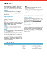
Refer to Figure A-1 for decal located adjacent to water
connections.
FIGURE A-1
Be certain that no leaks exist when the cooler is
turned on. A leak will deplete reservoir volume,
causing poor cooling, performance and reducing
torch life.
Note: Be certain that only 5/8-18 left handed male
nuts with clean and smooth threads are used on
your water hoses. Poor connections cause
coolant to leak at the fittings and will deplete the
coolant in the reservoir.
------------------------------------------------------------------------
If you have hose to make replacement hose assem-
blies but need to order the fittings and hardware, see
below for the correct part numbers to mate with the
Under-Cooler cart and the Precision TIG Machine.
Then follow the given instructions.
(2) T15007-2 Connector Nuts
(2) T15008 Nipples for 3/16" I.D. hose
(2) S10888-35 Hose Clamps
Remove the connector nut from the INLET hose by
making a straight cut 1/4"-1/2" (6-12mm) away from
the end of the nipple located inside of the hose. Take
the nipple and the connector nut ordered above and
insert the nipple into the connector nut so that the
threaded end of the connector nut points away from
the barbed end of the nipple. Twist the barbed end of
the nipple into the hose until the shoulder of the nipple
is flush with the end of the hose. Secure the hose onto
the nipple with the hose clamp to insure that the con-
nection is watertight. No water can leak from the con-
nection if it is properly attached. Repeat the procedure
for the OUTLET hose. When complete, follow the con-
nection procedure detailed above for connecting the
hoses to the cooler drawer fittings.
*The connector and nipple listed fit tightly onto 5/32"
(4.0mm) to 3/16" (4.8mm) inner diameter hose, but if
clamped tightly to the hose, can fit up to a .25
(6.4mm) inner diameter hose.
NOTE: Hoses have been provided with this product
and any replacement hoses, purchased or made,
should not deviate from their length. To replace the-
ses hoses from Lincoln Electric ORDER (1) S18453-
19 (HOT) AND (1) S18453-20 (COLD). Hoses too
long may be pinched when replacing the gas bottles
and hoses too short may be damaged opening the
cooler drawer.
CAUTION
CAUTION
COOLANT
OUT
COOLANT
IN
S25134

A-4
INSTALLATION
UNDER-COOLER CART
A-4
INPUT POWER CONNECTION
Plug the input power cord on the Under-Cooler cart
into the standard bottom 115V NEMA circuit breaker
protected receptacle, located on the back of the
Precision TIG machine. Using this receptacle is taking
advantage of the "cooler as needed" circuit incorporat-
ed into the TIG machine and will prolong the life of the
cooler. The lower, or bottom receptacle is clearly
marked for this application.
If you wish to use the top 115 V NEMA receptacle
located on the back of the machine for cooler opera-
tion, the cooler will run 100% of the time that the
Precision TIG machine is powered "ON".
ASSEMBLY OF PRECISION TIG
SAFETY PRECAUTIONS
• Protect yourself and others from serious injury
ELECTRIC SHOCK Can Kill
• Disconnect input before servicing.
• Do not touch electrically live parts.
• Do not touch live parts
• Only qualified persons should perform this
installation.
• This Undercarriage is designed to handle up to
two gas Cylinders.
• After Installation, check all mounting hardware to
assure tightness.
• Never use Lift Bale when Undercarriage and
Upper Cylinders Supports are attached.
• Keep all Gas Cylinders, placed on Cylinder
Platform, tightly chained to Upper Cylinder
Support!
CYLINDER may explode if damaged.
• Gas under pressure is explosive.
Always keep gas cylinders in an
upright position and always keep
chained to undercarriage or stationary
support.
• Cylinders should be located:
1. Away from areas where they may be
struck or subjected to physical damage.
2. A safe distance from arc welding or cut-
ting operations and any other source of
heat, sparks or flame
• Never lift a welder with a cylinder attached.
• Never allow welding electrode to touch cylinder.
• Read and follow the instructions on compressed
gas cylinders, associated equipment and CGA
publication P-1, “Precautions for Safe Handling of
Compressed Gases in Cylinders,” available from
the Compressed Gas Associate.,1235 Jefferson
Davis Highway, Arlington VA. 22202
Assembly of the Under-Cooler cart to the Precision
TIG machine is actually quite simple. Read carefully
the prior warnings and precautions to assembling to a
Precision TIG machine.
Assembly:
1. Lift the Precision TIG machine approximately 24"
(610mm) off the floor using the lift bale. Lower onto
the Under-Cooler cart aligning holes in the TIG base
with the two pins on each side of the Under-Cooler
cart roof.
2. Fasten the case sides of the Under-Cooler cart to
the TIG machine base using items 4 through 7 in
the 4 locations shown. Washer, lock washer and
nut, (in that order) are to be inside machine base
flange with the head of the bolt on the outside of the
Under-Cooler cart case side.
3. Remove (4) 5/16-18 X .625 long screws from the
front of the machine and discard. Mount handle with
the (4) remaining item 4 screws.
4. Lay the upper cylinder support and hook assembly
on top of the rear baffle and filler rod holder aligning
the top holes. Fasten in (4) places with item 8
screws as shown.
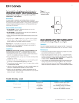
5. Add items 9 through 12 to the lift bale as shown to
prevent use of the lift bale with when gas bottles
have been loaded. See figure A-2 below.
FIGURE A-2
K1828-1 Under-Cooler Cart: Installation Instructions
Items Part Number Description Req”d
1 G3941 Under-Cooler Cart 1
2 M19767 Upper Cylinder Support 1
and Hook Assembly
3 L11682 Handle 1
4 S9225-47 5/16-18 x 1.50 Thread 8
Forming Screw
5 CF000029 5/16-18 Hex Nut 4
6 E106A-14 5/16 Lock Washer 4
7 S9262-121 5/16 Plain Washer 4
8 S9225-68 1/4-20 x .50 Thread 4
Forming Screw
9 CF000030 1/2-13 x 1.25 Hex Head 1
Cap Screw
10 S9262-62 1/2 Plain Washer 2
(2.25 O.D.)
11 E106A-15 1/2 Lock Washer 1
12 CF000027 1/2-13 Hex Nut 1
WARNING
1
2
3
4
4
5 6 7
8
9101112

A-5
INSTALLATION
UNDER-COOLER CART
A-5
CONNECTION OF TIG TORCHES
Installation of TIG torches to be used with this
Precision TIG Under-Cooler cart is explained in the
Precision TIG machine literature. The torch does not
directly attach to the cooler but through a connection
box mounted on the TIG machine.
-12-
-9-
-4-
-8-
-10-
-11-
-5- -6-
-7-
FASTENER QUICK REFERENCE
(FULL SCALE)
SEE FIGURE A-2 Assembly for fastener placement.

B-1
OPERATION
UNDER-COOLER CART
B-1
SAFETY PRECAUTIONS GENERAL DESCRIPTION
The Under-Cooler cart is an internal type, re-circula-
tion cooling system designed for use with water-
cooled TIG torches. The coolant "IN" and "OUT" con-
nections are 5/8-18 left-hand female threads which
match the standard connector nut of domestic water
hoses (CGA style) and water-cooled TIG torches.
The Under-Cooler cart can either run with the "cooler
as needed" circuit, which operates in conjunction with
the TIG machine fan, or continuously, powered on and
off with the TIG machine power switch.
The overall size and shape of the Under-Cooler cart is
designed for mounting the Precision TIG 275 / 375
machine on top. The Under-Cooler cart plugs into a
115 V power receptacle in the rear of the machine and
is rated for both 50 or 60 HZ. Adding coolant to the
reservoir is simple and connecting to the coolant "IN"
and "OUT" connections are easily made with an
adjustable wrench.
The Under-Cooler cart coolant flow is circulated
through a heat exchanger to remove heat energy from
the coolant. The coolant flow is then deposited into
the coolant reservoir. The pump draws its coolant sup-
ply from the coolant reservoir and delivers coolant to
the welding torch. Refer to Flow Diagram Section F.
DO NOT USE A WATER SOLENOID VALVE with
the Under-Cooler Cart.
-----------------------------------------------------------------------
RECOMMENDED PROCESSES
The Under-Cooler Cart is designed for use with the
Precision TIG 275 and Precision TIG 375 machines.
The recommended 115 V power receptacle is labeled
"cooler as needed". This receptacle shuts on and off
in conjunction with the TIG machine fan. By using this
receptacle, the duty cycle of the cooler is greatly
reduced and lets the cooler run only when needed.
RECOMMENDED EQUIPMENT
The Under-Cooler cart is designed for use with the
Precision TIG 275 and Precision TIG 375 and any
water cooled TIG Torches applicable. Although the
cooler could operate as a standalone unit, the cart has
been designed specifically to mount these two TIG
machines only.
ELECTRIC SHOCK can kill.
• Disconnect input power by remov-
ing plug from receptacle before
working inside Cooler.
• Do not operate with covers
removed.
• Use only grounded receptacle.
• Do not remove the power cord ground prong.
• Do not touch electrically “hot” parts inside
Cooler.
• Have qualified personnel do the installation,
maintenance and troubleshooting work.
• Never operate the cooler with the cooler drawer
opened except to temporarily check coolant
flow in the reservoir.
• Unplug the cooler before performing general
maintenance without removing drawer.
• High voltage typical of welding operations can
kill.
• Immersion in water around electrical lines can
cause electrical shock.
• Moving parts can injure. Never place fingers
into openings of Cooler.
• Unplug the cooler and remove water hoses to
remove drawer from the cabinet for mainte-
nance purposes. A jumper hose between the
coolant in and out connections should be
installed to avoid excessive loss of coolant in
the system.
• Never operate the cooler with the reservoir fill
cap off.
• Hot coolant can burn skin. Always be sure
coolant is NOT HOT before servicing the cooler.
• Do not pour used ethylene glycol coolant down
the drain.
• Do not remove the pump relief valve's 3/4" hex
nut or attempt to adjust the relief valve setting.
---------------------------------------------------------------------
See additional warning information at
front of this operator’s manual.
-----------------------------------------------------------
WARNING
CAUTION

B-2
OPERATION
B-2
TURNING THE SYSTEM "ON"
After connecting the Precision Tig and Tig
Torches per Installation Section, plug the unit into
a 115V NEMA electrical receptacle for start-up
operation. Be certain that the power input into the
unit matches the Cooler's rated input.
The following should always be observed when
operating the Under-Cooler Cart:
• Check the coolant reservoir level daily.
• Keep the reservoir full especially after changing
any water lines.
• The cooler should turn on as soon as an arc is
struck and remain on approximately 8 min. after
welding is stopped.
• Be certain that the cooler is ON by checking the
flow under the fill cap.
• Never operate the cooler with the reservoir fill
cap removed after checking the flow.
• Avoid placing the Under-Cooler Cart and TIG
Welder near a flux hopper or an area where dust
build-up is extreme.
• Avoid kinking or putting sharp bends in any
water lines.
• Keep all water lines clean and free of any block-
age.
• Do not operate cooler without coolant in reser-
voir. Never run pump dry.
• Never lift the Precision TIG by its lift bale once
the under-cooler cart has been installed.
• Never lift the Precision TIG and Under-Cooler
cart by its handle.
-----------------------------------------------------------------------
You will be able to hear the fan running and feel air-
flow out of the back of the unit when the cooler is
operating. The cooler will run continuously unless it is
plugged into the switched receptacle on the power
source (bottom 115V receptacle).
The coolant FLOW INDICATOR is accessed by
removal of the fill cap. Actual return flow is directly vis-
ible, via the fill opening of the reservoir with the draw-
er open. SHUT THE COOLER DRAWER DURING
NORMAL OPERATION.
When first starting the unit, check all of the coolant
hoses to insure that no water leaks are present.
Water leakage causes poor welding performance,
poor cooling performance, low welding component life
and potential electrical safety hazards.
COOLING EFFICIENCY
The high cooling efficiency of the Under-Cooler cart
offers a cooler, more comfortable weld than conven-
tional air-cooled procedures as well as leading com-
petitors water cooled systems.
The Under-Cooler cart effectively removes the heat of
the arc away from the torch handle and places it into
the exiting air flow at the back of the Cooler. Ambient
air temperature affects the coolant temperature of the
cooler.
Unlike other water coolers that depend on bulky reser-
voir size, the high efficiency components of the Under-
Cooler cart allows the reservoir size to be small. The
result is a lightweight unit, in a drawer with additional
storage space for welding accessories.
UNDER-COOLER CART
CAUTION

D-1
MAINTENANCE
D-1
PUMP
The pump head has a "built in" strainer on the inlet
side of the pump. It is recommended to clean or
replace the pump’s inlet strainer at least annually
as follows:
• Drain the coolant reservoir and all coolant lines.
Dispose of the coolant properly as specified above.
• Hold the pump head firmly to apply a counter-torque
when loosing the strainers 7/8" acorn nut located on
the bottom. Do not confuse with 3/4" acorn nut.
Remove nut and slide inlet strainer down and out
from the pump head.
• Gently rinse the strainer under running water to
thoroughly clean it.
• Use a mirror to inspect the inside of the pump for
contamination. Carefully remove hardened debris
with a dental pick if necessary, without scratching
the inside of the pump.
• Reinstall the strainer and 7/8 acorn nut, tighten to 75
in-lbs.(8.5N-m) of torque. Wipe dry all area wetted
with coolant. Dispose of coolant soaked towels
properly as specified above.
PUMP MOTOR
The Under-Cooler cart is rated for continuous
operation. It is recommended to re-oil the pump
motor bearings once a year as follows:
• Remove the plastic plugs located on the top of both
the inboard and outboard bearing end-caps.
• Re-oil each bearing with 30-35 drops of SAE 20 oil
then reinstall both plugs.
HEAT EXCHANGER
To maintain maximum cooler efficiency, the heat
exchanger should be kept free of dust and dirt build-
up. Clean the heat exchanger periodically using a
vacuum hose or a low-pressure air line. Avoid placing
the unit near a flux hopper or a flux waste container.
A clean heat exchanger offers better cooling perfor-
mance and longer product life. In extremely dirty
environments, it may be necessary to remove the
heat exchanger completely from the cooler and clean
the fins with soap and water. Use care to avoid
damaging the fins.
UNDER-COOLER CART
SAFETY PRECAUTIONS
Have qualified personnel do the maintenance
work. In some cases, it may be necessary to
remove safety guards to perform required
maintenance. Remove guards only when
necessary and replace them when the mainte-
nance requiring their removal is complete.
Always use the greatest care when working near
moving parts.
-----------------------------------------------------------------------
ELECTRIC SHOCK can kill.
• Do not touch electrically live parts or
electrode with skin or wet clothing.
• Insulate yourself from work and
ground
• Always wear dry insulating gloves.
------------------------------------------------------------------------
MOVING PARTS can injure.
• Do not operate with doors open or
guards off.
• Keep away from moving parts.
------------------------------------------------------------------------
Observe all Safety Guidelines detailed throughout
this manual. Be sure to disconnect the Under-
Cooler cart from the Power Source before
performing any maintenance procedures.
---------------------------------------------------------
ROUTINE
Remove accumulated dust and dirt from the internal
components of the cooler by blowing it out with a low-
pressure air hose or removing it with a vacuum hose.
PERIODIC
In dirty or dusty environments or if biological growth
occurs in the coolant, it may be necessary to flush the
coolant reservoir. Dump the old coolant, rinse the
inside of the reservoir and circulate rinsing solution
through coolant system. Add new coolant when
cleaning is finished. It is recommended to flush the
coolant at least once a year. A cooling system free
from debris offers increased cooling efficiency and
longer pump and torch life. See the coolant treatment
recommendation in “Section D-2”.
NOTE: Pure solutions and mixtures of, or materials
(i.e. towels) wetted with ethylene glycol are toxic to
humans and animals. They must not be haphazardly
discarded, especially by pouring liquids down the
drain. Contact the local EPA office for responsible
disposal methods or for recycling information.
WARNING

D-2
MAINTENANCE
D-2
RESERVOIR COOLANT LEVEL
The reservoir volume should be checked daily before
using the cooler. Remove the reservoir fill cap and
check the coolant level. The reservoir is full when the
coolant level is just below the input elbow of the reser-
voir (approximate. 2 Gal / 7.6 ltrs). Keep the reservoir
full, especially after disconnecting the water lines or
changing the accessory being cooled.
COOLANT TREATMENT
RECOMMENDATION
This procedure is intended to provide a means of
reducing the objectionable amount of fungal and bac-
terial contamination that has occurred in Under-Cooler
cart water coolers and cooling systems.
Limitations:
• This additive should be used with fresh coolants con-
taining only pure water.
• This additive should not be used with coolants con-
taining any other substance, including antifreeze
substances.
• No other additives shall be used with the specified
coolant that has been treated with the recommended
additive.
• This procedure is no permanent substitute for a peri-
odic maintenance schedule for the specified coolers
• A 1 quart bottle of additive is sufficient to disinfect
and treat about 720 coolers.
• Check with the manufacturer of your guns or
torches to be sure that this procedure is compat-
ible with your equipment.
a. Additive: "Poly Algaecide 30X" containing 30% of
active ingredient Poly oxyethylene (dimethylimino)
ethylene (dimethylimino) ethylene dichloride.
b. Cooler: Lincoln part number see Parts Pages of
this manual.
c. Cooling system: the entire system, including cool-
er and accessories (torch, all connecting hoses,
etc.)
d. Disinfectant: A user-prepared mixture of fresh,
pure water and additive concentrated to 200 ppm
maximum.
e. ppm: parts per million
f. Treated coolant: A user-prepared mixture of fresh,
pure water and additive concentrated to a nominal
of 30 ppm
Preparation:
• Always switch off the Precision TIG machine power.
• Always disconnect the Under-Cooler cart from the
TIG machine receptacle.
• Be sure that the coolant presently in the system is at
room temperature to avoid being burned.
• Personal safety equipment: chemical safety glasses,
rubber gloves.
• See applicable MSDS for additional information.
• Contact the additive manufacturer, local EPA office
or applicable environmental agency for responsible
disposal methods of both used, treated coolant and
used disinfectant.
• Safety hazards are identified in equipment instruc-
tion manuals: refer to specific Power Source
machine manual and Under-Cooler cart IM723.
Drain the cooling system of contaminated coolant:
• Do not reuse this coolant.
• If system contained an antifreeze-based coolant,
rinse the cooling system until it is clear of antifreeze
solution.
Service the cooler:
• Always unplug the cooler and remove hoses con-
nected to the TIG machine. Remove the cooler
drawer for thorough cleaning and disinfecting of sys-
tem.
• Independently flush out the welding accessories of
debris if necessary
• Mechanically clean out the cooler, including reser-
voir, of debris if necessary. Power washing may be
useful.
• Clean or replace the pump’s inlet strainer as
required
UNDER-COOLER CART

D-3
MAINTENANCE
D-3
Disinfect the cooling system:
• Prepare the disinfectant: Make a quantity of only is
needed to avoid an excess.
• Bulk preparation (for coolers serviced in quantity):
2.325 gals. (8.775 liters) of pure, fresh water per
cooler 1.625 ml of additive per cooler
• Example: for 100 coolers, add 162.5 ml to 232.5
gals. of pure fresh water Pour 2.0 gals. (7.55 liters)
of disinfectant into the empty reservoir
• Recap the reservoir, tape over the air vent in the
cap, roll disinfectant around the inside the reservoir
to thoroughly coat all of its surfaces.
• Remove the tape from the reservoir cap. Prime the
cooling system and circulate disinfectant through it
for 10 to 15 minutes.
• Drain disinfectant from the cooling system. Do not
reuse this solution.
• Add new, fresh coolant to the cooling system. Add
0.325 gals. (1.225 liters) of fresh disinfectant to the
system by pouring it into the reservoir, then reduce
the concentration to the nominal 30 ppm:
• Add the balance 1.675 gals. (6.325 liters) of fresh,
pure water to the reservoir to create the treated
coolant concentration
• Prime the cooling system
• Check coolant level. Add more fresh, pure water if
required, without adding more than 0.125 gal. (0.475
liters) of pure water to prevent diluting the coolant
additive.
Additive:
The recommended additive can be purchased at local
pool supply stores. An example is "Maintain Pool Pro
30% Non-Foam Algaecide".
PUMP INLET FILTER
Poor cooler performance can usually be traced to a
partially or completely blocked pump inlet filter. This is
a user-serviceable item and can be cleaned and
reused, or replaced. Continued pump operation with a
blocked filter can cause:
• Voiding of cooler service warranty
• Cavitation damage to the pump heads inlet areas
• Welding accessory damage from overheating due to
insufficient coolant flow rate.
A new or properly cleaned pump inlet filter should
restore the cooler’s performance.
For additional service and periodic maintenance
details and for recommended coolants, follow the rec-
ommendations listed in the following paragraphs.
PROCEDURE
Preparation:
• Always switch off the Precision TIG machine power
• Always disconnect the Under-Cooler cart from the
Tig machine receptacle.
• Always allow the coolant in the system to cool
enough to avoid burn injuries.
• Avoid contact with contaminated coolant. Wear
waterproof gloves and protective eyewear.
• Do not remove the pump relief valves 3/4 in. acorn
hex nut or attempt to adjust the relief valve setting.
Inspect condition of coolant:
a. If coolant is contaminated or old:
• Drain the system of coolant and dispose of it in an
environmentally responsible manner.
• Flush system of old coolant.
• Fill with fresh tap or distilled water, run for ten min-
utes, and drain.
• Proceed to adding coolant.
b. If coolant is clean and fresh:
• If clean, dedicated coolant handling equipment,
including a clean siphon pump and a clean holding
tank are available then proceed to servicing the
pump inlet strainer.
Removing Coolant:
a. Drain coolant from the reservoir using clean
siphoning equipment.
b. Coolant level should be drained below the filter’s
pressure fitting:
• This prevents coolant from streaming out of unit
when filter nut is removed.
UNDER-COOLER CART

D-4
MAINTENANCE
D-4
Service the pump’s inlet strainer:
a. Place absorbent towels underneath pump head to
prevent stray coolant from wetting cooler’s electrical
components.
b. Hold pump head to apply counter torque when loos-
ening strainers 7/8 acorn nut. Do not confuse with
3/4 acorn nut. Remove nut and slide inlet strainer
down and out from pump head. See figure 3A.
c. Inspect strainer for damage or excessive clogging:
• Replace or Gently rinse strainer under running
water to thoroughly clean it
d. Use a mirror to inspect inside of pump for contami-
nation. If hardened debris is present and interferes
with filter seating, carefully remove it with dental
pick without scratching inside of the pump. Use
care not to drop debris into pump.
e. Reinstall strainer and acorn nut, tighten to 75 in-
lbs.(8.5N-m) of torque. Hold pump head to apply
counter-torque when loosening strainers 7/8 acorn
nut.
f. Wipe dry all areas wetted by coolant. Dispose of
towels in an environmentally responsible manner.
Add coolant:
• Add 2 Gal. ( 7.6 ltrs.) of coolant, either the recom-
mendations off the water cooled accessory or if
none, see the design specification summary listed in
this manual.
ADDITIONAL SERVICE NOTES:
• Always use a back-up wrench on pump head when
loosening or tightening pump fittings.
• Never run the pump dry. Always use a recommend-
ed coolant, otherwise pump damage may result.
• Flush coolant from system and replace with
fresh, recommended coolant at least once a
year. More frequent flushing may be necessary,
depending upon the user’s particular system or
its usage, especially if it is prone to clogging
from biological growth in the coolant.
UNDER-COOLER CART

E-1
TROUBLESHOOTING
E-1
UNDER-COOLER CART
If for any reason you do not understand the test procedures or are unable to perform the tests/repairs safely, contact your
Local Lincoln Authorized Field Service Facility for technical troubleshooting assistance before you proceed.
CAUTION
This Troubleshooting Guide is provided to help you
locate and repair possible machine malfunctions.
Simply follow the three-step procedure listed below.
Step 1. LOCATE PROBLEM (SYMPTOM).
Look under the column labeled “PROBLEM (SYMP-
TOMS)”. This column describes possible symptoms
that the machine may exhibit. Find the listing that
best describes the symptom that the machine is
exhibiting.
Step 2. POSSIBLE CAUSE.
The second column labeled “POSSIBLE CAUSE” lists
the obvious external possibilities that may contribute
to the machine symptom.
Step 3. RECOMMENDED COURSE OF ACTION
This column provides a course of action for the
Possible Cause, generally it states to contact your
local Lincoln Authorized Field Service Facility.
If you do not understand or are unable to perform the
Recommended Course of Action safely, contact your
local Lincoln Authorized Field Service Facility.
HOW TO USE TROUBLESHOOTING GUIDE
Service and Repair should only be performed by Lincoln Electric Factory Trained Personnel.
Unauthorized repairs performed on this equipment may result in danger to the technician and
machine operator and will invalidate your factory warranty. For your safety and to avoid Electrical
Shock, please observe all safety notes and precautions detailed throughout this manual.
__________________________________________________________________________
WARNING

E-2
TROUBLESHOOTING
E-2
UNDER-COOLER CART
Observe all Safety Guidelines detailed throughout this manual
If for any reason you do not understand the test procedures or are unable to perform the tests/repairs safely, contact your
Local Lincoln Authorized Field Service Facility for technical troubleshooting assistance before you proceed.
CAUTION
PROBLEMS
(SYMPTOMS)
POSSIBLE AREAS OF
MISADJUSTMENTS
RECOMMENDED
COURSE OF ACTION
Cooler does not operate
Internal water leak.
Torch or gun runs hot.
Fan operates but there is low
coolant flow.
Fan operates but there is no
coolant flow.
Pump operates, but fan does not.
1. Input cord unplugged.
2. Power harness damaged.
3. Water lines blocked or crimped.
4. Leak in gun or water hoses.
5. Coolant reservoir empty.
6. The system needs to be primed.
1. Hose clamp loose on one of
internal hoses.
2. Internal hose punctured.
3. Heat exchanger leaking.
4. Pump seal is leaking.
1. Unit placed by area of extreme
heat.
2. Low coolant flow.
3. No coolant flow.
4. Fan not operating.
5. Heat exchanger clogged.
6. Pump seal is leaking
1. Leak in torch/gun or hoses.
2. Torch/gun or hoses partially
obstructed.
3. Reservoir empty or very low.
4. Pump Strainer is dirty.
1. Pump or pump motor failure.
2. Pump strainer is blocked.
1. Loose or disconnected fan lead.
2. Obstruction in fan blade.
3. Fan motor failure.
If all recommended possible areas
of misadjustment have been
checked and the problem persists,
Contact your local Lincoln
Authorized Field Service Facility.

F-1
WIRING DIAGRAM
F-1
UNDER-COOLER CART
NOTE: This diagram is for reference only. It may not be accurate for all machines covered by this manual. The specific diagram for a particular code is pasted inside
the machine on one of the enclosure panels. If the diagram is illegible, write to the Service Department for a replacement. Give the equipment code number..
M19812
UNDER-COOLER CART
ELECTRICAL SYMBOLS PER E1537
COLOR CODE: B - BLACK OR GRAY
W - WHITE
G - GREEN
G1 -
BASE GROUND CONNECTION
G2 - FAN SHROUD GROUND
CONNECTION
P1 - INPUT POWER PLUG
MTR1 - PUMP MOTOR
MTR2 - FAN MOTOR
W
W
G
W
B
B
B
B
W
1
4
MTR1
MTR2
G2
G1
INPUT: 115 V
50/60 HZ
P1
W
D
/