
INSTALLATION GUIDE EN
PELLET STOVE
SUITE/CLUB/MUSA 2.0
air - comfort air
PART 2 - OPERATION AND CLEANING
Instructions in English

II
TABLE OF CONTENTS
TABLE OF CONTENTS .................................................................................................. II
10FIRST STARTUP .....................................................................................................3
11REMOTE CONTROL MAX ..........................................................................................4
12EMERGENCY PANEL ..............................................................................................11
13OPERATION .........................................................................................................13
14SAFETY DEVICES ..................................................................................................15
15ALARMS ..............................................................................................................17
16RECOMMENDATIONS FOR SAFE USE .......................................................................19
17CLEANING ...........................................................................................................20
18FAULTS/CAUSES/SOLUTIONS .................................................................................27
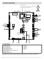
19AIR STOVE CIRCUIT BOARD ...................................................................................30
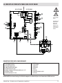
20COMFORT AIR STOVE WITH THREE FANS CIRCUIT BOARD.........................................31

3
10-FIRST START-UP
Technical Dept. - All rights reserved - Reproduction is prohibited
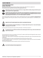
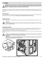
PRECAUTIONS BEFORE START-UP
GENERAL PRECAUTIONS
Remove all parts that may burn from the brazier and the glass (manual, various adhesive labels or any polystyrene).
Check that the brazier is positioned correctly and rests properly on the base.
The rst start-up may not be successful as the feed screw is empty and does not always manage to load the required
amount of pellets in time to light the ame.
ELIMINATE THE ALARM CONDITION OF A FAILED START-UP BY POSITIONING THE OF THE EMERGENCY PANEL TO OFF FOR
ABOUT 20 SECONDS AND BRINGING SELECTOR “D” BACK TO THE REMOTE POSITION. REMOVE THE PELLET LEFT IN THE
BRAZIER AND REPEAT THE START-UP. (SEE “SAFETY DEVICES/ALARMS” PARAGRAPH)
If after repeated attempts, the ame fails to ignite, despite a regular ow of pellets in the brazier, which must rest snugly against the
slots. If no anomaly is found during this inspection, there may be a problem with the product components or installation may not be
correct.
REMOVE THE PELLETS FROM THE BRAZIER AND CONTACT AN AUTHORISED TECHNICIAN.
Do not touch the boiler during the rst lighting, as it is during this phase that the paint sets. If you touch the paint,
you may expose the steel surface.
If necessary, touch up the paint with the spray can of the specic colour. (See “Pellet stove accessories”)
It is good practice to ensure eective ventilation in the room during the initial start-up, as the boiler will emit some
smoke and smell of paint.
Do not stand close to the stove and, as mentioned, air the room. The smoke and smell of paint will disappear after about an hour of
operation, however, they are not harmful in any case.
The boiler will be subject to expansion and contraction during the lighting and cooling down stages, and may therefore make slight
creaking noises.
This is absolutely normal as the structure is made of laminated steel and must not be considered a defect.
It is extremely important to make sure the boiler does not reach high temperatures straight away, but to increase the temperature
gradually using low power at rst.
This will prevent damaging the ceramic or serpentine stone tiles, the welds and the steel structure.
DO NOT EXPECT HEATING EFFICIENCY IMMEDIATELY!!!

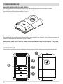
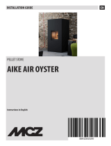
A
B
E
C
D
4
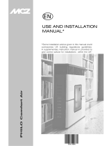
11-REMOTE CONTROL MAX
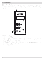
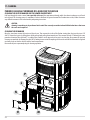
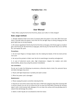
GENERAL FEATURES OF THE LCD REMOTE CONTROL
The remote control works at a transmission frequency of 434.5 MHz. Power the product with 3 AAA batteries as follows:
Remove the battery compartment cover by pressing and lifting according to the arrow
Insert the batteries observing the correct polarity (+) and (-)
Close the battery compartment cover.
When the remote control is powered it automatically prompts to set the time.
The remote control has a special icon on the display to indicate when the batteries are almost at. If the at battery icon appears, the
batteries are almost at and the remote control is about to switch o.
Used batteries contain metals which are harmful to the environment, so they must be disposed of separately in
appropriate containers.
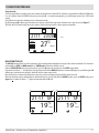
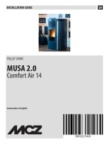
GRAPHIC APPEARANCE
In the instructions we will often refer to the indications of the keys shown in the gure. Always keep it at hand for simplicity’s sake.

MAN
12:02
31
MAX
°C
TU
12:03
31
°C
TU
35
°C
AUTO
5
11-REMOTE CONTROL MAX
Technical Dept. - All rights reserved - Reproduction is prohibited
REMOTE CONTROL OPERATION
General rules
By pressing key A for 1” the product is switched on and o. Key C is used to make all changes. Key E is used to conrm the changes. By
pressing key B one selects the product operating mode. Via key D one browses the FAN and SLEEP setting. Whichever the mode is, press
key A briey (or leave the keypad idle for 7”) to go back to the initial display.
INITIAL SETTINGS
Setting the time
Both with the remote control on and o, by pressing keys B+E at the same time for 3” one accesses the time/day setting mode.
The hour digits will start to ash; they can be changed with key C. By pressing key E the changes are conrmed.At this point the minutes
digits will start to ash.
Follow the same modify/conrm procedure, one will then go onto the time display mode (12h or 24h) and nally
the day will start to ash. Conrm this data to exit the settings.
NOTE: each time the remote control is powered, the time is reset and the display automatically enters the time setting mode.
°C – °F setting
Only with the stove switched o, by pressing key B for 5” one changes the unit of measure of the temperature, from Celsius to Fahrenheit
and vice versa.
SETTING THE OPERATING MODE
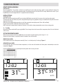
With the remote control switched on, key B allows to set one of the 4 product operating modes. Figure 1-2-3-4
displays the 4 basic displays, respectively: Manual, Automatic, Timer and Eco mode.
MANUAL Mode (MAN)
In this mode one can set the ame power manually (5 levels - act directly on key C to change). Figure 1
AUTOMATIC Mode (AUTO)
In this mode one can set the desired room temperature, and the stove will modulate the ame power automatically to reach the
temperature. Figure 2
If a fan is AUTOMATICALLY set, its speed depends on the power that is running the stove:
In the case of power level 1: V=1
In the case of power level 2: V=2
In the case of power level 3: V=3
In the case of power level 4: V=3
In the case of power level 5: V=3
FIG.1 FIG.2

MAN
12:02
31
MAX
°C
TU
6
11-REMOTE CONTROL MAX
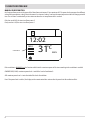
MANUAL POWER FUNCTION
this function allows you to set the power of the ame from a minimum of 1 to a maximum of 5. The power levels correspond to a dierent
value of fuel consumption, setting 5 heats the room in less time and setting 1 can keep the room temperature stable for a longer period of
time. The set ame is automatically set to a minimum when the set temperature value is reached.
if the bars are all full, the stove is on ame power 5
if only one bar is full, the stove is on ame power 1
If the ventilation is MANUALLY set, the function which limits the maximum power of the stove according to the ventilation is enabled.
COMFORT AIR (3 FANS): maximum power level = total of the levels of ventilation/2.
AIR: maximum power level = twice the total of the levels of ventilation
Even if the power limit is enabled, the display on the remote control does not consider the power limit for ventilation eect.
FLAME POWER

8:20
26
FR
20
°C
TIMER
°C
P1
12:06
31
°C
TU
23
°C
ECO
12:07
31
°C
TU
23
°C
TIMER
ECO
7
11-REMOTE CONTROL MAX
Technical Dept. - All rights reserved - Reproduction is prohibited
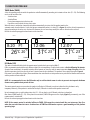
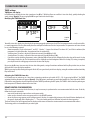
TIMER Mode (TIMER)
Select this operating mode to switch the product on and o automatically, according to 6 customised time slots (P1 – P6). The following
can be set for each time slot:
• Switch-on time
• Switch-o time
• Desired room temperature in the time slot
• Days of the week in which the time slot is active
When the stove is switched on (manually via key A or automatically via a time slot) the product works in the
automatic mode described above. A time slot appears automatically when it is active (P1 in gure 3) and the desired temperature is
changed according to the value set in the time slot. However, the user can always modify this value as desired and in real time.
Refer to the relevant paragraph to learn how to set the time slots.
ECO Mode (ECO)
This mode is activated/disabled with the remote control switched on by pressing key B for 5”.
ECO is an automatic mode with the only dierence that if the set temperature is reached and remains so for the following 20 minutes
(despite ame modulation), the product switches o and remains on stand-by until the room temperature drops 2 degrees below the
desired temperature (and in any case for at least 5 minutes from the last shutdown). The product is then switched on again. Figure 4
If the room is not suciently insulated, ame modulation does not allow the set temperature to stay satised for 20 consecutive minutes
and the product will not switch o.
NOTE: It is recommended to use the ECO mode only in well-insulated rooms in order to prevent start-up and shutdown
from occurring within short periods of time.
The remote control remains on even when the product is o when in ECO mode, in order to indicate that this shutdown is only
temporary. Obviously, if the product is switched o via key A, ECO mode is exited and the product remains o.
Up to 6 automatic start-up and shutdown time slots (E1 – E6) can also be set in ECO mode, which are independent
from those of TIMER mode (P1 – P6). If they have been activated, TIMER-ECO appears on the display (gure 5) permanently, even if the
remote control is switched o.
Refer to the relevant paragraph to learn how to set the time slots.
NOTE: If the remote control is switched o due to TIMER, ECO cannot be restarted until the user intervenes (key A) or
when the next valid time slot starts. Combined use of TIMER and ECO modes requires a good knowledge of the product
operating logic.
FIG.3 FIG.5FIG.4

26
°C
8
11-REMOTE CONTROL MAX
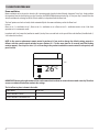
Room ventilation
Room ventilation can be adjusted as desired in all 4 operating modes described above (Manual, Automatic, Timer, Eco). Simply perform
this operation: from the basic display, press key D to access the VENTILATION adjustment mode (Fig. 6). Then press key C (arrows) to set the
desired ventilation by selecting one of the 5 levels available, independent from the ame level.
The “auto” option can also be selected, which automatically links the room ventilation speed to the ame level.
In short:
ame set on 1 > ventilation set on 1; ame set on 3 > ventilation set on 3; ame set on 5 > ventilation remains set on 3 (for silent
operation as it is in automatic mode).
In products with 2 or 3 room fans (comfort air models) via key D one can scroll and set the speed of the individual fans (identied with 1,
2 or 3 above the level bars).
NOTE: In the event a replacement remote control is purchased, if you need to change the default setting, proceed as
follows: with the remote control switched on press buttons D + E at the same time for 10 seconds (until the ashing
number appears). Press key C to select 1, 2 or 3 according to the product to which the remote control is to be paired, and
press E to exit.
IMPORTANT! Choosing the right number of fans can become a decisive factor to ensure the stove works correctly. Therefore
ensure an authorised technician conducts the settings.
The list of fans in place is shown in the table:
STOVE MODEL NO. OF FANS
SUITE/CLUB/MUSA 2.0 AIR 1
SUITE/CLUB/MUSA 2.0 COMFORT AIR 3
FIG.6

MAN
21:11
FR
OFF
27
23:00
MAX
°C
MAN
21:11
FR
19
SF
°C
MAN
21:11
FR
19
SF
°C
9
11-REMOTE CONTROL MAX
Technical Dept. - All rights reserved - Reproduction is prohibited
Sleep function
The sleep mode allows to quickly set the time at which the product must switch o. This function is only available in MAN and AUTO mode.
It is set as follows: from the POWER setting (by pressing key D - see previous paragraph), press key D again to access the SLEEP mode
setting.
Via key C one can adjust the shutdown time in 10 minute intervals.
By conrming with D or E one goes back to the basic display, in which the sleep mode shutdown time is any case visible (gure 7).
To disable the SLEEP mode simply access the settings, decrease the time until the dashes appear and conrm.
NO AIR FUNCTION (SF)
The NO AIR function allows the stove to operate at the minimum power throughout the night, with no room ventilation. This function is
only available in AUTO and MAN mode(not in TIMER mode). Proceed as follows to set it:
from the VENTILATION setting (by pressing key D), press key D again and you will access theSLEEP setting mode.
From when the dashes “--“ are displayed, press the lower key C and the NO AIR function is activated (SF appears); by conrming with D
or E one goes back to the basic display in which SF and the moon remain visible.
Once the function is activated, the ame power goes to 1 and the ventilation switches o after about 5 minutes.
When this function is active, nothing happens when the C keys are pressed. To disable the NO AIR function, access the SLEEP setting, press
upper key C to make the dashes “--“ appear and conrm with keys D or E.
FIG.7

TIMER
6:30
8:00
MO
TU
WE
TH
FR
SA
SU
ON
OFF
20
P1
°C
TIMER
ECO
OFF ON
10
11-REMOTE CONTROL MAX
TIMER settings
TIMER time slot display
In TIMER mode, to display the time slots simply press key D for 2”. With key C one can scroll the 6 time slots freely, quickly checking the
saved settings (gure 8). By pressing key D or A one goes back to the basic display.
Modifying the TIMER time slots
To modify a time slot, display it as described in the previous paragraph and then press key E. The rst parameter to be set will start to ash,
i.e. room temperature. Press key C to modify the value and key E to conrm and set the next parameter. The parameters of a time slot can
be set in the following sequence:
• Room temperature. Can be set between 5° and 35°C. 2 dashes “--” appear if set below 5°C or above 35°C, and if this is conrmed, the
programme is disabled(therefore, the product will not be switched on).
• Switch-on time. The value is adjusted in 10 minute intervals (from 00:00 to 23:50)
• Switch-o time. The value is adjusted in 10 minute intervals (from 00:10:00 to 24:00).
• Days of the week in which the programme is active. Monday (MO) will start to ash, followed by the other days of the week. Use key
C to activate/disable the day. The activated days will be displayed on a dark background. When the Sunday (SU) setting is complete,
press key E to exit the editing page and return to the time slots display.
By pressing key D at any time one exits the time slot editing mode, saving all variations conrmed with key E up to that time, and one
goes back to the time slot display condition.
While by pressing key A (or leaving the keypad idle for 30”) one goes directly to the basic display, saving all variations conrmed with key
E up to that time.
Activating the TIMER-ECO time slots
In ECO mode one can activate up to 6 time slots, customising switch-on and switch-o (E1 – E6): by pressing key D for 2” the TIMER
activation/disabling function will appear (gura 9). If the ON option is conrmed one can display/modify the 6 time slots of the TIMER-
ECO with the same procedure described previously for the TIMER. By conrming the OFF option, the TIMER is disabled and the product goes
back to operate in ECO mode without active time slots.
REMOTE CONTROL SYNCHRONIZATION
When the product is started up for the rst time, it may be necessary to synchronize the new remote control with the stove. To do this,
follow these simple instructions:
• connect the socket to the stove and turn on the power switch
• make sure the selector D on the emergency panel is in the REMOTE position
• when the rst message appears on the emergency panel’s display, use a pointed object to press the chased G button (toothpick, etc.)
• the panel’s display will show 3 ashing lines “---“. Press the remote control’s on/o button to launch the learning process.
The three ashing lines will disappear from the display and the stove will learn the remote control’s new communication address.
The learning process is also conrmed by an audio signal.
FIG.9
FIG.8

A
B
C
G
D
E
F
11
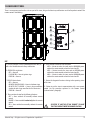
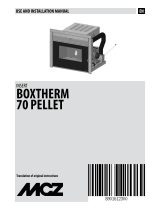
12-EMERGENCY PANEL
Technical Dept. - All rights reserved - Reproduction is prohibited
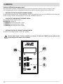
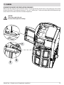
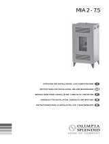
There is an emergency panel on the side-rear part of the stove, designed to detect any malfunctions and also for product control if the
remote control is not working.
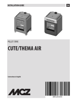
KEY
A - DISPLAY; indicates a series of information on the stove, as
well as the identication code of any malfunction.
B - GREEN LED that indicates:
• OFF = Stove o
• FLASHING ON = Stove in ignition stage
• FIXED ON = Stove on
C - RED LED that indicates:
• OFF = Stove on
• ON WITH SLOW FLASHING = Stove in shutdown stage
• ON WITH FAST FLASHING = Stove in alarm conditions
(combined with a beep sound for the rst 10 minutes)
• FIXED ON = Stove o
D - Three-position selector for the following functions
• OFF = Stove switched o manually without remote
control
• REMOTE = Stove controlled exclusively from the remote
control
• ON = Stove switched on manually without the remote
control
E - Three-position selector to select the power
• MIN = Selector to make the stove work at MINIMUM power
without the remote control and with selector 4 on ON
• MED = Selector to make the stove work at MEDIUM power
without the remote control and with selector 4 on ON
• MAX = Selector to make the stove work at MAXIMUM power
without the remote control and with selector 4 on ON
F - Button for diagnostic functions relating to the operating status
of the stove
G - Button to put the stove in communication with a new remote
control (via the procedure explained in the Remote Control
Synchronisation" paragraph).
SELECTOR "D" MUST BE SET ON "REMOTE" TO MAKE
THE STOVE OPERATE WITH THE REMOTE CONTROL.

V
A
12
12-EMERGENCY PANEL
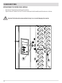
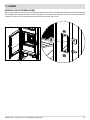
INSTALLATION OF THE CONTROL PANEL ANTENNA
• Take Antenna “A” from the bag containing the instructions
• Tighten Antenna “A” clockwise on screw “V” near the control panel until the mobile part of the antenna is at the top.
Attention! Fully tighten the antenna without forcing it so as to avoid damaging the reception.

I/ON
13
13-OPERATION
Technical Dept. - All rights reserved - Reproduction is prohibited
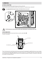
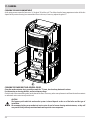
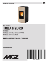
ELECTRICAL CONNECTION
First connect the power cable to the back of the stove and then to a wall socket.
The main switch must only be activated to switch the stove on; otherwise, it is advisable to keep it switched o.
It is recommended to disconnect the power cable when the stove is not used.
The cable must never come into contact with the smoke exhaust pipe or any other part of the stove.
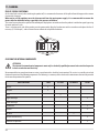
STOVE POWER SUPPLY
After connecting the power cable to the back of the stove, turn the switch to (I) or ON.
The stove is then powered.
There is a fuse box also in the switch block next to the power socket. Open this compartment by simply lifting the cover, using a screwdriver
as a lever from inside the power outlet compartment. Inside there are two fuses (3.15 A delayed), which may need to be replaced if the
stove is not powered (e.g. the ON/OFF button does not go on or the control panel display does not light up) - operation to be implemented
by an authorised and skilled technician.
ELECTRICAL STOVE CONNECTION
STOVE POWER SUPPLY
STOVE SWITCH
FUSE COMPARTMENT

ON
OFF
D
E
14
13-OPERATION
Switch-on/o from the emergency panel
If the remote control is faulty or the batteries are at, the product can be operated in safe mode via the rear emergency panel.
In this conguration, the stove can only operate in manual mode and with the possibility to choose between 3 power levels.
• SWITCHING THE STOVE ON WITHOUT THE REMOTE CONTROL
To switch the stove on move selector “D” to the ON position. The RED LED goes o upon start-up, while the GREEN LED starts to ash until
the start-up stage is complete. Once the product is in steady state, the GREEN LED remains on.
• CHOOSING THE POWER WITHOUT THE REMOTE CONTROL
One can choose between 3 heating powers:
MIN-MED-MAX (seletctor “E”)
The MINIMUM power corresponds to the 1
st
power;
The MEDIUM power corresponds to the 3
rd
power;
The MAXIMUM power corresponds to the 5
th
power;
• SWITCHING THE STOVE OFF WITHOUT THE REMOTE CONTROL
To switch the stove o move selector “D” to the “OFF” position.
Once the remote control is restored, remember to set selector “D” back to the “REMOTE” position, otherwise the
product will ignore the remote control commands.

15
14-SAFETY DEVICES
Technical Dept. - All rights reserved - Reproduction is prohibited
SAFETY DEVICES
The product is tted with the following safety devices.
SMOKE TEMPERATURE PROBE
It detects the temperature of the smoke, thereby enabling start-up or stopping the product when the temperature drops below the preset
value.
PELLET HOPPER TEMPERATURE PROBE
If the temperature exceeds the preset safety value, it immediately stops the product, which must cool down before the stove is restarted.
ELECTRICAL SAFETY
The product is protected against power surges by a general fuse located in the control panel on the back. Other fuses that protect the
electronic boards are found on the latter.
SMOKE FAN BREAKAGE
If the fan stops, the circuit board promptly blocks the supply of pellets and the alarm is displayed.
GEAR MOTOR BREAKAGE
If the gear motor stops, the product switches o and the relative alarm is signalled.
TEMPORARY POWER CUT
If a power cut occurs during operation, the product automatically sets itself in cooling mode when the power is restored and then it
restarts.
FAILED START-UP
If no ame lights during start-up, the product will go into alarm conditions.
TAMPERING WITH THE SAFETY DEVICES IS PROHIBITED.
It is possible to relight the product and therefore restore the automatic operation of the probe only after having eliminated the cause of
the intervention of the safety system. This manual will help you understand which anomaly has occurred, and explain how to intervene
according to the alarm message displayed on the appliance.

16
14-SAFETY DEVICES
Feed screw loading function
This function can only be activated when the stove is o and allows the pellets to be loaded into the loading system (feed screw). It can
be used each time the pellets nish in the hopper (see alarm A02). It is useful to prevent failed start-ups (alarm A01) due to the hopper
being empty.
Enable the function as follows:
• Set the rst selector to OFF
• Set the second selector to MED
• Make sure that OFF appears on the display because this function can only be activated with the stove completely cold (o) and the
selector set to OFF.
• Press the TEST key 3 times consecutively within 2 seconds
• “OnPlt” will appear on the display in two subsequent intervals.
• Press the TEST key once again when the pellets begin to fall into the brazier to end the FEED SCREW LOADING function or wait for
the function to end alone (approx. 3 minutes).
• Proceed with lighting the stove.

17
15-ALARMS
Technical Dept. - All rights reserved - Reproduction is prohibited
ALARM ALERTS
In the event an operating anomaly occurs the stove starts switching o due to the alarm and informs the user of the type of
fault that has taken place via a 3 digit code which stays displayed on the rear emergency panel.
The alarm is indicated permanently by the relative 3 digit code, by a ashing red LED that lights up on the emergency panel and an
intermittent sound signal for the rst 10 minutes of the alarm. Read the instructions in the following 2 paragraphs to cancel the alarm
status and restore the normal operating mode of the stove.
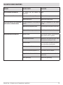
The following table describes the possible alarms indicated by the stove, associated to the respective code that appears on the emergency
panel and helpful tips to solve the problem.
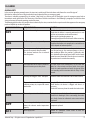
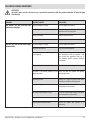
MESSAGE ON DISPLAY TYPE OF PROBLEM SOLUTION
A01
The ame does not light Check the level of pellets in the tank.
Check that the brazier is correctly positioned in its seat
and has no incrustation or unburned material.
Make sure the ignition plug warms up.
Thoroughly empty and clean the brazier before restarting.
A02
The ame is goes out unexpectedly Check the level of pellets in the tank.
Check that the brazier rests correctly in its seat and has no
visible deposits of unburned pellets.
A03
The temperature of the pellet hopper
exceeds the required safety threshold.
The structure overheats due to reduced
heat dissipation.
The structure is too hot because the product has been
used for too long at the maximum power or there is
poor ventilation. When the product is suciently cold,
press button B on the control panel or OFF on the remote
control to cancel alarm A03. Once the alarm is cancelled,
the product can be switched on normally.
A04
The temperature of the exhaust smoke has
exceeded certain preset safety limits.
The stove switches o automatically. Let the stove cool
down for a few minutes and then switch it on again.
Check the smoke expulsion and verify the type of pellet
used according to the instructions found in Chap. 2 of this
manual.
A05
Chimney ue clogged - wind - door open. Check the smoke duct and make sure the door is closed.
The smoke extractor fails to guarantee
sucient primary air, required for correct
combustion.
Draught diculties or brazier clogged.
Check whether the brazier is clogged and clean it, if
necessary.
Check and if necessary clean the smoke duct and air inlet.
A08
Abnormal operation of smoke fan Check cleanliness of the fumes fan compartment and
check if dirt is blocking it. If this is not enough, the smoke
fan is faulty. Contact an authorised service centre to have
it replaced.
A09
The smoke probe is faulty and does not
detect the exhaust smoke temperature
properly.
Contact an authorised service centre to have the
component replaced.
A11
Pellet supply fault Contact an authorised service centre to have the
component replaced.

18
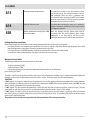
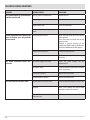
15-ALARMS
A13
Electronic control unit overheating The structure is too hot because the product has been
used for too long at the maximum power or there is
poor ventilation. When the stove is suciently cold,
press button B on the control panel or OFF on the remote
control to cancel alarm A13. Once the alarm is cancelled,
the product can be switched on normally.
A14
Faulty air ow rate sensor This alarm does not block the stove, just a warning is
displayed. Contact an authorised service centre to have
the component replaced.
SER
Routine maintenance warning after 2000
hours of operation
When this ashing message appears upon start-up
it indicates that the preset operating hours before
maintenance is due have elapsed and that an MCZ
qualied technician must be contacted for maintenance.
Exiting the alarm conditions
Follow the procedure described below to restore normal stove operation after an alarm has been triggered:
• Put selector D on the rear emergency panel on OFF for a few seconds, until the 3 digit alarm identity code disappears. The red LED
stops ashing and the sound signal is silenced by performing the steps below.
• Put selector D back in the REMOTE position, to control the operation of the stove via the remote control.
• Switch o the remote control and switch it on again if one wants to restart the stove.
Mechanical stove block
The following conditions may cause the mechanical stove block:
• Structure overheating (“A03”)
• Smoke overheating (“A04”)
• During stove operation air has entered the combustion chamber or there is an obstruction
in the chimney ue (“A05”)
The block is signalled on the display and with a sound signal. In this situation the shutdown stage is activated automatically.When this
procedure is started, any test operation to restore the system is useless. The display signals the cause of the blockage.
SOLUTIONS:
If “A03” appears: the structure is too hot because the product has been used for too long at the maximum power or there is poor ventilation.
When the product is suciently cold, press button B on the control panel or OFF on the remote control to cancel alarm A03. Once the
alarm is cancelled, the product can be switched on normally.
If “A04” appears: The stove switches o automatically. Let the stove cool down for a few minutes and then switch it on again. Check the
smoke expulsion and verify the type of pellet used according to the instructions found in Chap. 2 of this manual.
If “A05” appears: the door has been left open for too long or a signicant amount of air has entered (e.g. missing smoke fan inspection
cap). If these causes are excluded, check and if necessary clean the smoke duct and ue. (it is recommended that this operation is carried
out by an MCZ qualied technician.
The product can be switched on again only after having eliminated the cause permanently.

19
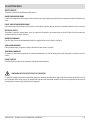
16-RECOMMENDATIONS FOR SAFE USE
Technical Dept. - All rights reserved - Reproduction is prohibited
ONLY CORRECT INSTALLATION AND APPROPRIATE MAINTENANCE AND CLEANING OF THE APPLIANCE CAN GUARANTEE
CORRECT OPERATION AND SAFE USE OF THE PRODUCT.
We would like to inform you that we are aware of cases of malfunctioning of domestic pellet-fuelled heating products, mainly due to
incorrect installation and use, as well as inadequate maintenance.
We would like to assure you that all of our products are extremely safe and certied according to European standards of reference. The
ignition system has been tested with the utmost attention to enhance ignition eciency and to prevent any type of problem, even in the
worst operating conditions. In any case, like for any other pellet-fuelled product, our appliances must be installed correctly and undergo
regular periodical cleaning and maintenance to guarantee safe operation. Our studies show us that malfunctioning is mainly due to the
combination of part or all of the following factors:
• Brazier holes obstructed or brazier deformed, due to lack of maintenance and conditions which can cause delayed ignitions,
generating an anomalous production of unburned gases.
• Insucient combustion air due to a reduced or clogged air inlet duct.
• Use of smoke ducts nonconforming to regulatory installation requirements, failing to guarantee an adequate draught.
• Partially clogged chimney, due to lack of maintenance, reducing the draught and making ignition dicult.
• End chimneypot nonconforming to the indications of the instruction manual, and therefore not suitable to prevent potential inverse
draught.
• This factor is crucial when the product is installed in especially windy areas, such as costal regions.
The combination of one or more of these factors could generate important malfunctioning conditions.
To keep this from occurring, it is fundamental to guarantee that the product is installed in compliance with standards in force.
Furthermore it is of the utmost importance to respect the following simple rules:
• Every time the brazier is removed for cleaning, it must always be put back properly in the work position before using the product,
completely removing any residual lth left on the support base.
• Pellets must never be loaded in the brazier manually, either before ignition or during operation.
• The accumulation of unburned pellets ensuing a failed ignition must be removed before repeating ignition. Also check that they are
fed correctly and that the combustion air inlet/smoke outlet are regular.
• If ignition fails repeatedly, immediately suspend use of the product and contact a qualied technician to check its operation.
Compliance with these indications is absolutely sucient to guarantee proper operation and to avoid any type of problems with the
product.
If the above-mentioned precautions are not taken, and during ignition the brazier is overloaded with pellets thus generating anomalous
smoke in the combustion chamber, carefully follow the indications below:
• Do not disconnect electrical power to the product for any reason whatsoever: this would stop the smoke extractor, releasing smoke
into the environment.
• Take the precaution of opening the windows to ventilate the installation room from any smoke in the environment (the chimney
might not work properly).
• Do not open the re door: this would compromise regular operation of the smoke extraction system to the chimney.
• Just switch the stove o by acting on the on-o button on the control panel (not the rear power supply socket button!) and move
away until smoke has completely evacuated.
• Before attempting re-ignition, clean the brazier and its air passage holes completely of all deposits and unburned pellets. Put
the brazier back in place, removing any residue from its support base. If ignition fails repeatedly, immediately suspend use of the
product and contact a qualied technician to check its operation and the chimney.

T
U
20
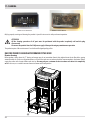
17-CLEANING
Only by properly servicing and cleaning the product is it possible to ensure its safety and correct operation.
ATTENTION!
All the cleaning operations of all parts must be performed with the product completely cold and the plug
disconnected.
Disconnect the product from the 230V power supply before performing any maintenance operation.
The product requires little maintenance if used with certied good quality pellets.
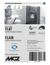
DAILY OR WEEKLY CLEANING PERFORMED BY THE USER
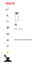
Brazier cleaning
Before ignition, always clean the “T” brazier and remove any ash or incrustation from it that might obstruct the air ow holes, paying
attention to hot ash. In the case of ignition failure, or if fuel in the tank runs out, unburned pellets may accumulate in the brazier. Always
empty the residue in the brazier before each start-up. You may only use a vacuum cleaner to remove ash when it is completely
cold. In this case, use a suitable vacuum cleaner to remove small sized particles.
EXAMPLE OF A CLEAN BRAZIER EXAMPLE OF A DIRTY BRAZIER
Page is loading ...
Page is loading ...
Page is loading ...
Page is loading ...
Page is loading ...
Page is loading ...
Page is loading ...
Page is loading ...
Page is loading ...
Page is loading ...
Page is loading ...
Page is loading ...
-
 1
1
-
 2
2
-
 3
3
-
 4
4
-
 5
5
-
 6
6
-
 7
7
-
 8
8
-
 9
9
-
 10
10
-
 11
11
-
 12
12
-
 13
13
-
 14
14
-
 15
15
-
 16
16
-
 17
17
-
 18
18
-
 19
19
-
 20
20
-
 21
21
-
 22
22
-
 23
23
-
 24
24
-
 25
25
-
 26
26
-
 27
27
-
 28
28
-
 29
29
-
 30
30
-
 31
31
-
 32
32


MCZ MUSA 2.0 Operating instructions
- Category
- Pellet stove
- Type
- Operating instructions
Ask a question and I''ll find the answer in the document
Finding information in a document is now easier with AI
Related papers
-
 MCZ EGO 2.0 AIR OYSTER Installation guide
-
 MCZ MUSA 2.0 Installation guide
-
MCZ EGO–STAR AIR Installation guide
-
 MCZ EN13229 Installation guide
-
 MCZ Flat Use And Installation Manual
-
 MCZ PHILO COMFORT-AIR Use And Installation Manual
-
 MCZ Tube Installation guide
-
 MCZ BOXTHERM 70 PELLET Use And Installation Manual
-
 MCZ VIVO 80 PELLET Use And Installation Manual
-
 MCZ TOBA HYDRO 22 Installation guide


Other documents
-
 Unical PUNTO IT X User manual
-
Extraflame Diadema ACS Idro Owner's manual
-
Extraflame Liliana Idro Owner's manual
-
-
AGA Fusion Pellet Stove Manual Owner's manual
-
Extraflame Divina Plus User manual
-
 Olimpia Splendid MIA 2-11 User manual
-
EGO 10kW M3 Installation guide
-
 TeKKiWear F1 User manual
-
 Olimpia Splendid MIA 2 7.5 User manual


