Page is loading ...

.it
USER OPERATING INSTRUCTIONS
16,5 - 16,5 C


3
Dear Customer,
ank you for having chosen one of our products, the result of many years of experience and of an ongoing
quest for higher quality in terms of safety, reliability and performance.
In this manual, you will nd all the information and useful advice to be able to use your product in the utmost
safety and eciency.
We remind you that the appliance must be commissioned by our Author-
ised Service Centre (Law 37/2008) which will check the installation and ll
out the warranty.
!
• Incorrect installation, maintenance that is not performed properly, and improper use of the product relieves
the manufacturer from any possible damage resulting from use of the stove.
• e appliance must not be used as an incinerator nor must fuel other than pellets be used.
• is manual has been draed by the manufacturer and is an integral part of the product. It must remain with
it during its entire lifetime. Should the product be sold or transferred, always make sure that the booklet is
present as the information it contains is addressed to the purchaser and to all those involved in its installa-
tion, use and maintenance.
• Read the instructions and technical information in this manual carefully before proceeding with installation,
use or any intervention on the product.
• Abiding by the indications provided in this manual guarantees your own safety and that of the product, as well
as working economy and a longer operational life.
• e careful designing and risk analysis performed by our company have produced a safe product. Nonethe-
less, before performing any type of operation, it is recommended to scrupulously comply with the instruc-
tions provided in this document and to always have it on hand.
• Pay the utmost attention when handling ceramic parts, where present.
• Check that the oor where the product is installed is perfectly level.
• e wall where the product is placed must not be made of wood or ammable material. e safety distances
must be maintained.
• While operating, some parts of the stove (door, handle, sides) can reach high temperatures. erefore pay
close attention and use the due precautions especially in the presence of children, elderly, disabled and ani-
mals.
• e stove must be installed by authorised personnel (Authorised Service Centre).
• Diagrams and drawings are supplied as examples; in an eort to pursue a policy of constant development and
renewal of the product, the manufacturer may perform the modications considered appropriate without
any prior notice.
• It is recommended to wear gloves when the stove is at its maximum power output to touch the pellet loading
door and the handle to open door.
• Do not install the stove in bedrooms.
Never cover the body of the stove in any way or obstruct the slits at the top
when the appliance is running. All of our stoves have been tested with in-
line ignition.
In case of a re, disconnect electric power, use an approved re extinguisher and, if needed, call the Fire Bri-
gade. en contact the Authorised Service Centre.
!

4
1.0 Standards and declaration of conformity
Our company declares that the stove complies with the following standards for the European Directive CE
marking.
• 89/336/EEC and 2004/108/EC (EMC directive) and subsequent amendments;
• 2006/95/EC (low voltage directive) and subsequent amendments.;
• 2006/42/EC (machinery directive);
• 89/106/EC (construction products);
• For installation in Italy, refer to UNI 10683/98 or subsequent amendments. e installer of the heating system
must issue the declaration of conformity according to L. 37/2008. All local and national laws and European
standards must be met when installing the appliance;
• EN 60335-1; EN 50165; EN 50366; EN 55014-1; EN 61000-3-2; EN 61000-3-3; EN 14785.
1.1 Information regarding safety
Please read this use and maintenance manual carefully before installing and activating the stove!
If you need explanations, contact your dealer or the Authorised Service Centre.
• e pellet stove must only be operated in domestic environments. is stove is controlled by a circuit board
making combustion fully automatic and controlled; the control unit regulates the ignition phase, 5 output
levels and the extinction phase, guaranteeing safe operation of the stove;
• e basket used for combustion allows most of the ashes produced by burnt pellets to drop into the ash pan.
Nonetheless, check the basket daily as not all pellets have high quality standards (use only quality pellets rec-
ommended by the manufacturer);
• e glass is equipped with a special air pass for self-cleaning. However, it is not possible to avoid a light grey
coating on the glass aer a few hours of work. is also depends on the type of pellet used. Some pellets soil
more than others.
1.2 Liability
With the delivery of this manual, we decline any civil or penal liability for accidents resulting from partial or
total failure to comply with the instructions contained herein.
We decline all liability resulting from improper use of the stove, from incorrect use by the user, from unauthor-
ised changes and/or repairs, from the use of non-original spare parts for this model.
e manufacturer declines any direct or indirect civil or penal liability due to:
• Lack of maintenance;
• Failure to comply with the instructions in the manual;
• Use which does not comply with safety directives;
• Installation which does not comply with the standards in force in the country;
• Installation by unqualied and untrained personnel;
• Changes and repairs not authorised by the manufacturer;
• Use of non-original spare parts;
• Events out of the ordinary.
!
• e stove must only be supplied with quality pellets with a 6 mm diameter, the
type recommended by the manufacturer;
• Before connecting the stove electrically, installation of the exhaust pipes with
the ue must be completed;
• e protective grate inside the pellet tank must never be removed;
• e environment where the stove is installed must have sucient air exchange;
• Never open the oven door while it is operating;

5
• When the stove is running, the surfaces, glass, handle and pipes become
very hot: they must only be touched with adequate protection;
• Keep/preserve the pellets in dry and moisture free rooms;
• Keep both the fuel and any ammable material at an adequate safety dis-
tance from the stove.
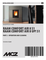
2.0 Function keys and display
Function keys
1. Increase temperature
e button allows you to increase the temperature from a minimum of 7°C to a maximum of 40°C.
2. Decrease temperature
e button allows you to decrease the temperature from a maximum of 40°C to a minimum of 7°C.
3. Setting button
Press the button to access the stove programming menu.
4. ON/OFF
Press the key for 2 seconds: the stove switches on or o.
5. Decrease output
e button allows you to decrease the output from a maximum of 5 to a minimum of 1.
6. Increase output
e button allows you to increase the output from a minimum of 1 to a maximum of 5.
SET
!
2.1 Display indications
7. Chronothermostat LED
Indicates that the weekly and/or daily programming is active.
8. “Smoke discharge” stove functioning LED
is is on when the stove is running.
9-10. Upper/lower display
Dierent stove operating modes are viewed on the display, as well as the temperature and work output set by
the user.
Should the stove malfunction, the display shows the relative error message (see paragraph “Particular cases”).
11. Remote control receiver
Reception sensor of commands given by remote control.
12. “Menu” setting LED
e LED ashes when the desired temperature is set.

6
13. Temperature LED
It switches on when the set temperature is reached. ECO appears on the display.
14. Remote control reception LED
e LED ashes when the remote control is used to change the temperature and/or output.
15. “Pellet” LED
e LED ashes whenever pellets are being loaded into the stove.
Function keys
1. Increase temperature
2. Decrease temperature
3. Menu setting
4. ON/OFF
5. Decrease output
6. Increase output
Display indications
7. Chronothermostat LED
8. Stove operating LED
9. Upper display
10. Lower display
11. Remote control receiver
12. “Menu” setting LED
13. Temperature LED
14. Remote control reception LED
15. Pellet LED
1
2
3
7
8
9
10
11
15
14
13
12
4
5
6
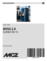
Remote control
1. Increase temperature
2. Decrease temperature
3. Increase output
4. Decrease output
2.2 Description of remote control (optional)
e remote control allows you to control the following
functions:
1. Increase temperature:
Pressing the button increases the temperature
from a minimum of 7°C to a maximum of 40°C.
2. Decrease temperature:
Pressing the button decreases the temperature
from a maximum of 40°C to a minimum of 7°C.
3. Increase output:
Pressing the button increases the output from a
minimum of 1 to a maximum of 5.
+
+
�
�
1
2
3
2
4
Fig. 1
Fig. 2

7
We remind you that the appliance must be commissioned by our qualied
Authorised Service Centre (Law 37/2008), which will check installation and
ll out the warranty.
When commissioning the stove, the room must be well-ventilated as un-
pleasant smells could develop coming from paint and grease in the tube and
shell.
!
4. Decrease output:
Pressing the button
decreases the output from a maximum of 5 to a minimum of 1.
5. Switching stove on and o
Press the keys and simultaneously to switch the stove on or o.
�
+
2.3 Recommendations
• Do not light the stove intermittently: this could cause sparks which shorten the lifetime of the electric com-
ponents;
• Do not touch the stove with wet hands: the electric components of the stove could cause discharges if handled
improperly. Only authorised technicians can deal with possible problems;
• Do not remove any screw from the rebox without rst having lubricated it;
• Never open the door when the pellet stove is operating;
• Make sure that the brazier basket is positioned correctly.
• All sections of the ue gas pipe must be able to be inspected. If xed, it must have inspection openings for
cleaning.
2.4 Loading pellets into tank
Pellets are loaded into the tank through the specic door at the back of the stove.
To load pellets, act as follows:
• Open the door at the top;
• Pour the desired amount of pellets into the tank, with due care (pour enough pellets to guarantee sucient
stove autonomy);
• Close the door.
3.0 Commissioning the stove
3.1 Stove ignition
• Fill the tank up 3/4 with the type of pellets recommended by the manufacturer;
• Connect the stove to a socket using the supplied cable;
• Press the switch at the back of the stove;
• e upper display will read “OFF” and the lower one, the current time;
• Press the key for 2 seconds. Aer a few seconds, the ue gas extractor fan and the ignition resistance
switch on and the text “FAN ACC” appears;
• Aer about 1 minute, the text “LOAD WOOD” appears, the stove loads the pellets and continues lighting the
resistance;
• When the proper temperature is reached, the display will read “FIRE ON”: this means that the stove has
moved to the last ignition phase at the end of which it will be fully operational;

8
ATTENTION!
Before ignition, a bit of smoke could ll the combustion chamber.
!
3.2 Stove extinction
To switch o the stove, press the key until the display reads “OFF”. Even aer extinction of the stove, the
ue gas extractor fan will continue running for a preset amount of time to guarantee quick exhaust of the ue
gas from the combustion chamber.
4.1 Programming stove - chronothermostat (optional)
is function allows you to program two ignitions and two extinctions of the stove during the day or to pro-
gram it weekly.
To enter programming:
• Press the key
SET
twice;
• Select the submenus (UT) using the keys
and .
UT01: Setting current day and switching chronothermostat o.
If the parameter UT01 is set with the current day, for example Sunday (Day 7), select the day of the week to
which to associate PROGRAM 1 and/or PROGRAM 2 ignition.
Change output
It can be changed while the stove is working from a minimum of 1 and a maximum of 5. Press the button
to increase the value and the button to decrease it. e display indicates the output value.
Change temperature
e user can change the temperature at any time. To change the temperature, rst press
SET
and then press
or and select the desired value, which will appear on the lower display.
• Aer a few minutes, the upper display will read “ON 1-2-3-4-5” according to the output set, while the lower
display will show the room temperature;
• When the set temperature is reached, the upper display will read: “ECO” while the detected room temperature
will appear on the lower display;
• e temperature LED switches on when the set temperature is reached;
• Before lighting the stove, make sure that the brazier is clear of pellets and clean from residues of previous
combustion. Otherwise empty and clean it;
ATTENTION:
the brazier must be cleaned daily and the ash pan periodically. Reduced
or lack of cleaning can cause the stove to fail to ignite, damaging the stove
and the environment (possible emissions of non-combusted material and
soot).
Do not put pellets back into the brazier when they did not light.
!
4.0 Adjusting the stove

9
4.2 Programming the stove
Pressing the keys and allows you to select the desired value.
ATTENTION!
Switching on the chronothermostat while the stove is running stops the
digital clock inside the stove during the whole time operations in the
menu are carried out. It is recommended to act on the chronothermostat
menu while the stove is in standby (OFF).
!
UT02: Setting time.
Pressing the key again displays the text UT02 and the lower display views the current hour with ashing
dots. Adjust the hour by acting on the keys and .
UT03: Pressing the key again displays the text UT03 and the lower display views the minutes with ash-
ing dots. Adjust the minutes by acting on the keys and .
UT04: Reserved for Authorised Service Centre.
Pressing the key
SET
again displays the text UT04 reserved for the technician.
Do not modify the set parameters. Modications aer an improper access require the intervention of an au-
thorised technician NOT COVERED BY WARRANTY.
UT05: Indicates the time PROGRAM “1” starts. e time can be changed at 10 minute intervals by acting on
the keys and .
N.B.: is parameter is only enabled if UT01 was previously set other than “OFF”.
UT06: Indicates the time PROGRAM “1” nishes. e time can be changed at 10 minute intervals by acting on
the keys and .
N.B.: is parameter is only enabled if UT01 was previously set other than “OFF”.
UT07:
Allows you to select the day of the week to which to combine PROGRAM “1”.
Press the button to select the day of the week. Press the button to activate/deactivate stove igni-
tion. In the example, the stove is lit on Saturday and Sunday.
SET
SET
Text Meaning
Day 1 Monday
Day 2
Tuesday
Day 3 Wednesday
Day 4 ursday
Day 5 Friday
Day 6 Saturday
Day 7 Sunday
OFF Chronothermostat o
Day 1 Day 2 Day 3 Day 4 Day 5 Day 6 Day 7
Monday Tuesday Wednesday ursday Friday Saturday Sunday
O 1 O 2 O 3 O 4 O 5 On On

10
EXAMPLE
Today is Monday. I want to switch the stove on automatically Monday, Tuesday, ursday and Sunday at 8:00
in the morning and switch it o at 16:00. Wednesday, Friday and Saturday I want to switch it on at 9:00 and
switch it o at 23:00.
ATTENTION!
When programs 1 and 2 have been set, the Timer LED is on. e Timer
LED remains o if programs 1 and 2 have not been set. If electric power
fails, a buer battery switches on, leaving the programmed time settings
unchanged.
!
e program will be as follows:
UT 01: day 1
UT 02: current hour
UT 03: current minutes
UT 04: reserved for technicians and installers
UT 05: 8:00
UT 06: 16:00
UT 07: On1-On2-O3-On4-O5-O6-On7
UT 08: 9:00
UT 09: 23:00
UT 10: O1-O2-0n3-O4-On5-On6-O 7
ATTENTION!
e temperature and output at which the stove operates during the time
periods with programming ON will be those of the last extinction.
!
5.0 Information on display
“OFF”
“OFF” the stove is o or in the extinction phase. E.g: current time 14:30.
UT08:
Indicates the time PROGRAM “2” starts. e time can be changed at 10 minute intervals by acting on the
keys and .
N.B.: is parameter is only enabled if UT01 was previously set other than “OFF”.
UT09: Indicates the time PROGRAM “2” nishes. e time can be changed at 10 minute intervals by acting on
the keys and .
N.B.: is parameter is only enabled if UT01 was previously set other than “OFF”.
UT10: Allows you to select the day of the week to which to combine PROGRAM “2”.
Press the button to select the day of the week. Press the button to activate/deactivate stove igni-
tion.

11
“FIRE ON”
e stove is in the ame stabilisation phase (ame present).
“ON 1”
e stove is in the work phase at the minimum output. e detected room temperature is
29°C.
“ECO”
e stove has reached the temperature set by the user and is in the economy phase. e
output cannot be changed in this phase.
If the temperature is set at 41°C, the stove keeps operating at the set work output without
switching to economy mode (ECO).
“STOP FIRE”
e stove is in the basket self-cleaning phase; the ue gas extractor fan runs at maximum
speed and pellet loading is at minimum (parameter not editable).
5.1 Particular cases
e set temperature must be higher than the temperature detected by the room tempera-
ture probe (+/-1°C). Otherwise the text “ON T” will appear. In this case, to switch on the
stove, set the temperature at least 4°C higher than the one shown on the display.
If the display still reads “ON T”, contact the Authorised Service Centre. Pressing the key
restarts the stove with the previously set parameters.
“SERV” ALARM
When the text “serv” appears, it means the stove has reached 900 working hours. Contact
the Authorised Service Centre for maintenance.
“ALARM NO ACC”: failed ignition
is is triggered when aer the ignition period of approximately 15 min. the ue gas
temperature is still insucient. It can also occur when there is a low amount of pellets at
ignition.
“DEP FAIL”: obstruction in ue gas exhaust pipes
Make sure the ue has no obstructions or excessive lth.
In case of a power failure (even a few seconds), the stove switches o.
e display will read COOL FIRE and the stove will restart aer having performed a cool-
ing cycle.
“FAN - ACC”
e stove is in the resistance preheating phase prior to ignition.
“LOAD WOOD”
Indicates that the stove is in the pellet loading phase.

12
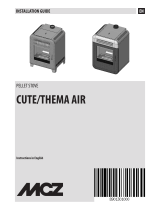
“SIC FAIL”: stove overheating
When the text “SIC FAIL” appears, the pellet gearmotor blocks and the stove enters the
extinction phase.
e stove can be restarted by rearming the thermostat as shown in gure 3.
e manual rearm button is located at the back of the stove (5).
Unscrew the protective cap and press the button below all the way.
In case of further blocks caused by the same problem, do not try to rearm the stove and
contact the Authorised Service Centre.
Fig. 3: manually rearmed
thermostat
1. On-o Switch
2. Power cable
3. Fuse F4AL250V
4. PC connection (optional)
5. ermostat rearm button
6. Room temperature probe
Medium mod.
1 2
3
5
4
6
Large mod.
1
2
4
3
5
6
5
6
3
4
1
2
EXTINCTION ALARM DURING WORK
Triggered when the stove extinguishes during the work phase (e.g.: pellets in tank nished).
e display reads NO FIRE. Press the key to reset the alarm
Empty the brazier and perform another ignition.
FLUE GAS PROBE ALARM
Triggered when the ue gas detection probe fails or is disconnected. e display reads sond
fumi [ ue gas probe], Contact the Authorised Service Centre.
Small mod. 2
6
5
1
2
3
Small mod. 1

13
6.0 Ducting (where present)
e design of this stove follows a specular system with 2 fans situated at the bottom of the stove.
e two fans are completely independent one from another.
A gate valve regulates the air towards the front fan,
towards one rear duct or both rear ducts.
Two knobs at the top of the stove allow you to regu-
late the amount of air to be channelled towards the
right or le rear duct.

14
7.0 Cleaning and maintenance
Before performing any maintenance operation on the stove, take the following precautionary measures:
• Make sure that all parts of the stove are cooled o ;
• Make sure that cinders are completely out;
• Make sure that the main switch is at OFF;
• Unplug the stove thus avoiding accidental contacts;
• When maintenance is over, check that everything is in order like before the intervention (placing the brazier
properly).
Please follow the following cleaning operations carefully. Failure to per-
form them can cause problems to arise in stove operation.
!
Operating options:
1st option: 100% frontal heat
2nd option 60% frontal heat, 40% right or le duct
3rd option: 20% frontal heat, 80% right or le duct
e power of each of the 2 fans together with each of the two ducts can e ectively transmit hot air into other
environments up to a maximum of 8 actual meters away (4 meters for each duct) with an outlet temperature
up to 85° C.

15
7.2 Cleaning metal parts
To clean the metal parts of the stove, use a so cloth moistened in water.
Never clean metal parts with alcohol, thinners, petrol, acetone or other degreasers. Our company will not be
held liable if these substances are used.
Any change in the shade of metal parts can be attributed to inappropriate use of the stove.
Fig. 4: cleaning the brazier
7.3 Cleaning brazier and brazier support
When the ame is red or weak, accompanied by black smoke,
it means that there are ash deposits or incrustations which
hinder the stove from working properly and must be re-
moved (Fig. 4.) Remove the brazier daily by simply liing it
from its seat. en clean any ashes or incrustations that could
have formed, paying close attention to clear the plugged holes
using a pointed tool (not supplied with the stove). is opera-
tion is especially necessary the rst times the stove is lit, espe-
cially if pellets other than those recommended by the manu-
facturer are used. e frequency of this operation depends on
how oen the stove is used and on the choice of pellets.
e brazier support should also be checked, cleaning any ash-
es with a vacuum cleaner.
7.1 Cleaning the surfaces
To clean the surfaces, use a rag soaked with water or, at most, with water and neutral soap.
Using aggressive detergents or thinners can damage the stove surfaces. Before
using any type of detergent, we recommend testing it on a spot out of sight or
contacting the Authorised Service Centre for advice.
!
!
ATTENTION:
the brazier must be cleaned daily and the ash pan periodically. Reduced
or lack of cleaning can cause the stove to fail to ignite damaging the stove
and the environment (possible emissions of non-combusted material and
soot).
Do not put pellets back into the brazier when they did not light.

16
7.7 Ash pan
Open the door and remove the ash pan. Use a vacuum
cleaner to remove all the ashes deposited inside.
is operation may be carried out more or less frequently
depending on the quality of the pellets used (Fig. 9.)
Fig. 9: cleaning the ash pan
7.8 Cleaning the glass
e glass is self-cleaning, meaning that while the stove is operating, a thin layer of air runs along its surface
keeping ashes and lth away; nonetheless within a few hours, a grey coating will form which must be cleaned
as soon as the stove switches o. Soiling of the glass also depends on the quality and quantity of pellets used.
e glass must be cleaned with the stove cooled o with products recommended and tested by our company.
When performing this operation, always look to see whether the grey gasket around the glass is in good con-
dition; failing to check the eciency of this gasket could endanger stove operation. Poor quality pellets can,
however, dirty the glass.
ATTENTION!
Do not try to light the stove if the glass is broken.
!
7.9 Cleaning the exhaust system
Until you have acquired reasonable experience regarding operating conditions, it is recommended to perform
this maintenance operation at least every month.
• Disconnect the power cable;
• Remove the cap of the tee tting and clean the pipes; if necessary, at least the rst couple of times, rely on
qualied personnel;
• oroughly clean the ue gas exhaust system: contact a professional chimney cleaner for this;
• Clean the area behind the inner lining panels from dust, cobwebs, etc. at least once a year, especially the fans.
7.10 Cleaning the fans
e stove is equipped with fans (room and ue gas) located at the back and bottom of the stove.
Any dust or ash deposits on the blades can unbalance it, causing noise while operating.
erefore, the fans must be cleaned at least once a year. Since this operation entails removing some parts of the
stove, the fans should only be cleaned by our Authorised Service Centre.

17
7.11 End of season cleaning
At the end of the season when the stove is no longer used, a more thorough and general cleaning is recommended:
• Remove all the pellets from the tank and from the screw;
• oroughly clean the brazier, the brazier support, the combustion chamber and the ash pan.
If the previous points have been observed, the stove will only require a check. e exhaust pipe or the ue must be
cleaned more thoroughly and the conditions of the basket checked: if needed, order it from the Authorised Service
Centre. If necessary, lubricate the hinges of the door and of the handle. Also check the ceramic bre cord near the
glass on the inner part of the door: if worn or excessively dry, order it from the Authorised Service Centre.
8.0 Replacing parts
8.1 Replacing the glass
e stove is equipped with a 4 mm thick ceramic glass, resistant to a thermal shock of 750°C; it can only be
broken by a strong blow or improper use.
Do not slam the door and do not hit the glass.
Should the glass break, only replace it with an original spare part supplied by the Authorised Service Centre.
Fig. 10: replacing remote control batteries
8.2 Changing remote control battery
When changing the batteries (not supplied), remove the
rear cover of the remote control, making leverage with a
small at head screwdriver (Fig. 10).
Replace the battery with a new “N” type (12V) battery, be-
ing careful not to swap the poles (battery type and poles are
however written on the plastic part of the remote control).
If the problem persists, contact the Authorised Service
Centre.
9.0 Yearly maintenance by Service Centre
ese operations must be programmed yearly by the Authorised Service Centre and are necessary to keep the
product in proper working order guaranteeing its safety.
• orough cleaning of combustion chamber;
• Cleaning and inspection of ue gas exhaust pipe;
• Checking sealing of gaskets;
• Cleaning mechanisms and moving parts (motors and fans);
• Checking electric part and electronic components.
!
Cleaning aer 900 hours or yearly
It is mandatory to clean the stove completely whenever 900 hours of operation are reached
(or at least once a year).
To check the working hours on the display, proceed as follows:
- press the SET key 5 times in a row until you reach parameter UT04, use the temperature
increase/decrease keys to scroll to 01 and conrm once again by pressing the SET key. e
text “Par” appears on the upper display and the actual working hours on the lower one.
- e working hours menu is exited automatically when the menu remains untouched for a
few seconds.

18
9.1 Operations to be carried out every season before ignition.
• General internal and external cleaning;
• orough cleaning of exchange pipes;
• orough cleaning and descaling of brazier and relative compartment;
• Cleaning of motors, mechanical check of backlash and xings;
• Cleaning ue gas duct (replacing gaskets on pipes) and ue gas extraction fan compartment;
• Cleaning silicon tube connected to pressure switch;
• Cleaning, inspection and descaling of ignition resistance compartment, replacement if necessary;
• Cleaning/control of synoptic panel;
• Visual inspection of electric cables, connections and power cable;
• Cleaning pellet tank and checking screw-gearmotor assembly backlash
• Replacing combustion door gasket;
• Functional inspection, screw feeding, ignition, operation for 10 minutes and extinction.
NOTES


00335020 - 1
st
edition 01/14
Unical will not be held responsible for possible inaccuracies due to transcription or printing errors.
It reserves the right to modify its products as deemed necessary or useful, without jeopardising their essential features.
46033 casteldario - mantova - Italy - tel. +39 0376 57001 - telefax +39 0376 660556
inf[email protected] - expor[email protected] - www.unical.eu
www.unical.eu
/