Page is loading ...

MANUALE DI INSTALLAZIONE E UTILIZZO IT
TERMOCAMINO A PELLET
VIVO 80 PELLET
MODELLO COMFORT AIR SLIM
MODELLO COMFORT AIR BASIC
USE AND INSTALLATION MANUAL GB
PELLET THERMO FIREPLACE
VIVO 80 PELLET
COMFORT AIR SLIM MODEL
COMFORT AIR BASIC MODEL
Translation of the original instructions

II
TABLE OF CONTENTS
INTRODUCTION ............................................................................................................1
1 - WARNINGS AND WARRANTY CONDITIONS ....................................................................2
2-INSTALLATION INSTRUCTIONS .....................................................................................5
3-INSTALLATION AND ASSEMBLY ..................................................................................14
4-OPERATION ............................................................................................................. 27
5-LCD REMOTE CONTROL ..............................................................................................29
6-EMERGENCY PANEL .................................................................................................. 34
7-SAFETY DEVICES AND ALARMS ...................................................................................37
8-MAINTENANCE AND CLEANING ..................................................................................41
9-PROBLEMS/CAUSES/SOLUTIONS ................................................................................47
10-WIRING DIAGRAMS ................................................................................................50

1
INTRODUCTION
Technical Dept. - All rights reserved - Reproduction is prohibited
Dear Customer,
Thank you for having chosen our product.
To allow for optimal operation and for you to enjoy the warmth and sense of wellbeing that the re can convey in your
home, we advise you to read this manual carefully before starting up the product for the rst time.
REVISIONS TO THE PUBLICATION
The content of this manual is strictly technical and property of MCZ Group Spa.
No part of this manual can be translated into another language and/or altered and/or reproduced, even partially, in another form, by
mechanical or electronic means, photocopied, recorded or similar, without prior written approval from MCZ Group Spa.
The company reserves the right to make changes to the product at any time without prior notice. The proprietary company reserves its
rights according to the law.
CARE OF THE MANUAL AND HOW TO CONSULT IT
• Take care of this manual and keep it in an easily accessible place.
• Should the manual be misplaced or ruined, request a copy from your retailer or directly from the authorised Technical Assistance
Department.
• “Bold text” requires particular attention.
• “Text in “italics” is used to draw your attention to other paragraphs in this manual or any additional explanation.
• “NOTE” provides the reader with additional information.
SYMBOLS USED IN THE MANUAL
ATTENTION:
carefully read and understand the relative message because failure to comply with that which is written can
cause serious damage to the product and put the user’s safety at risk.
INFORMATION:
failure to comply with these provisions will compromise the use of the product.
OPERATING SEQUENCES:
sequence of buttons to be pressed to access the menus or make adjustments.
MANUAL
carefully read this manual or the relative instructions.

2
1 - WARNINGS AND WARRANTY CONDITIONS
SAFETY PRECAUTIONS
• Installation, electrical connection, functional verication and maintenance must only be performed by qualied or
authorised personnel.
• Install the product in accordance with all the local and national laws and Standards applicable in the relative place,
region or country.
• This product is not intended for use by persons (including children) with reduced physical, sensory or mental
capabilities, or lack of experience and knowledge, unless they are supervised or trained on how to use the product by
a person responsible for their safety.
• Only fuel recommended by the company must be used. The product must not be used as an incinerator. It is strictly forbidden to use
liquid fuel.
• The instructions provided in this manual must always be complied with to ensure the product and any electronic appliances
connected to it are used correctly and accidents are prevented.
• The user, or whoever is operating the product, must read and fully understand the contents of this installation guide before
performing any operation. Errors or incorrect settings can cause hazardous conditions and/or poor operation.
• Do not use the product as a ladder or supporting structure.
• Do not place laundry on the product to dry. Any clothes horses or similar objects must be kept at a safe distance from the product.
Fire hazard.
• AllliabilityforimproperuseoftheproductisentirelybornebytheuserandrelievestheManufacturerfromanycivilandcriminalliability.
• Any type of tampering or unauthorised replacement with non-original spare parts could be hazardous for the operator's safety and
relieves the company from any civil and criminal liability.
• Most of the surfaces of the product can get very hot (door, handle, glass, smoke outlet pipes, etc.). Avoid contact with these
parts unless adequate protective clothing is worn or appropriate means are used, such as heat protective gloves or
cold handles.
• It is forbidden to operate the product with the door open or the glass broken.
• The product must be powered by a system that is equipped with an eective earth system.
• Switch the product o in the event of a fault or malfunctioning.
• Accumulated unburned pellets in the burner after each "failed start-up" must be removed before starting up again.
• Do not wash the product with water. Water could penetrate the unit and damage the electrical insulation, thereby causing electric
shocks.
• Do not stand in front of the product for a long time. Do not overheat the room where the product is installed. This could aect your
physical conditions and cause health problems.
• Do not put any fuel other than wood pellets in the hopper.
• Install the product in rooms that are adequately protected against re and equipped with all the utilities such as supplies (air and
electricity) and smoke outlets.
• If a re breaks out inside the chimney, switch the appliance o, disconnect it from the mains and do not open the door. Then contact
the competent authorities.
• The product and the ceramic/serpentine cladding must be stored in a place where there is no humidity and must not be exposed to
the elements.
• It is recommended not to remove the feet that support the product in order to guarantee adequate insulation, especially if the
ooring is made of ammable material.
• If the ignition system is faulty, do not force ignition with ammable materials.
• Special maintenance must only be performed by authorised and qualied personnel.
• Assess the static conditions of the surface on which the weight of the product will rest and provide suitable insulation if it is made of
ammable material (e.g. wood, tted carpet or plastic).

3
1 - WARNINGS AND WARRANTY CONDITIONS
Technical Dept. - All rights reserved - Reproduction is prohibited
INFORMATION:
Please contact the retailer or qualied personnel authorised by the company to resolve a problem.
• only fuel stipulated by the company must be used.
• Check and clean the smoke outlet pipes regularly (connection with the product).
• The product is not a cooking appliance.
• Always keep the cover of the fuel hopper closed.
• Keep this instruction manual in a safe place as it must accompany the product throughout its working life. If it is sold or transferred
to another user, always make sure that the manual accompanies the product.
INTENDED USE
The product only works with wood pellets and must be installed indoors.
WARRANTY CONDITIONS
The company provides a product warranty, excluding the parts subject to normal wear stipulated below, for a period of two years
from the date of purchase, which is proven by a supporting document that contains the name of the seller and the date when the sale took
place. Warranty cover is valid if the completed warranty is returned within 8 days and the product is installed and tested by a qualied
installer, according to the detailed instructions provided in the instruction manual supplied with the product.
The term ‘warranty’ refers to the (free-of-charge) replacement or repairs of parts acknowledged to be faulty due to manufacturing
defects.
RESTRICTIONS
The above-mentioned warranty does not cover parts of electrical and electronic components and fans, which are covered
for two years from when the product is purchased, proof of which is provided as specied above. The warranty does not cover parts
subject to normal wear, such as: gaskets, glass and all parts that can be removed from the rebox.
Replaced parts will be covered by the warranty for the remaining period of the warranty in force as from the date of purchase of the
product.
EXCLUSIONS
Variations in colour of the painted or ceramic/serpentine parts and crazed ceramics do not constitute grounds for a claim as they are
natural characteristics of the material and product use.
The warranty does not cover any part that may be faulty as a result of negligence or careless use, incorrect maintenance or installation that
does not comply with the company's instructions (see the relative chapters in this user manual).
The company declines all liability for any damage which may be caused, directly or indirectly, to persons, animals or objects as
a consequence of non compliance with all the prescriptions specied in the manual, especially warnings regarding installation,
use and maintenance of the appliance.
If the product does not work correctly, contact your local retailer and/or importer.
Damage caused during transport and/or when handled is excluded from the warranty.
The supplied installation guide is the only reference for installation and product use.
The warranty will be rendered null and void in the event of damage caused by tampering, atmospheric agents, natural disasters, electrical
discharges, re, defects in the electrical system, and maintenance not being performed at all or as indicated by the manufacturer.

4
1 - WARNINGS AND WARRANTY CONDITIONS
INTERVENTION REQUEST
The company declines all liability if the product and any other accessory is used incorrectly or altered without
authorisation.
All parts must be replaced with original spare parts.
The request must be sent to the retailer who will forward it to the Technical Assistance Department.
SPARE PARTS
Only original spare parts must be used. The retailer or service centre can provide all the useful information regarding spare parts.
It is recommended not to wait for the parts to be worn before having them replaced. It is important to perform regular maintenance.
PRECAUTIONS FOR CORRECT DISPOSAL OF THE PRODUCT IN ACCORDANCE WITH THE EUROPEAN DIRECTIVE
2002/96/EC AND ITS SUBSEQUENT AMENDMENT 2003/108 EC.
At the end of its working life, the product must not be disposed of as urban waste.
It must be taken to a special dierentiated waste collection centre set up by the local authorities or to a retailer that provides this service.
Disposing of the product separately prevents possible negative consequences for the environment and health deriving from inappropriate
disposal and allows its materials to be recovered in order to obtain signicant savings in energy and resources.
As a reminder of the need to dispose of appliances separately, the product is marked with a crossed-out wheeled dustbin.

5
2-INSTALLATION INSTRUCTIONS
Technical Dept. - All rights reserved - Reproduction is prohibited
The requirements in this chapter refer to the regulations of the Italian installation Standard UNI 10683. In any case, always comply with
the regulations in force in the country of installation
PELLETS
Wood pellets are obtained from compressing sawdust produced during the processing of natural dried wood (without paint). The
compactness of the material is guaranteed by the lignin contained in the wood itself and allows pellets to be produced without glue or
binders.
The market oers dierent types of pellets with characteristics that vary according to the wood mixtures used. The diameter varies
between 6 and 8 mm, with a standard length ranging from 5 to 30 mm. Good quality pellets have a density that varies between 600 and
over 750 kg/m3, with a moisture content that ranges from 5% to 8% of its weight.
Pellets have technical advantages besides being an ecological fuel, as the wood residue is used completely, thereby achieving cleaner
combustion than that of fossil fuels.
Good-quality wood has a caloric value of 4.4 kW/kg (15% moisture, after about 18 months of seasoning), whereas that of pellets is 4.9
kW/kg. To ensure good combustion, the pellets must be stored in a dry place and protected from dirt. Pellets are usually supplied in 15 kg
bags, therefore, storing them is very convenient.
Good quality pellets guarantee good combustion, thereby decreasing harmful emissions into the atmosphere.
The poorer the quality of the fuel, the more often the internal parts of the brazier and combustion chamber must
be cleaned.
DINplus, Ö-Norm M7135 and Pellet gold are examples of the major quality certications of pellets in the European market and
guarantee that the following are complied with:
• caloric value: 4.9 kWh/kg.
• Moisture content: max 10% of the weight.
• Percentage of ash: max 0.5% of the weight.
• Diameter: 5 – 6 mm.
• Length: max 30 mm.
• Content: 100% untreated wood with no added binding agents (max percentage of bark: 5%).
• Packaging: in bags made from environmentally friendly or biologically decomposable material.
The company strongly recommends using certied fuel for its products (DINplus, Ö-Norm M7135 or Pellet Gold).
Poor quality pellets or others that do not comply with that specied previously compromises the operation of your
product and can therefore render the warranty and product liability null and void.
15KgBAGSOFFUEL

6
2-INSTALLATION INSTRUCTIONS
PRECAUTIONS REGARDING INSTALLATION
IMPORTANT!
Product installation and assembly must be carried out by qualied personnel.
The product must be installed in a suitable place for it to be regularly opened and routine maintenance to be performed.
The site must be:
• compliant for proper operation.
• Equipped with an adequate smoke expulsion system.
• Equipped with ventilation intake from outside.
• Equipped with 230V 50 Hz power supply with an EC compliant earth system.
The product must be connected to a chimney or an internal or external vertical duct that complies with current regulations.
The product must be positioned in such a way that the electrical socket is accessible.
IMPORTANT!
The product must be connected to a chimney or a vertical duct that can expel the smoke at the highest point of the
building.
The smoke derives from the combustion of wood essence and if it comes in contact with or close to walls, the latter
can become dirty. Moreover, utmost attention is required as they are almost invisible but very hot and can cause
burns. The holes of the external air inlet and the smoke outlet pipe must be drilled before positioning the product.
THE OPERATING ENVIRONMENT
For correct operation and even distribution of heat, the product must be placed where the air required for combustion can ow.
The volume of the room should be no less than 15 m
3
.
The air must enter through permanent openings in the walls (near the product) that reach outside with a minimum section of 80 cm
2
without the protective grille.
These openings (air inlets) must be made in such a way that it is impossible for them to be obstructed in any way.
Air can also be drawn from adjacent rooms to the one that is to be ventilated, provided they have an external air inlet and are not used
as a bedroom or bathroom or where there is a re hazard, such as: a garage, wood shed or where ammable materials are stored, and
applicable regulations must be strictly complied with.
If the product is placed too close to the wall it could cause overheating and damage the plaster (yellowing, cracking,
etc.).

7
2-INSTALLATION INSTRUCTIONS
Technical Dept. - All rights reserved - Reproduction is prohibited
POSITIONING AND RESTRICTIONS
In the case of simultaneous installation with other heating appliances, provide appropriate air inlets for each one (according to the
instructions of each product).
The product cannot be installed (except for sealed or closed operation appliances with external ducted combustion
air intake):
• in bedrooms or bathrooms;
• in rooms where there are liquid fuel appliances with continuous or intermittent operation that draw the
combustion air from the room they are installed in;
• in rooms where there are B-type gas heating appliances, with or without domestic hot water production and
interconnecting rooms;
• where another heating appliance is installed without an independent air ow.
It is forbidden to place the product in an explosive atmosphere.
MINIMUM DISTANCES
VIVO 80 PELLET Non-ammable walls Flammable walls
Comfort Air Version
A = 20 mm
B = 20 mm
A = 50 mm
B = 50 mm
If particularly delicate objects are present, such as furniture, curtains or sofas the distance of the product must be signicantly increased.
If the oor is made of wood, it is recommended to place a oor protection in accordance with the Standards in force
in the country of installation.
Heat-sensitive or ammable objects cannot be placed near the product. Keep such objects at a minimum distance of
80 cm from the outermost point of the product.

8
2-INSTALLATION INSTRUCTIONS
CONNECTION OF THE SMOKE EXHAUST DUCT
When drilling the hole for the smoke exhaust pipe, the possible presence of ammable materials must be considered. If the hole must be
made through a wooden wall or thermolabile material, the INSTALLER MUST rst use the relative wall tting (minimum diam. 13 cm)
and adequately insulate the pipe of the product that passes through it, using suitable insulating material (1.3 - 5 cm thick with minimum
thermal conductivity 0.07 W/m°K).
The same minimum distance must be applied if the pipe of the product must pass through vertical or horizontal sections near the
thermolabile wall.
It is recommended to use an insulated double-wall pipe in external sections in order to prevent condensation from forming.
The combustion chamber works in negative pressure.
SMOKEEXHAUSTCOUPLING

9
2-INSTALLATION INSTRUCTIONS
Technical Dept. - All rights reserved - Reproduction is prohibited
Always use pipes and ttings with appropriate seals that guarantee tightness.
It must be possible to inspect all sections of the ue duct and they must be removable for periodic internal cleaning (T-tting with
inspection hole).
Position the product considering all the above requirements and instructions.
IMPORTANT!
The following conditions must be complied with when connecting the appliance to the chimney:
• the smoke duct must be at least category T200 (or higher if required by the smoke temperature of the appliance)
and P1-type (airtight).
• All 90° angles (max. 3) in the smoke exhaust duct must be preferably tted with the relative T-ttings with
inspection hole. (See pellet product accessories).
• It is strictly forbidden to t a mesh at the end of the exhaust pipe as it could cause the product to malfunction
(due to clogging).
• It is forbidden to use counter-sloping pipes.
• The horizontal section of the smoke duct must not be longer than 2-3 m.
• It is also recommended not to exceed 6 metres in length with the pipe Ø 80 mm.
• The smoke duct must not cross rooms in which it is forbidden to install combustion appliances.

A
B
C
10
2-INSTALLATION INSTRUCTIONS
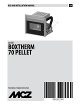
COMBUSTION AIR
During operation a certain amount of air is drawn from the room in which the product is installed and this air must be supplemented
through an air inlet.
The combustion air in this product is autonomously drawn directly from the grille on the pellet loading door. The 65 mm diameter pipe
supplied must be connected to the product and the door as shown in the gure.
The user can decide to draw the combustion air from outside, in which case, the pipe must be connected to the product and an external
air intake.
A-AIRINLETFROMTHEPELLETLOADINGDOOR
B-FLEXIBLEPIPE
C-PIPECONNECTIONTOTHEPRODUCT
HOT AIR OUTLET DUCTING
The product can distribute the hot air by Forced Convection by means of a forced ventilation kit (supplied).
The product comes with two types of kits:
• Comfort Air Slim.
• Comfort Air Basic.
The main characteristics of the two kits are:
• Kit Comfort Air Slim - 12 multi diuser, 60 mm diameter ducting and a motor between the thermo replace and the diuser.
• Kit Comfort Air Basic - 20 multi diuser, 100 mm diameter ducting and a motor behind the fan.
Other optional types of diusers can be applied depending on the kit chosen.
Refer to the relative manual inside the kit for the installation instructions.
An air intake must be installed in the place of installation in order to guarantee the air for combustion.

11
2-INSTALLATION INSTRUCTIONS
Technical Dept. - All rights reserved - Reproduction is prohibited
FANS ELECTRICAL CONNECTION
The kit comes with 2.5 metre long silicone cables for fans cabling. Start cabling as follows:
In position 2 connect the yellow/green wire while in position 1 connect the remaining two wires (the colour sequence does not matter as
the fans do not have polarization) (g.7).
The terminal block, to which one must connect the fan cables (g.8), is screwed to the upper part of the structure .
Connect the two fans earthing cables to the rst clamp on the left (T). Connect the remaining two cables from the LH fan with the clamps
connected to the white cables (B). Connect the remaining two cables from the RH fan with the clamps connected to the purple cables (V).
IMPORTANT!
The fan connection cable is made of silicone to resist high temperatures. In the event of extension cables (over 2.5 m)
and in any case under all circumstances, make sure that the cable does not come into contact with hot parts of the
unit, or with air connecting pipes within the cladding or structure.
FIGURE7–FANSCLAMPSPOSITION FIGURE8–CABLESPOSITIONONTERMINALBLOCK

12
2-INSTALLATION INSTRUCTIONS
CONNECTION TO THE EXTERNAL AIR INLET
It is essential for the room where the product is installed to be adequately ventilated in order to guarantee sucient air for proper
combustion in the appliance. This is possible by means of suitable ventilation openings in the room itself or in an interconnected room
through a permanent opening between the rooms.
For this purpose, drill a hole on the outer wall close to the product with a minimum section of 80 cm² (11 cm in diameter or 10x10 cm if
rectangular, considering the protective grids), protected by a grid on the outside.
The air inlet must also:
• be protected with a grid, metal mesh, etc. without reducing the net section.
• Be positioned in such a way so as not to be obstructed.
• Allow maintenance to be performed.
• Be directly interconnected with the room where the product is installed.
• In the case of ducting, up to 3.5 linear metres, increase the cross-section by about 5%, whereas for longer ducts, increase it by 15%.
Remember that the ventilation grilles always have a useful section in cm
2
on one side. When choosing the grille and
size of the hole, check that the useful section of the grille is larger or equal to the section required by the company
for product operation.
IMPORTANT!
The air ow can also be drawn from an adjacent room to that of the room where the product is installed, provided
the air can ow freely through permanent openings interconnected with the outside; air inlets connected to thermal
units, garages, kitchens or bathrooms must be avoided.
CONNECTION TO THE CHIMNEY
The chimney is the fundamental element for smoke expulsion and must therefore comply with the following requirements:
• be waterproof and thermally insulated.
• Be made of suitable materials that resist mechanical stress over time, heat, the eects of the combustion products and any possible
condensation.
• Have a vertical set-up with deviations from the axis of no more than 45° and free of bottlenecks.
• Must be suitable for the specic operating conditions of the product and have the CE marking (EN1856-1, EN1443).
• Must be adequately sized for the draught/smoke expulsion requirements that are necessary for the product to operate correctly
(EN13384-1).
• The internal section is preferably circular.
• In the case of a pre-existing product that has been used, it must be cleaned.
The chimney is fundamental for correct operation and safety of your product.
Hereunder are a few guidelines for a correct installation. Any alternative congurations must be suitably sized in accordance with the
general method of calculation of UNI EN 13384-1.

0,5 mt.
1
2
3
0,5 mt.
2
1
3
3-5 %
2 - 3 mt. MAX
0
,5 mt.
H
>
1
,5
m
t
.
3
2
1
0,5 mt.
1
2
3
0,5 mt.
2
1
3
3-5 %
2 - 3 mt. MAX
0
,5 mt.
H
>
1
,5
m
t
.
3
2
1
0,5 mt.
1
2
3
0,5 mt.
2
1
3
3-5 %
2 - 3 mt. MAX
0,5 mt.
H
>
1
,
5
m
t
.
3
2
1
13
2-INSTALLATION INSTRUCTIONS
Technical Dept. - All rights reserved - Reproduction is prohibited
CONNECTIONS
CONNECTION TO THE CHIMNEY CONNECTION TO AN EXTERNAL DUCT
WITH AN INSULATED OR DOUBLE-WALL
PIPE
CONNECTION TO THE CHIMNEY
The internal dimensions of the chimney
must not exceed 20x20 cm or 20 cm in
diameter. In the case of larger dimensions
or bad chimney conditions (e.g. cracks,
poor insulation, etc.), it is advisable to t
a stainless steel pipe of suitable diameter
throughout the length of the chimney
right to the top.
The minimum internal dimensions of the
external duct must be 10x10 cm or 10 cm
in diameter and must not exceed 20x20
cm or 20 cm in diameter.
Only stainless steel insulated (double-
wall) pipes must be used, which are
smooth on the inside and xed to the
wall. Flexible stainless steel pipes must
not be used.
The connection between the product and
the chimney or the smoke duct must not
have an inclination that is less than 3% in
the horizontal sections, which must have
a maximum overall length of 2/3 m. The
vertical section between one T-tting and
another (angle) must not be less than
1.5 m.
1)WINDPROOFCHIMNEYPOT 2)CHIMNEY 3)INSPECTIONHOLE
• Use adequate instruments to verify that there is a minimum draught of 5 Pa.
• Set-up an inspection hole at the bottom of the chimney to perform periodic checks and cleaning, which must
be done annually.
• The connection to the chimney must be sealed and the ttings and pipes recommended by us must be used (CE
marked in accordance with EN1856-2 with the minimum requisites: T200 and P1).
• You must ensure that a windproof chimneypot is installed in accordance with the regulations in force.
• This type of connection guarantees smoke expulsion even in the event of a temporary power cut.

A B
1
2 3
4
14
2-INSTALLATION INSTRUCTIONS
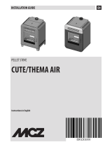
OPERATING PROBLEMS RELATED TO DRAUGHT DEFECTS IN THE CHIMNEY
Among all the weather and geographical conditions that aect chimney operation (rain, fog, snow, altitude a.s.l., exposure to sunlight,
orientation to the cardinal points, etc.), the wind is certainly the most determinant. In fact, besides the thermal depression caused by the
dierence in temperature between inside and outside the chimney, there is another type of depression (or overpressure): dynamic pressure
caused by the wind. An updraft always increases depression and therefore the draught. A horizontal wind increases depression provided the
chimneypot has been installed properly. A downdraft always decreases depression, at times inverting it. Besides the direction and force of the
wind, the position of the chimney and the chimneypot with respect to the roof of the building and the surrounding landscape is also important.
The wind also aects chimney operation indirectly by creating overpressure and depression zones within the building as well as outside.
An internal overpressure can be created in rooms that are directly exposed to the wind (2), which can enhance the draught in stoves and
replaces, however, it can be counteracted by the external overpressure if the chimneypot is situated on the side exposed to the wind
(1). On the other hand, a dynamic depression can be created in rooms that are opposite the wind direction (3), which competes with the
natural thermal depression generated by the chimney, however, this can be compensated for (sometimes) by placing the smoke duct
opposite the wind direction (4).
IMPORTANT!
The operation of the pellet product is signicantly aected by the chimney layout and position.
Hazardous conditions can only be resolved by qualied personnel setting the product appropriately.
A=LESSFAVOURABLEPOINTS
B=THEMOSTFAVOURABLEPOSITION

478
209
265
39
15°
601
540
10
37
710
786.5
706.6
40
40
677
40
40
Ø 100
Ø 100
Ø 65
Ø 100
Ø 100
540
10
Ø 80
Ø 213
15
3-INSTALLATION AND ASSEMBLY
Technical Dept. - All rights reserved - Reproduction is prohibited
DRAWINGS AND CHARACTERISTICS
DIMENSIONS: VIVO 80 PELLET

16
3-INSTALLATION AND ASSEMBLY
TECHNICAL CHARACTERISTICS VIVO 80 PELLET COMFORT AIR (SLIM-BASIC)
Nominal output power 10,5 kW (9030 kcal/h)
Minimum output power 2,7 kW (2322 kcal/h)
Eciency at Max 92,2%
Eciency at Min 95,8%
Temperature of exhaust smoke at Max 170 °C
Temperature of exhaust smoke at Min 70 °C
Particulate/OGC/Nox (13%O
2
) 19 mg/Nm
3
- 2 mg/Nm
3
- 133 mg/Nm
3
CO at 13% O
2
at Min and at Max 0,03 – 0,01%
CO
2
at Min and at Max 6,4% - 8,1%
Recommended draught at Max power 0,10 mbar - 10 Pa
Recommended draught at Min power 0,05 mbar - 5 Pa
Mass of smoke 8,9 g/sec
Hopper capacity 20+15 litres
Type of pellet fuel Pellet diameter 6-8 mm and size 5/30 mm
Pellet hourly consumption Min ~ 0.6 kg/h* - Max ~ 2.2 kg/h*
Autonomy At min ~ 39 h* - At max ~ 11 h*
Heatable volume m
3
226/40 – 258/35 – 301/30 **
Combustion air inlet External diameter 50 mm
Smoke outlet External diameter 80 mm
Air inlet 80 cm
2
Nominal electrical power (EN 60335-1) 100 W (Max 420 W)
Supply voltage and frequency 230 Volt / 50 Hz
Net weight 170 kg
Weight with packaging 190 kg
* These data may vary according to the type of pellets used.
** Heatable volume based on the requested power per m3 (respectively 40-35-30 Kcal/h per m3).
Tested according to EN 14785 in accordance with Directive 89/106/EEC (Construction Products).

A
A
C
B
17
3-INSTALLATION AND ASSEMBLY
Technical Dept. - All rights reserved - Reproduction is prohibited
PREPARATION AND UNPACKING
The product is supplied in a single package. The pipe, feeding door and ventilation grille are packaged inside. A box is placed on top of the
package with the Comfort Air Slim or Basic Kit inside.
Open the package, remove the product from the pallet and set it in the pre-selected place, making sure this complies with the requirements.
The two brackets must be removed in order to remove the product from pallet, by loosening the two anged nuts and the two screws.
The appliance must always remain in a vertical position and handled solely with a cart. Pay particular attention to the door and its glass,
protecting them from mechanical knocks that would compromise their integrity.
In any case, the product must always be handled with care. If possible, unpack the product near the place of installation. The packaging
materials are neither toxic nor harmful, and therefore no particular disposal measures are required. Therefore, the end user is responsible
for product storage, disposal or possible recycling in compliance with the relative applicable laws.
If the product must be connected to an exhaust pipe that goes through the rear wall (to enter the ue), make sure not to force it in.
PACKAGING:VIVO80PELLET
COMFORTAIR
A-SCREW
B-NUT
C-BRACKET

18
3-INSTALLATION AND ASSEMBLY
POSITIONING
Evaluate the optimal condition of installation before placing the product.
The product can be installed in an existing traditional rebox or as a new system.
Furthermore, an iron support can be purchased separately in order to raise the product to the recommended height, 500 mm, (see the
relative price list of accessories - optional) or build a base on site.
INSTALLING IN AN EXISTING FIREBOX
Evaluate the following elements:
The product support surface must have the following characteristics:
• bear the weight of the product and any accessories
• its texture must allow anchors to be set with dowels for safety purposes
• be perfectly level
• the back panels must be as perpendicular to the surface as possible
The housing compartment must not wide enough for the product to t in.
After having veried the conditions required for a correct installation, proceed with the product assembly:
• fasten the base of the product to the support surface
• make the various connections to the replace in compliance with all the applicable regulations.
Any space between the cladding walls and the product can be closed with a compensation frame that must be easily removed if
maintenance is to be performed on the insert.
It is mandatory for the product to be fastened to the support surface as it may tip over when being extracted.
Verify that all the connections (hydraulic and electrical) allow the product to be extracted.
INSTALLING AS A NEW SYSTEM
Evaluate the following elements:
The product support surface must have the following characteristics:
• bear the weight of the product and any accessories
• its texture must allow anchors to be set with dowels for safety purposes
• be perfectly level
After having veried the conditions required for a correct installation, proceed with the product assembly:
• fasten the base of the product to the support surface
• make the various connections to the replace in compliance with all the applicable regulations.
It is mandatory for the product to be fastened to the support surface as it may tip over when being extracted.
Verify that all the connections allow the product to be extracted.
• Proceed with the cladding assembly.
/